Installation Guide
Page 1
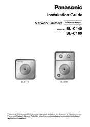
Installation Guide Network Camera Outdoor Ready Model No. Panasonic Network Camera Website: http://panasonic.co.jp/pcc/products/en/netwkcam/ regionlinks/index.html BL-C140 BL-C160 BL-C140 BL-C160 Please read this document before using the product, and save this document for future reference.
Installation Guide Network Camera Outdoor Ready Model No. Panasonic Network Camera Website: http://panasonic.co.jp/pcc/products/en/netwkcam/ regionlinks/index.html BL-C140 BL-C160 BL-C140 BL-C160 Please read this document before using the product, and save this document for future reference.
Installation Guide
Page 2
Available features and operations vary slightly depending on the front of your camera by checking the model no . BL-C140A, BL-C140CE, BL-C140E, BL-C160A, BL-C160CE, BL-C160E Please read the included Important Information before proceeding. Features and operations that it can confirm the model no . ... • UPnP is the abbreviation for "Universal Plug and Play". • The Network Camera is referred to as "the camera" in this document. • The Setup CD-ROM is written for details regarding the camera's features. • Refer to the Troubleshooting Guide on the CD-ROM if you have...
Available features and operations vary slightly depending on the front of your camera by checking the model no . BL-C140A, BL-C140CE, BL-C140E, BL-C160A, BL-C160CE, BL-C160E Please read the included Important Information before proceeding. Features and operations that it can confirm the model no . ... • UPnP is the abbreviation for "Universal Plug and Play". • The Network Camera is referred to as "the camera" in this document. • The Setup CD-ROM is written for details regarding the camera's features. • Refer to the Troubleshooting Guide on the CD-ROM if you have...
Installation Guide
Page 3
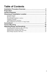
Table of Contents Installation Procedure Overview 4 Preparation 5 Camera Diagrams 7 Choosing an Installation Location 9 Detection Features...9 Mounting Location...13 Recommended Installation Locations 14 Installation Examples ...15 Light Brightness (BL-C160 Only 16 Effect of Brightness and Distance on Image Quality 16 Connections 17 Camera Mounting 18 Adjusting Range and Sensitivity 23 Preventing Sensor Interference (BL-C160 Only 23 Adjusting Motion Detection Sensitivity 25 Adjusting Sensor Sensitivity (BL-C160 Only 26 Sensor Range Caps (BL-C160 Only 27 3
Table of Contents Installation Procedure Overview 4 Preparation 5 Camera Diagrams 7 Choosing an Installation Location 9 Detection Features...9 Mounting Location...13 Recommended Installation Locations 14 Installation Examples ...15 Light Brightness (BL-C160 Only 16 Effect of Brightness and Distance on Image Quality 16 Connections 17 Camera Mounting 18 Adjusting Range and Sensitivity 23 Preventing Sensor Interference (BL-C160 Only 23 Adjusting Motion Detection Sensitivity 25 Adjusting Sensor Sensitivity (BL-C160 Only 26 Sensor Range Caps (BL-C160 Only 27 3
Installation Guide
Page 4
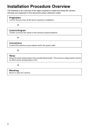
... Procedure Overview The following is an overview of the camera's physical features. Setup Setup the camera (described in this document unless otherwise noted. Connections Connect the camera to your network and to install and setup the camera. This involves configuring the camera so that you know the names of the steps required to the power outlet...
... Procedure Overview The following is an overview of the camera's physical features. Setup Setup the camera (described in this document unless otherwise noted. Connections Connect the camera to your network and to install and setup the camera. This involves configuring the camera so that you know the names of the steps required to the power outlet...
Installation Guide
Page 5
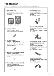
...; Washer L (1 pc. PFJA02A006Z Cord Length: About 1.8 m (5 feet 11 inches) BL-C140CE/BL-C160CE Order No. for wall mounting the camera. PSJA1106Z Cord Length: About 1.8 m (5 feet 11 inches) BL-C140E/BL-C160E 5 PQLV206Y Cord Length: About 3 m (9 feet 10 inches) BL-C140A/BL-C160A BL-C140 BL-C160 … Screw A (6 pcs.) Order No. XWG4F16VW Used when securing the safety wire to the...
...; Washer L (1 pc. PFJA02A006Z Cord Length: About 1.8 m (5 feet 11 inches) BL-C140CE/BL-C160CE Order No. for wall mounting the camera. PSJA1106Z Cord Length: About 1.8 m (5 feet 11 inches) BL-C140E/BL-C160E 5 PQLV206Y Cord Length: About 3 m (9 feet 10 inches) BL-C140A/BL-C160A BL-C140 BL-C160 … Screw A (6 pcs.) Order No. XWG4F16VW Used when securing the safety wire to the...
Installation Guide
Page 6
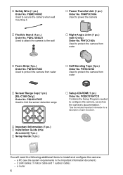
...(see the system requirements in the Important Information document) - 2 LAN cables (1 indoor cable and 1 outdoor cable) - PQME10080Z Used to install and configure the camera. - PNYCC160A Used to protect the camera from water … Foam Strip (1pc.) Order No. PQHG10765Z Used to the wall … Right-Angle...PQHG10748Z Used to protect the camera from water … Self Bonding Tape (1pc.) Order No. PSHG1235Z Used to power the camera … Flexible Stand (1 pc.) Order No. PNWP3C160A Used to protect the camera from water … Sensor Range Cap (1 pc.) [BL-C160 Only] Order No....
...(see the system requirements in the Important Information document) - 2 LAN cables (1 indoor cable and 1 outdoor cable) - PQME10080Z Used to install and configure the camera. - PNYCC160A Used to protect the camera from water … Foam Strip (1pc.) Order No. PQHG10765Z Used to the wall … Right-Angle...PQHG10748Z Used to protect the camera from water … Self Bonding Tape (1pc.) Order No. PSHG1235Z Used to power the camera … Flexible Stand (1 pc.) Order No. PNWP3C160A Used to protect the camera from water … Sensor Range Cap (1 pc.) [BL-C160 Only] Order No....
Installation Guide
Page 7
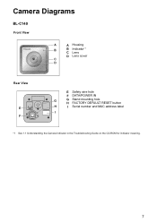
Camera Diagrams BL-C140 Front View A A Housing B B Indicator*1 C Lens D Lens cover C D Rear View E F E Safety wire hole F DATA/POWER IN G G Stand mounting hole H FACTORY DEFAULT RESET button H I Serial number and MAC address label I *1 See 1.1 Understanding the Camera Indicator in the Troubleshooting Guide on the CD-ROM for indicator meaning. 7
Camera Diagrams BL-C140 Front View A A Housing B B Indicator*1 C Lens D Lens cover C D Rear View E F E Safety wire hole F DATA/POWER IN G G Stand mounting hole H FACTORY DEFAULT RESET button H I Serial number and MAC address label I *1 See 1.1 Understanding the Camera Indicator in the Troubleshooting Guide on the CD-ROM for indicator meaning. 7
Installation Guide
Page 8
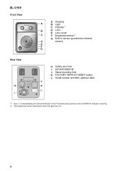
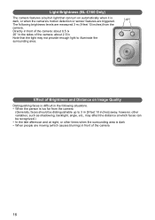
BL-C160 Front View A Housing A B Light C Indicator*1 B D Lens E Lens cover C F Brightness sensor*2 G Built-in sensor (pyroelectric infrared D sensor) E F G Rear View H I H Safety wire hole I DATA/POWER IN J Stand mounting hole K FACTORY DEFAULT RESET button L Serial number and MAC address label J K L *1 See 1.1 Understanding the Camera Indicator in the Troubleshooting Guide on the CD-ROM for indicator meaning. *2 The brightness sensor determines when the light turns on. 8
BL-C160 Front View A Housing A B Light C Indicator*1 B D Lens E Lens cover C F Brightness sensor*2 G Built-in sensor (pyroelectric infrared D sensor) E F G Rear View H I H Safety wire hole I DATA/POWER IN J Stand mounting hole K FACTORY DEFAULT RESET button L Serial number and MAC address label J K L *1 See 1.1 Understanding the Camera Indicator in the Troubleshooting Guide on the CD-ROM for indicator meaning. *2 The brightness sensor determines when the light turns on. 8
Installation Guide
Page 9
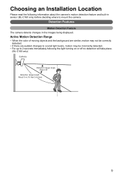
Choosing an Installation Location Please read the following information about the camera's motion detection feature and built-in the images being displayed. Active Motion Detection Range • When the color of moving objects and the background are ...; If there are sudden changes to overall light levels, motion may be incorrectly detected. • For up to mount the camera. Detection Features Motion Detection Feature The camera detects changes in sensor (BL-C160 only) before deciding where to 2 seconds immediately following the light turning on or off no detection will take place...
Choosing an Installation Location Please read the following information about the camera's motion detection feature and built-in the images being displayed. Active Motion Detection Range • When the color of moving objects and the background are ...; If there are sudden changes to overall light levels, motion may be incorrectly detected. • For up to mount the camera. Detection Features Motion Detection Feature The camera detects changes in sensor (BL-C160 only) before deciding where to 2 seconds immediately following the light turning on or off no detection will take place...
Installation Guide
Page 10
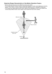
This is done in moving objects. Detection Range Characteristics of the camera. Difficult to detect Easy to changes in brightness. • The camera can easily detect motion when objects move sideways in front of the camera, but cannot easily detect motion when objects move toward the front of the Motion Detection Feature • Motion detection becomes more difficult as it becomes darker. • The motion detection function works by detecting changes in contour and brightness in order to reduce inaccurate detections due to detect Detection range About 58q Camera 10
This is done in moving objects. Detection Range Characteristics of the camera. Difficult to detect Easy to changes in brightness. • The camera can easily detect motion when objects move sideways in front of the camera, but cannot easily detect motion when objects move toward the front of the Motion Detection Feature • Motion detection becomes more difficult as it becomes darker. • The motion detection function works by detecting changes in contour and brightness in order to reduce inaccurate detections due to detect Detection range About 58q Camera 10
Installation Guide
Page 11
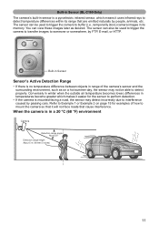
... Detection Range • If there is no temperature difference between objects in its range that cause interference. Built-in Sensor (BL-C160 Only) The camera's built-in temperatures become greater which means it uses infrared rays to detect temperature differences within its memory. You can also be...detect properly. The sensor can view these images later as on page 15 for the sensor to mount the camera so that it easier for examples of the camera's sensor and the surrounding environment, such as desired. Conversely in winter when the outside air temperature becomes lower,...
... Detection Range • If there is no temperature difference between objects in its range that cause interference. Built-in Sensor (BL-C160 Only) The camera's built-in temperatures become greater which means it uses infrared rays to detect temperature differences within its memory. You can also be...detect properly. The sensor can view these images later as on page 15 for the sensor to mount the camera so that it easier for examples of the camera's sensor and the surrounding environment, such as desired. Conversely in winter when the outside air temperature becomes lower,...
Installation Guide
Page 12
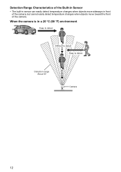
When the camera is in front of the camera, but cannot easily detect temperature changes when objects move toward the front of the Built-in Sensor • The built-in sensor can easily detect temperature changes when objects move sideways in a 20 °C (68 °F) environment Easy to detect Diffictult to detect Easy to detect Detection range About 63q Camera 12 Detection Range Characteristics of the camera.
When the camera is in front of the camera, but cannot easily detect temperature changes when objects move toward the front of the Built-in Sensor • The built-in sensor can easily detect temperature changes when objects move sideways in a 20 °C (68 °F) environment Easy to detect Diffictult to detect Easy to detect Detection range About 63q Camera 12 Detection Range Characteristics of the camera.
Installation Guide
Page 13
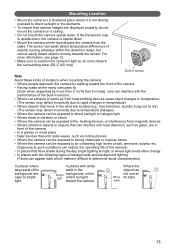
... with heat detection, such as not to disturb the surrounding area. (BL-C160 only) Built-in sensor Note Avoid these kinds of locations when mounting the camera. • Where people approach the camera by walking toward the camera White walls Where the object has the sun at night, or where ...; In places that have shade during the day, bright lighting at its back 13 If the Panasonic logo is upside down, the camera is vibration or shock • Where the camera can be exposed to such conditions can reduce the operating life of objects moving sideways within the detection range,...
... with heat detection, such as not to disturb the surrounding area. (BL-C160 only) Built-in sensor Note Avoid these kinds of locations when mounting the camera. • Where people approach the camera by walking toward the camera White walls Where the object has the sun at night, or where ...; In places that have shade during the day, bright lighting at its back 13 If the Panasonic logo is upside down, the camera is vibration or shock • Where the camera can be exposed to such conditions can reduce the operating life of objects moving sideways within the detection range,...
Installation Guide
Page 14
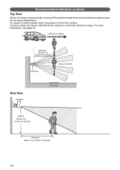
It is easy to detect people coming off the street towards the property and where passing cars do not cause interference. Recommended Installation Locations Top View Where it is easier to detect people when they pass in front of the camera. Difficult to detect Distance About 3 m (9 feet 10 inches) Camera Easy to control the detection range. A sensor range cap can be attached to the camera to detect Side View Camera Entrance Height About 3 m (9 feet 10 inches) Distance About 3 m (9 feet 10 inches) 14 For more information, see page 27.
It is easy to detect people coming off the street towards the property and where passing cars do not cause interference. Recommended Installation Locations Top View Where it is easier to detect people when they pass in front of the camera. Difficult to detect Distance About 3 m (9 feet 10 inches) Camera Easy to control the detection range. A sensor range cap can be attached to the camera to detect Side View Camera Entrance Height About 3 m (9 feet 10 inches) Distance About 3 m (9 feet 10 inches) 14 For more information, see page 27.
Installation Guide
Page 15
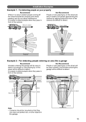
...street are easy to detect, but people or cars passing by walking toward the front of the camera. Difficult to detect Easy to detect Camera Easy to detect Entrance Difficult to detect Camera Entrance Example 2: For detecting people entering an area like a garage Recommend Intruders entering the garage ...will be easy to detect, but people approaching the camera by on your property Recommend Where it is easy to detect people coming off the street towards the property and where passing cars ...
...street are easy to detect, but people or cars passing by walking toward the front of the camera. Difficult to detect Easy to detect Camera Easy to detect Entrance Difficult to detect Camera Entrance Example 2: For detecting people entering an area like a garage Recommend Intruders entering the garage ...will be easy to detect, but people approaching the camera by on your property Recommend Where it is easy to detect people coming off the street towards the property and where passing cars ...
Installation Guide
Page 16
...late afternoon and at which faces can turn on automatically when it is dark • When people are measured 3 m (9 feet 10 inches) from the camera (Generally, faces should be distinguishable up to 3 m [9 feet 10 inches] away, however, other variables, such as shadowing, backlight, angle, etc.,... enough light to illuminate the surrounding area. The following situations. • When the person is too far from the camera. Light Brightness (BL-C160 Only) The camera features a built-in light that the light may affect the distance at night, or other times when the surrounding area...
...late afternoon and at which faces can turn on automatically when it is dark • When people are measured 3 m (9 feet 10 inches) from the camera (Generally, faces should be distinguishable up to 3 m [9 feet 10 inches] away, however, other variables, such as shadowing, backlight, angle, etc.,... enough light to illuminate the surrounding area. The following situations. • When the person is too far from the camera. Light Brightness (BL-C160 Only) The camera features a built-in light that the light may affect the distance at night, or other times when the surrounding area...
Installation Guide
Page 17
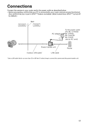
... camera to your router and to the power outlet as described below. • Before proceeding, confirm that your PC is enabled. (Most routers have UPnP™ turned off by default.) Outside Wall Inside AC adaptor To the power outlet (For BL-C140CE/ BL-C140E/ BL-C160CE/ BL-C160E use an AC cord) Power transfer unit Outdoor...
... camera to your router and to the power outlet as described below. • Before proceeding, confirm that your PC is enabled. (Most routers have UPnP™ turned off by default.) Outside Wall Inside AC adaptor To the power outlet (For BL-C140CE/ BL-C140E/ BL-C160CE/ BL-C160E use an AC cord) Power transfer unit Outdoor...
Installation Guide
Page 18
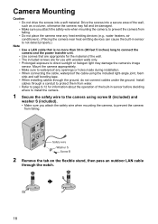
...exposure to direct sunlight or halogen light may damage the camera's image sensor. Safety wire Washer S Screw B 2 Remove the tab on the flexible stand, then pass an outdoor LAN cable through the ground, do not connect cables under the ground. Camera Mounting Caution • Do not drive the screws into ...a secure area of the wall, such as a column, otherwise the camera may fall and be damaged. • Make ...
...exposure to direct sunlight or halogen light may damage the camera's image sensor. Safety wire Washer S Screw B 2 Remove the tab on the flexible stand, then pass an outdoor LAN cable through the ground, do not connect cables under the ground. Camera Mounting Caution • Do not drive the screws into ...a secure area of the wall, such as a column, otherwise the camera may fall and be damaged. • Make ...
Installation Guide
Page 19
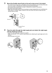
...to place. • Make sure that are suited for the type of the wall to the camera. • Securely fasten all screws. 19 Drive the screws into a secure area of the wall, such as a column...8226; Use screws that the "↑UP" symbol is firmly mounted on the other side of material the camera is mounted to. • Be careful not to nip the cable. • Make sure the flexible... stand is pointing up when attaching the right-angle joint to make sure the camera does not drop. Screw A At least 25 mm (1 inch) 4 Pass the cable through the right-angle joint...
...to place. • Make sure that are suited for the type of the wall to the camera. • Securely fasten all screws. 19 Drive the screws into a secure area of the wall, such as a column...8226; Use screws that the "↑UP" symbol is firmly mounted on the other side of material the camera is mounted to. • Be careful not to nip the cable. • Make sure the flexible... stand is pointing up when attaching the right-angle joint to make sure the camera does not drop. Screw A At least 25 mm (1 inch) 4 Pass the cable through the right-angle joint...
Installation Guide
Page 20
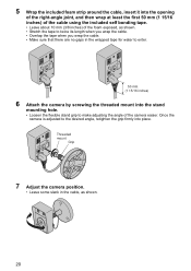
... angle of the foam exposed, as shown. 20 5 Wrap the included foam strip around the cable, insert it into place. Threaded mount Grip 7 Adjust the camera position. • Leave some slack in the cable, as shown. • Stretch the tape to twice its length when you wrap the cable. • Overlap... the cable. • Make sure that there are no gaps in the wrapped tape for water to enter. 50 mm (1 15/16 inches) 6 Attach the camera by screwing the threaded mount into the stand mounting hole. • Loosen the flexible stand grip to the desired angle, retighten the grip firmly into...
... angle of the foam exposed, as shown. 20 5 Wrap the included foam strip around the cable, insert it into place. Threaded mount Grip 7 Adjust the camera position. • Leave some slack in the cable, as shown. • Stretch the tape to twice its length when you wrap the cable. • Overlap... the cable. • Make sure that there are no gaps in the wrapped tape for water to enter. 50 mm (1 15/16 inches) 6 Attach the camera by screwing the threaded mount into the stand mounting hole. • Loosen the flexible stand grip to the desired angle, retighten the grip firmly into...


