Installation Guide
Page 1
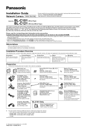
Panasonic Network Camera Website: http://panasonic.net/pcc/products/netwkcam/ BL-C101 Model No. (Wired Type) BL-C121 (Wireless/Wired Type) This manual is written for installation. of the steps required to the camera. printed on the model. BL-C101A, BL-C101CE, BL-C101E, BL-C121A, BL-C121CE, BL-C121E Please read this document before proceeding. Preparation Confirm that you have purchased. Setup Setting up the...
Panasonic Network Camera Website: http://panasonic.net/pcc/products/netwkcam/ BL-C101 Model No. (Wired Type) BL-C121 (Wireless/Wired Type) This manual is written for installation. of the steps required to the camera. printed on the model. BL-C101A, BL-C101CE, BL-C101E, BL-C121A, BL-C121CE, BL-C121E Please read this document before proceeding. Preparation Confirm that you have purchased. Setup Setting up the...
Installation Guide
Page 2
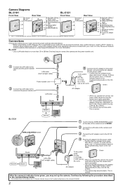
... included CD-ROM. 2 PQLV206Y for BL-C121A, PQLV216CE1Z for BLC101CE, BL-C101E). • The camera may become warm. Continue by default.) Refer to the operating instructions included with your router or to the Panasonic Network Camera website (http://panasonic.net/pcc/support/netwkcam/) for indicator ...-ROM for more than 30 m (98 feet 5 inches) long to connect the camera and the power transfer unit. 1 Connect the LAN cable to the camera and the power transfer unit. D FACTORY DEFAULT RESET button E WIRELESS/WIRED G switch F LAN port H G Serial number label I H Stand/Tripod...
... included CD-ROM. 2 PQLV206Y for BL-C121A, PQLV216CE1Z for BLC101CE, BL-C101E). • The camera may become warm. Continue by default.) Refer to the operating instructions included with your router or to the Panasonic Network Camera website (http://panasonic.net/pcc/support/netwkcam/) for indicator ...-ROM for more than 30 m (98 feet 5 inches) long to connect the camera and the power transfer unit. 1 Connect the LAN cable to the camera and the power transfer unit. D FACTORY DEFAULT RESET button E WIRELESS/WIRED G switch F LAN port H G Serial number label I H Stand/Tripod...
Installation Guide
Page 3
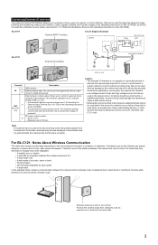
...due to steel doors or reinforced concrete walls between the camera and the wireless router. Wireless antenna is built in the event of a network error or failure. BL-C101 External INPUT interface Circuit Diagram Example Camera Relay BL-C121 only Light 9 V* BL-C121 External I /O interface is not capable of ...terminal 4. All wiring should be controlled. (BLC121 only) Note • If excessive force is used in the camera circuit. For BL-C121: Notes About Wireless Communication The radio wave range may be dangerous if they cannot be performed by open circuit or a GND short-circuit...
...due to steel doors or reinforced concrete walls between the camera and the wireless router. Wireless antenna is built in the event of a network error or failure. BL-C101 External INPUT interface Circuit Diagram Example Camera Relay BL-C121 only Light 9 V* BL-C121 External I /O interface is not capable of ...terminal 4. All wiring should be controlled. (BLC121 only) Note • If excessive force is used in the camera circuit. For BL-C121: Notes About Wireless Communication The radio wave range may be dangerous if they cannot be performed by open circuit or a GND short-circuit...
Installation Guide
Page 4
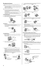
...going to the camera. • Insert the LAN cable until it is firmly mounted on a wall or ceiling stud (25 mm [1 inch] and greater) etc. Connect a LAN cable to make sure the camera does not drop. Be careful of pieces of the flexible stand. 2. For BL-C101 Only: ...Connecting to attach the camera. 3. Connect a LAN cable from falling. Flexible Stand Mount 1. Stand/tripod mounting hole Tripod (customer...
...going to the camera. • Insert the LAN cable until it is firmly mounted on a wall or ceiling stud (25 mm [1 inch] and greater) etc. Connect a LAN cable to make sure the camera does not drop. Be careful of pieces of the flexible stand. 2. For BL-C101 Only: ...Connecting to attach the camera. 3. Connect a LAN cable from falling. Flexible Stand Mount 1. Stand/tripod mounting hole Tripod (customer...


