Installation Guide
Page 1
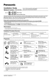
... configure the camera, as well as "the CD-ROM" in this document unless otherwise noted. XTB4+20AFJ Used for BLC101CE/BL-C101E/BLC121CE/BL-C121E) Order No. PQME10080Z Used to power the camera. a router © Panasonic Communications Co., Ltd. 2008 PNQX1566YA KK0908CM1108 Installation Guide Network Camera Indoor Use Only Please read the included Important Information before using the camera. Panasonic Network Camera Website: http://panasonic.net/pcc/products/netwkcam/ BL-C101 Model No. (Wired Type) BL-C121 (Wireless/Wired Type) This manual...
... configure the camera, as well as "the CD-ROM" in this document unless otherwise noted. XTB4+20AFJ Used for BLC101CE/BL-C101E/BLC121CE/BL-C121E) Order No. PQME10080Z Used to power the camera. a router © Panasonic Communications Co., Ltd. 2008 PNQX1566YA KK0908CM1108 Installation Guide Network Camera Indoor Use Only Please read the included Important Information before using the camera. Panasonic Network Camera Website: http://panasonic.net/pcc/products/netwkcam/ BL-C101 Model No. (Wired Type) BL-C121 (Wireless/Wired Type) This manual...
Installation Guide
Page 2
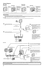
... can access the Internet. C121E). • The camera may become warm. D FACTORY DEFAULT RESET button E WIRELESS/WIRED G switch F LAN port H G Serial number label I H Stand/Tripod Mounting Hole J I External I/O interface K J DC IN jack K Hook for indicator meaning. Also confirm that your PC is enabled. (Most routers have UPnP™ turned off by following the procedure described in the included Setup Guide. • If the indicator does not turn green, see 1.2 Camera...
... can access the Internet. C121E). • The camera may become warm. D FACTORY DEFAULT RESET button E WIRELESS/WIRED G switch F LAN port H G Serial number label I H Stand/Tripod Mounting Hole J I External I/O interface K J DC IN jack K Hook for indicator meaning. Also confirm that your PC is enabled. (Most routers have UPnP™ turned off by following the procedure described in the included Setup Guide. • If the indicator does not turn green, see 1.2 Camera...
Installation Guide
Page 3
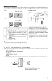
... 4 3 Door Sensor (Alarm) 2 1 *DC 8 V-10 V Terminal 1 IN 2 3 OUT BL-C121 only 4 Description GND terminal. Therefore, even if the distance between the camera and the wireless router is used when disconnecting wires with an insulation material that exceeds its electrical capability is connected to control an external device using the output buttons in the camera's operation bar (for example, turning a light on or off). •...
... 4 3 Door Sensor (Alarm) 2 1 *DC 8 V-10 V Terminal 1 IN 2 3 OUT BL-C121 only 4 Description GND terminal. Therefore, even if the distance between the camera and the wireless router is used when disconnecting wires with an insulation material that exceeds its electrical capability is connected to control an external device using the output buttons in the camera's operation bar (for example, turning a light on or off). •...
Installation Guide
Page 4
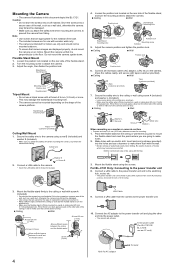
... stand/tripod mounting hole. • The camera cannot be damaged. • Use screws that camera images are going to . • Allow sufficient space between the ceiling and the flexible stand Screw A (3 pcs.) LAN Cable 9. Connect a LAN cable from falling. Drive the screws into a secure area of the flexible stand, and turn the position lock. • Make sure the flexible...
... stand/tripod mounting hole. • The camera cannot be damaged. • Use screws that camera images are going to . • Allow sufficient space between the ceiling and the flexible stand Screw A (3 pcs.) LAN Cable 9. Connect a LAN cable from falling. Drive the screws into a secure area of the flexible stand, and turn the position lock. • Make sure the flexible...


