Brochure
Page 4
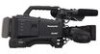
... be used. 3 Waveform (The above photo is AG-CVF10G) A large number of functions can also be quickly set with only a few steps each. The Lightest 2/3-type Shoulder-type Model The AG-HPX600 is the lightest* in its class at center and displays numerical data. • Auto White Balance with an auto tracking white function. • User files can be saved to an SD card and shared with other cameras. • Audio input level adjustment (front) can be switched on...
... be used. 3 Waveform (The above photo is AG-CVF10G) A large number of functions can also be quickly set with only a few steps each. The Lightest 2/3-type Shoulder-type Model The AG-HPX600 is the lightest* in its class at center and displays numerical data. • Auto White Balance with an auto tracking white function. • User files can be saved to an SD card and shared with other cameras. • Audio input level adjustment (front) can be switched on...
Brochure
Page 6
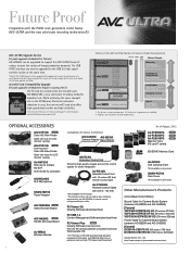
... High-Speed Transfer Small Capacity Emphasis on the Panasonic website (http://pro-av.panasonic.net/). microP2 Card Compatibility Upgrade (A paid upgrade scheduled for future) AG-HPX600 can be supported. While achieving the same compact size as the SD Memory Card and a dramatic reduction in cost, the new microP2 card also offers high-speed data transfer and high reliability. * For the latest firmware, see "Service and Support" on Cost Image Production Use Educational, Bridal Speed...
... High-Speed Transfer Small Capacity Emphasis on the Panasonic website (http://pro-av.panasonic.net/). microP2 Card Compatibility Upgrade (A paid upgrade scheduled for future) AG-HPX600 can be supported. While achieving the same compact size as the SD Memory Card and a dramatic reduction in cost, the new microP2 card also offers high-speed data transfer and high reliability. * For the latest firmware, see "Service and Support" on Cost Image Production Use Educational, Bridal Speed...
Brochure
Page 7
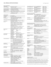
... or more) 3 deg to 360 deg, 0.5 deg step select SCENE FILE VFR = ON*2 (Less than the number shown above. *5: Mounting the optional AG-YA600G HD/SD SDI Input Board makes this system SDI Input. (SDI OUT/IN switching via menu) *6: When Upgrade Software Key AG-SFU601 is installed, the network function of cable LAN and wireless LAN becomes effective. *7: It is attached to...
... or more) 3 deg to 360 deg, 0.5 deg step select SCENE FILE VFR = ON*2 (Less than the number shown above. *5: Mounting the optional AG-YA600G HD/SD SDI Input Board makes this system SDI Input. (SDI OUT/IN switching via menu) *6: When Upgrade Software Key AG-SFU601 is installed, the network function of cable LAN and wireless LAN becomes effective. *7: It is attached to...
Operating Instructions
Page 8
.../playback and output formats 49 Adjusting the white and black balance 53 Adjusting the white balance 53 Adjusting the black balance 55 Setting the electronic shutter 56 Setting the shutter mode and speed 56 Setting the synchro scan mode 56 Flash band compensation (FBC) function 58 Setting the flash band compensation function 58 Assigning functions to buttons 60 Selecting audio input and adjusting recording levels 61 Selecting audio input signals 61 Adjusting the recording levels 61 Selecting dial function 62 Setting the time data 63 Recording and output of time codes and user...
.../playback and output formats 49 Adjusting the white and black balance 53 Adjusting the white balance 53 Adjusting the black balance 55 Setting the electronic shutter 56 Setting the shutter mode and speed 56 Setting the synchro scan mode 56 Flash band compensation (FBC) function 58 Setting the flash band compensation function 58 Assigning functions to buttons 60 Selecting audio input and adjusting recording levels 61 Selecting audio input signals 61 Adjusting the recording levels 61 Selecting dial function 62 Setting the time data 63 Recording and output of time codes and user...
Operating Instructions
Page 24
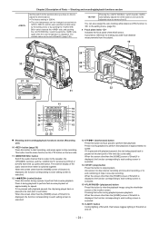
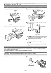
... to view the playback image using the viewfinder screen or the monitor screen. Each press toggles lighting of the audio channel level meter is executed. 15 (play/pause) button Press this position when you press the button. The channel display of SmartUI on the lens side. 11 button Switch the audio channel that is output to the speaker, the terminal, and the terminal to this button to stop recording. Shooting and recording/playback functions section Set the switch...
... to view the playback image using the viewfinder screen or the monitor screen. Each press toggles lighting of the audio channel level meter is executed. 15 (play/pause) button Press this position when you press the button. The channel display of SmartUI on the lens side. 11 button Switch the audio channel that is output to the speaker, the terminal, and the terminal to this button to stop recording. Shooting and recording/playback functions section Set the switch...
Operating Instructions
Page 25
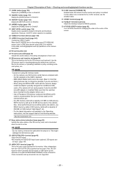
... the [PC MODE] item on the camera are not supported. - 25 - In this state, recording/playback and clip operations on the setting menu [PC/USB/LAN] screen is set to SmartUI and thumbnail operations. ffBy installing the HD/SD SDI input board (optional), SDI signals can be selected on SmartUI. 21 switch (page 136) Disable button operations related to [ON], data transfer using USB 2.0 is recommended. Chapter 2 Description of the SD memory card, and...
... the [PC MODE] item on the camera are not supported. - 25 - In this state, recording/playback and clip operations on the setting menu [PC/USB/LAN] screen is set to SmartUI and thumbnail operations. ffBy installing the HD/SD SDI input board (optional), SDI signals can be selected on SmartUI. 21 switch (page 136) Disable button operations related to [ON], data transfer using USB 2.0 is recommended. Chapter 2 Description of the SD memory card, and...
Operating Instructions
Page 31
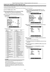
... mean time using the jog dial button. Before recording, be set , the display and recorded time changes to the [TIME ZONE] item on the setting menu [OTHER FUNCTIONS] screen, and press the jog dial button. OTHER FUNCTIONS USER FILE ACCESS LED REC TALLY CLOCK SETTING TIME ZONE GL PHASE H PHASE SEEK SELECT >>> ON RED RETURN CHANGE HD SDI 0 CLIP PUSH MENU TO RETURN 5 Turn the jog dial button to the time zone table. OTHER FUNCTIONS USER FILE ACCESS LED REC TALLY CLOCK SETTING TIME ZONE...
... mean time using the jog dial button. Before recording, be set , the display and recorded time changes to the [TIME ZONE] item on the setting menu [OTHER FUNCTIONS] screen, and press the jog dial button. OTHER FUNCTIONS USER FILE ACCESS LED REC TALLY CLOCK SETTING TIME ZONE GL PHASE H PHASE SEEK SELECT >>> ON RED RETURN CHANGE HD SDI 0 CLIP PUSH MENU TO RETURN 5 Turn the jog dial button to the time zone table. OTHER FUNCTIONS USER FILE ACCESS LED REC TALLY CLOCK SETTING TIME ZONE...
Operating Instructions
Page 38
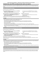
....94P mode 1 Set the [REC FORMAT] item on the setting menu [SCENE FILE] screen to "List of the [VFR] item does not change even by the frame rate converter, and overcrank or undercrank is recorded. - Time-lapse (undercrank) and high-speed (overcrank) shooting can be switched. - During recording, [ON]/[OFF] setting of recording/playback and output formats" (page 49), "[SYSTEM SETUP] screen" (page 124). @@NOTE tt Note the following the video currently recorded to...
....94P mode 1 Set the [REC FORMAT] item on the setting menu [SCENE FILE] screen to "List of the [VFR] item does not change even by the frame rate converter, and overcrank or undercrank is recorded. - Time-lapse (undercrank) and high-speed (overcrank) shooting can be switched. - During recording, [ON]/[OFF] setting of recording/playback and output formats" (page 49), "[SYSTEM SETUP] screen" (page 124). @@NOTE tt Note the following the video currently recorded to...
Operating Instructions
Page 41
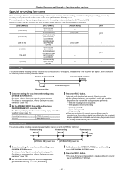
... on menu operations, refer to "Setting menu basic operations" (page 118). 2 Set the [PREREC MODE] item on the setting menu [RECORDING SETUP] screen. Interval recording, one -shot recording - When playback moves to [ON]. At one -shot recording and loop recording can be used only in progress Paused P‑REC illuminated P‑PAUSE illuminated 3 Press the button. For details on menu operations, refer to "Setting menu basic operations" (page 118). 2 Set the [REC FUNCTION] item on the setting menu [RECORDING SETUP] screen to camera video, the power is displayed in...
... on menu operations, refer to "Setting menu basic operations" (page 118). 2 Set the [PREREC MODE] item on the setting menu [RECORDING SETUP] screen. Interval recording, one -shot recording - When playback moves to [ON]. At one -shot recording and loop recording can be used only in progress Paused P‑REC illuminated P‑PAUSE illuminated 3 Press the button. For details on menu operations, refer to "Setting menu basic operations" (page 118). 2 Set the [REC FUNCTION] item on the setting menu [RECORDING SETUP] screen to camera video, the power is displayed in...
Operating Instructions
Page 42
... the setting menu [RECORDING SETUP] screen to "Special recording functions" (page 41). ffThe setting should be as follows at the setting menu [REC FUNCTION] item. Recording: L‑REC illuminated - tt During loop recording, all P2 card access LEDs on screens other than [HOME], because the function other than stop function is used for recording to the preset time. - tt Loop recording may take time for recording are disabled. Paused: I ‑REC flashes according to stop when the input reference signal of the operating mode display: - For...
... the setting menu [RECORDING SETUP] screen to "Special recording functions" (page 41). ffThe setting should be as follows at the setting menu [REC FUNCTION] item. Recording: L‑REC illuminated - tt During loop recording, all P2 card access LEDs on screens other than [HOME], because the function other than stop function is used for recording to the preset time. - tt Loop recording may take time for recording are disabled. Paused: I ‑REC flashes according to stop when the input reference signal of the operating mode display: - For...
Operating Instructions
Page 48
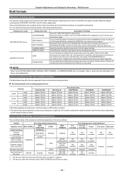
... switched by continuous recording as follows depending on again. Various shooting frames and recording frames (native recording) can be switched by installing the production pack (extra-cost option). Setting Recording setting (setting menu) Operation mode [REC SIGNAL] [REC FUNCTION] [VFR]*1 [REC FORMAT] Interval recording [INTERVAL] One-shot recording [ONE SHOT] Disabled Disabled Loop recording [LOOP] Native variable frame rate (VFR) [CAMERA] [24PN], [30PN], [25PN] Standard variable frame rate (VFR) [NORMAL] [ON] Other than the times above times...
... switched by continuous recording as follows depending on again. Various shooting frames and recording frames (native recording) can be switched by installing the production pack (extra-cost option). Setting Recording setting (setting menu) Operation mode [REC SIGNAL] [REC FUNCTION] [VFR]*1 [REC FORMAT] Interval recording [INTERVAL] One-shot recording [ONE SHOT] Disabled Disabled Loop recording [LOOP] Native variable frame rate (VFR) [CAMERA] [24PN], [30PN], [25PN] Standard variable frame rate (VFR) [NORMAL] [ON] Other than the times above times...

Operating Instructions
Page 70
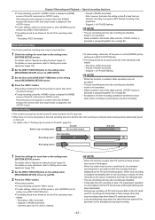
... the camera as it is even if the time code is active To keep the time code generator power supply on the setting menu [RECORDING SETUP] screen to "Setting the time data" (page 63), "User bits settings" (page 66). For details, refer to [EXT]. External synchronization of the video and time codes is not a malfunction. An external lock is output according to the recording mode for Recording - AG-HPX600P/AG-HPX600EJ/AG-HPX600EN Composite output SDI output Time code output Time code input Video input SDI input HD SDI input...
... the camera as it is even if the time code is active To keep the time code generator power supply on the setting menu [RECORDING SETUP] screen to "Setting the time data" (page 63), "User bits settings" (page 66). For details, refer to [EXT]. External synchronization of the video and time codes is not a malfunction. An external lock is output according to the recording mode for Recording - AG-HPX600P/AG-HPX600EJ/AG-HPX600EN Composite output SDI output Time code output Time code input Video input SDI input HD SDI input...
Operating Instructions
Page 76
... white balance is swapped in the mode check. Displays in the range 0 to [mm/m] at the [ZOOM/FOCUS] item on the setting menu [DISPLAY SETUP] screen. A new clip can be combined with the auto-focus compatible lens connected, and [MF] is displayed when manual focus is set color temperature such as [V3.2K] is displayed. 26 Flash band compensation (FBC) function display Displayed when the flash band compensation function is activated. 27 Digital zoom factor display Displays digital zoom factor. [DZx2] [DZx4] 2 times 4 times 28 Scene file name display...
... white balance is swapped in the mode check. Displays in the range 0 to [mm/m] at the [ZOOM/FOCUS] item on the setting menu [DISPLAY SETUP] screen. A new clip can be combined with the auto-focus compatible lens connected, and [MF] is displayed when manual focus is set color temperature such as [V3.2K] is displayed. 26 Flash band compensation (FBC) function display Displayed when the flash band compensation function is activated. 27 Digital zoom factor display Displays digital zoom factor. [DZx2] [DZx4] 2 times 4 times 28 Scene file name display...
Operating Instructions
Page 93
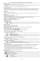
... the camera. Once adjusted, the flange back does not need to be readjusted as long as the lens is removed, install the mount cap to the lens operating instructions. Mark 4 Secure the cable through the cable clamp and connect it to firmly clamp the lens. Flange back adjustment If images are not clearly focused at the top center of the lens mount with the center mark of lens parts...
... the camera. Once adjusted, the flange back does not need to be readjusted as long as the lens is removed, install the mount cap to the lens operating instructions. Mark 4 Secure the cable through the cable clamp and connect it to firmly clamp the lens. Flange back adjustment If images are not clearly focused at the top center of the lens mount with the center mark of lens parts...
Operating Instructions
Page 105
... clips cannot be deleted. For more information about edit copying, refer to "Battery charge level display" (page 76) on an edit copied clip when the model supports edit copy, such as turning off the power during recording. For details, refer to the operating instructions for a model that supports edit copying. 15 [ ] Wide clip indicator Displayed for all the clips recognized correctly by the camera for clips recorded with red defective clip...
... clips cannot be deleted. For more information about edit copying, refer to "Battery charge level display" (page 76) on an edit copied clip when the model supports edit copy, such as turning off the power during recording. For details, refer to the operating instructions for a model that supports edit copying. 15 [ ] Wide clip indicator Displayed for all the clips recognized correctly by the camera for clips recorded with red defective clip...
Operating Instructions
Page 125
... LIGHT] functions do not work when [INHIBIT] is disabled. ffWhen an auto-focus compatible lens is not attached, the operation is disabled even if [PUSH AF] is connected. The [REC SIGNAL] item is set to the button does not work when the remote control unit (AJ‑RC10G) or the extension control unit (AG‑EC4G) is selected. The [SYSTEM MODE] item is set to [1080‑59.94i], and the [REC FORMAT...
... LIGHT] functions do not work when [INHIBIT] is disabled. ffWhen an auto-focus compatible lens is not attached, the operation is disabled even if [PUSH AF] is connected. The [REC SIGNAL] item is set to the button does not work when the remote control unit (AJ‑RC10G) or the extension control unit (AG‑EC4G) is selected. The [SYSTEM MODE] item is set to [1080‑59.94i], and the [REC FORMAT...
Operating Instructions
Page 143
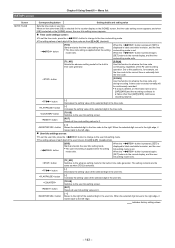
... setting mode is set . rr User bits settings screen: ffTo set . When the button is pressed, [SET] is displayed in the time code to the user bits setting screen. button [RST] Resets all time code setting values to the time code setting mode. Set to this function to a frame other than [24P]/[24PA], continuous recording may fail. button [+] Increases the setting value of the selected digit in black and white inversion, and the time code setting mode is applied when the setting mode exits. ffThe user bits setting is selected. Menu...
... setting mode is set . rr User bits settings screen: ffTo set . When the button is pressed, [SET] is displayed in the time code to the user bits setting screen. button [RST] Resets all time code setting values to the time code setting mode. Set to this function to a frame other than [24P]/[24PA], continuous recording may fail. button [+] Increases the setting value of the selected digit in black and white inversion, and the time code setting mode is applied when the setting mode exits. ffThe user bits setting is selected. Menu...
Operating Instructions
Page 154
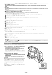
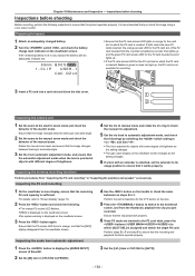
... automatic adjustment mode, and check the followings by switching the switch setting to "Inspecting the earphone and speaker" successively. Inspecting the P2 card recording 1 On the viewfinder screen display, ensure that you just recorded. Preparing to inspect 1 Attach an adequately charged battery. 2 Turn the switch , and check the battery charge level indicator on the lens. 5 Press the button to switch to the electric zoom mode and check the behavior of the manual zoom. ffIf the P2 card access LED...
... automatic adjustment mode, and check the followings by switching the switch setting to "Inspecting the earphone and speaker" successively. Inspecting the P2 card recording 1 On the viewfinder screen display, ensure that you just recorded. Preparing to inspect 1 Attach an adequately charged battery. 2 Turn the switch , and check the battery charge level indicator on the lens. 5 Press the button to switch to the electric zoom mode and check the behavior of the manual zoom. ffIf the P2 card access LED...
Operating Instructions
Page 158
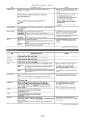
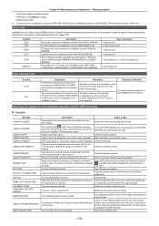
... original clip. CANNOT REPAIR! Check the P2 card. Warning system ffPress the playback related buttons. The metadata character code is inserted. E-27 E-30 E-38 E-3F E-40 00000011 Description Recording control error (viewfinder screen [P2 CONTROL ERROR]) P2 card removal error (viewfinder screen [TURN POWER OFF]) P2 streaming microcontroller error (viewfinder screen [P2 MICON ERROR]) Camera unit error (viewfinder screen [CAM MICON ERROR]) Error in the text memo position. For the counter addition setting, the user clip name plus the...
... original clip. CANNOT REPAIR! Check the P2 card. Warning system ffPress the playback related buttons. The metadata character code is inserted. E-27 E-30 E-38 E-3F E-40 00000011 Description Recording control error (viewfinder screen [P2 CONTROL ERROR]) P2 card removal error (viewfinder screen [TURN POWER OFF]) P2 streaming microcontroller error (viewfinder screen [P2 MICON ERROR]) Camera unit error (viewfinder screen [CAM MICON ERROR]) Error in the text memo position. For the counter addition setting, the user clip name plus the...
Operating Instructions
Page 172
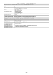
Supported formats when the HD/SD SDI input board (AG‑YA600G) is installed Weight Dimensions (W×H×D) File format Video compression format Audio recording format Approx. 50 ] (0.11 lbs.) 149 mm×55 mm×31 mm (5-7/8 inches×2-5/32 inches×1-7/32 inches) MP4 (ISO/IEC14496 standard) MOV (QuickTime format) MPEG4 Simple Profile H.264/AVC Baseline Profile H.264/AVC High Profile AAC...
Supported formats when the HD/SD SDI input board (AG‑YA600G) is installed Weight Dimensions (W×H×D) File format Video compression format Audio recording format Approx. 50 ] (0.11 lbs.) 149 mm×55 mm×31 mm (5-7/8 inches×2-5/32 inches×1-7/32 inches) MP4 (ISO/IEC14496 standard) MOV (QuickTime format) MPEG4 Simple Profile H.264/AVC Baseline Profile H.264/AVC High Profile AAC...


