Brochure
Page 3
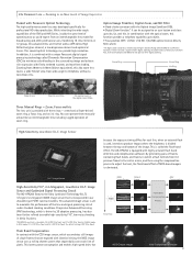
... to produce images where the brightness is set to maximize the performance of frames containing flash bands, and frames in our shoulder-type P2HD camera recorders. Focus Ring Zoom Ring Iris Ring Wide 28 mm Tele 616 mm (22x) 22x optical zoom x 10x digital zoom (220x) Three Manual Rings - a mechanical (cam-driven) zoom ring, a focus ring, and an iris ring. Zooming in on New Levels of operating ease...
... to produce images where the brightness is set to maximize the performance of frames containing flash bands, and frames in our shoulder-type P2HD camera recorders. Focus Ring Zoom Ring Iris Ring Wide 28 mm Tele 616 mm (22x) 22x optical zoom x 10x digital zoom (220x) Three Manual Rings - a mechanical (cam-driven) zoom ring, a focus ring, and an iris ring. Zooming in on New Levels of operating ease...
Brochure
Page 8
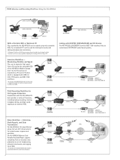
... viewing software (available free of charge) installed. * For details, see the rear cover page (Notes Regarding the Handling of IT infrastructures for AVCHD file conversion and output. AG-HPX250 7 P2 card (Blank) HD SDI AJ-HPM200 P2/AVCHD* File P2 card (Recorded) USB 2.0 e-SATA HDD FPU Internet NLE/Server HDD Or, a notebook PC* can be copied using only a portable HDD. AG-HPX250 P2 card (Blank) HD SDI P2 card (Recorded) LCD Monitor USB 3.0 AG-HPD24 HDD HDD...
... viewing software (available free of charge) installed. * For details, see the rear cover page (Notes Regarding the Handling of IT infrastructures for AVCHD file conversion and output. AG-HPX250 7 P2 card (Blank) HD SDI AJ-HPM200 P2/AVCHD* File P2 card (Recorded) USB 2.0 e-SATA HDD FPU Internet NLE/Server HDD Or, a notebook PC* can be copied using only a portable HDD. AG-HPX250 P2 card (Blank) HD SDI P2 card (Recorded) LCD Monitor USB 3.0 AG-HPD24 HDD HDD...
Brochure
Page 11
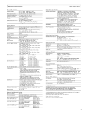
...: OFF, 1/4, 1/16, 1/64 Minimum Shooting Distance: Approx. 1 m Hood: Large-sized lens hood with button-type battery, Microphone holder, Eye cup, Shoulder strap, P2 card driver software install CD-ROM *1: The Recording/playback times listed left figures somewhat. *2: AG-HPX250EJ does not support input via menu Pin jack × 2 (CH1/CH2), Output: 316 mV, 600 Ω ø3.5 mm stereo mini jack × 1 Other Input/Output TC IN/OUT: Camera Remote: IEEE 1394*2: USB 2.0 (DEVICE)*2: USB 2.0 (HOST)*2: BNC× 1, IN...
...: OFF, 1/4, 1/16, 1/64 Minimum Shooting Distance: Approx. 1 m Hood: Large-sized lens hood with button-type battery, Microphone holder, Eye cup, Shoulder strap, P2 card driver software install CD-ROM *1: The Recording/playback times listed left figures somewhat. *2: AG-HPX250EJ does not support input via menu Pin jack × 2 (CH1/CH2), Output: 316 mV, 600 Ω ø3.5 mm stereo mini jack × 1 Other Input/Output TC IN/OUT: Camera Remote: IEEE 1394*2: USB 2.0 (DEVICE)*2: USB 2.0 (HOST)*2: BNC× 1, IN...
Operating Instructions
Page 4
...Using the LCD monitor 7 Emphasizing Image Outlines 7 Adjusting the screen display 8 Changing backlight brightness 8 Tally lamp 9 Basic shooting operations 10 Preparing to shoot 10 Shooting in auto mode 10 Checking photos taken (REC CHECK 12 P2 card access lamps 12 Protecting against a possible erasure 12 Formatting P2 cards 13 P2 card recording times 14 Remove the P2 card 15 Using SD/SDHC memory cards 16 Installing and removing the SD memory card 16 Formatting SD memory card 16 Cautions in using SD memory cards 17 Using the zoom function 18 Digital zoom function 19 Shooting...
...Using the LCD monitor 7 Emphasizing Image Outlines 7 Adjusting the screen display 8 Changing backlight brightness 8 Tally lamp 9 Basic shooting operations 10 Preparing to shoot 10 Shooting in auto mode 10 Checking photos taken (REC CHECK 12 P2 card access lamps 12 Protecting against a possible erasure 12 Formatting P2 cards 13 P2 card recording times 14 Remove the P2 card 15 Using SD/SDHC memory cards 16 Installing and removing the SD memory card 16 Formatting SD memory card 16 Cautions in using SD memory cards 17 Using the zoom function 18 Digital zoom function 19 Shooting...
Operating Instructions
Page 5
... meta data 87 Formatting a P2 card 91 Formatting SD memory cards 92 Setting the thumbnail display mode 92 Properties 93 Useful playback functions 99 Variable speed search 99 Slow playback 99 Fast forward/rewind playback 99 Frame-by-frame playback 99 Clip skip 100 Adjusting the volume 100 Viewing images on a TV/monitor 100 Checking the date and time 100 Editing Connecting external units 101 Headphones 101 External microphone 101 Personal computer (non-linear editing/file transfer 102 Hard disk drive (data copying 102 Digital video equipment...
... meta data 87 Formatting a P2 card 91 Formatting SD memory cards 92 Setting the thumbnail display mode 92 Properties 93 Useful playback functions 99 Variable speed search 99 Slow playback 99 Fast forward/rewind playback 99 Frame-by-frame playback 99 Clip skip 100 Adjusting the volume 100 Viewing images on a TV/monitor 100 Checking the date and time 100 Editing Connecting external units 101 Headphones 101 External microphone 101 Personal computer (non-linear editing/file transfer 102 Hard disk drive (data copying 102 Digital video equipment...
Operating Instructions
Page 38
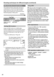
... instant. • Resolution decreases in video exposed to flash light. • Horizontal lines appear in video footage exposed to a USER button. When you wish to use this mode again, set to one not shown in "FBC operation enabled mode". CL I - The FBC function returns to OFF. • Shutter OFF • Digital zoom OFF 38 Time flow Flash light Image recorded (FBC off . PAUSE 1 - In some shooting environments adequate FBC effect may not...
... instant. • Resolution decreases in video exposed to flash light. • Horizontal lines appear in video footage exposed to a USER button. When you wish to use this mode again, set to one not shown in "FBC operation enabled mode". CL I - The FBC function returns to OFF. • Shutter OFF • Digital zoom OFF 38 Time flow Flash light Image recorded (FBC off . PAUSE 1 - In some shooting environments adequate FBC effect may not...
Operating Instructions
Page 42
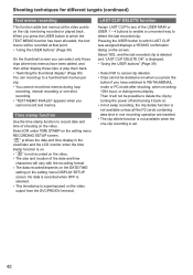
... the setting menu DISPLAY SETUP screen. " R " prefixes the date and time display in one recording operation are inserted. • The clip delete function is not available when the one -shot recording. • "TEXT MEMO INVALID" appears when you cannot record text memos. LAST CLIP DELETE function Assign LAST CLIP to any of the USER MAIN or USER 1 - 4 buttons to enable a convenient way to delete the clip by turning the power off and turning...
... the setting menu DISPLAY SETUP screen. " R " prefixes the date and time display in one recording operation are inserted. • The clip delete function is not available when the one -shot recording. • "TEXT MEMO INVALID" appears when you cannot record text memos. LAST CLIP DELETE function Assign LAST CLIP to any of the USER MAIN or USER 1 - 4 buttons to enable a convenient way to delete the clip by turning the power off and turning...
Operating Instructions
Page 44
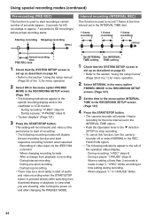
... start of audio and video recording when the START/STOP button is pressed directly after changing the PREREC MODE. Starting recording Stopping recording (time) Interval recording (INTERVAL REC) This function is used to view what you are shooting, after turning the power on and after switching from thumbnail display or playback to start recording a certain number of seconds (approx. 3 seconds for HD recordings or approx. 7 seconds for menu operation. 2 Select ON in the menu option PREREC MODE in the RECORDING SETUP screen. (Page...
... start of audio and video recording when the START/STOP button is pressed directly after changing the PREREC MODE. Starting recording Stopping recording (time) Interval recording (INTERVAL REC) This function is used to view what you are shooting, after turning the power on and after switching from thumbnail display or playback to start recording a certain number of seconds (approx. 3 seconds for HD recordings or approx. 7 seconds for menu operation. 2 Select ON in the menu option PREREC MODE in the RECORDING SETUP screen. (Page...
Operating Instructions
Page 54
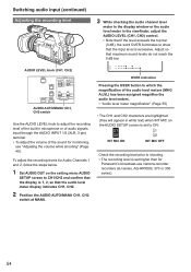
... microphone or of audio signals input through the AUDIO INPUT 1/2 (XLR, 3 pin) terminal. • To adjust the volume of the built-in white text) when INT MIC on the setting menu AUDIO SETUP screen to CH1/CH2 and confirm that the display is 1, 2, so that the audio level meter display indicates CH1, CH2. 2 Position the AUDIO AUTO/MANU CH1, CH2 switch at MANU. 3 While checking the audio channel level meter in the display window or the audio level...
... microphone or of audio signals input through the AUDIO INPUT 1/2 (XLR, 3 pin) terminal. • To adjust the volume of the built-in white text) when INT MIC on the setting menu AUDIO SETUP screen to CH1/CH2 and confirm that the display is 1, 2, so that the audio level meter display indicates CH1, CH2. 2 Position the AUDIO AUTO/MANU CH1, CH2 switch at MANU. 3 While checking the audio channel level meter in the display window or the audio level...
Operating Instructions
Page 57
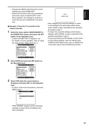
... scene file settings to their factory defaults, select INITIAL in step 2 and perform the operation described in step 3. • To save and read user file settings or return them to their factory defaults, open the setting menu OTHER FUNCTIONS screen and run USER FILE in the SCENE FILE screen, then press the SET button on the Operation lever. • Comfirm SCENE FILE F3 display or not. • For details on menu operation, refer to "Using the setup...
... scene file settings to their factory defaults, select INITIAL in step 2 and perform the operation described in step 3. • To save and read user file settings or return them to their factory defaults, open the setting menu OTHER FUNCTIONS screen and run USER FILE in the SCENE FILE screen, then press the SET button on the Operation lever. • Comfirm SCENE FILE F3 display or not. • For details on menu operation, refer to "Using the setup...
Operating Instructions
Page 61
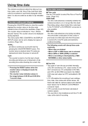
... as data in the DISPLAY SETUP screen can be set to keep track of clip recording time while shooting the current clip. • Pressing the RESET button when the counter value is interrupted by pressing the COUNTER RESET button. The menu option REC COUNTER in clip metadata files. Recording using a slave-locked time code input to the TC IN/OUT or DVCPRO/DV connectors is turned off or new P2 cards are deleted...
... as data in the DISPLAY SETUP screen can be set to keep track of clip recording time while shooting the current clip. • Pressing the RESET button when the counter value is interrupted by pressing the COUNTER RESET button. The menu option REC COUNTER in clip metadata files. Recording using a slave-locked time code input to the TC IN/OUT or DVCPRO/DV connectors is turned off or new P2 cards are deleted...
Operating Instructions
Page 62
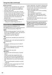
... user bit year, date and time, but also to set file creation dates when clips are retained after the power is necessary to set TC IN/ OUT SEL on the setting menu OUTPUT SEL screen to TC IN. 62 Using time data (continued) ■ Date (real time) • The built-in clock calculates the year, month, day and time from the internal clock to display on video in the LCD, viewfinder and VIDEO...
... user bit year, date and time, but also to set file creation dates when clips are retained after the power is necessary to set TC IN/ OUT SEL on the setting menu OUTPUT SEL screen to TC IN. 62 Using time data (continued) ■ Date (real time) • The built-in clock calculates the year, month, day and time from the internal clock to display on video in the LCD, viewfinder and VIDEO...
Operating Instructions
Page 66
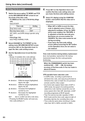
... CHANGE for video output. • At a frame rate (capture frame rate) of 24P in 24PN mode, the speed of recording and the output time code matches actual time, but not at start of the time code in Rec Run mode and the time code output at any time code setting to 0. 4 Press SET on the Operation lever and confirm the time code setting value and you leave the time code setting screen without pressing the SET button on the Operation lever to open the time code setting screen. 3 Use...
... CHANGE for video output. • At a frame rate (capture frame rate) of 24P in 24PN mode, the speed of recording and the output time code matches actual time, but not at start of the time code in Rec Run mode and the time code output at any time code setting to 0. 4 Press SET on the Operation lever and confirm the time code setting value and you leave the time code setting screen without pressing the SET button on the Operation lever to open the time code setting screen. 3 Use...
Operating Instructions
Page 78
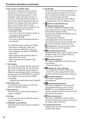
... displayed on a proxy supporting P2 camera recorder such as follows: • Other than one of all the clips recognised correctly by shooting dates and times. The numbers of different recording formats, they contain P2 cards. Time Display You can be deleted. For more than the USB HOST mode: gray • Not connected in USB HOST mode: gray • HDD recognized and usable in USB HOST mode: white • HDD recognized and thumbnails shown in USB...
... displayed on a proxy supporting P2 camera recorder such as follows: • Other than one of all the clips recognised correctly by shooting dates and times. The numbers of different recording formats, they contain P2 cards. Time Display You can be deleted. For more than the USB HOST mode: gray • Not connected in USB HOST mode: gray • HDD recognized and usable in USB HOST mode: white • HDD recognized and thumbnails shown in USB...
Operating Instructions
Page 109
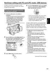
... camera enters PC mode, and video/audio output stops. • You cannot switch to the USB 2.0 connector. A USB 2.0 cable is not displayed when operating as mass storage. For details, refer to the installation manual. 2 Select USB Device in the camerarecorder as a USB device, and video/audio cannot be installed on the computer. Procedures for menu operation. Select the "AG-HPX250" driver. Leaves the thumbnail screen of Vol. 1) for making connections to a personal computer 4 Turn the POWER/MODE switch to the MODE position...
... camera enters PC mode, and video/audio output stops. • You cannot switch to the USB 2.0 connector. A USB 2.0 cable is not displayed when operating as mass storage. For details, refer to the installation manual. 2 Select USB Device in the camerarecorder as a USB device, and video/audio cannot be installed on the computer. Procedures for menu operation. Select the "AG-HPX250" driver. Leaves the thumbnail screen of Vol. 1) for making connections to a personal computer 4 Turn the POWER/MODE switch to the MODE position...

Operating Instructions
Page 132
... display. LOAD: Loads data stored in camera-recorder memory. F6 scene file). SAVE: Saves current values in camera-recorder memory. "Setting SYNCHRO SCAN mode" (Page 50) 1/60.0 (AG-HPX250P) 1/50.0 (AG-HPX250EN) Adjusts the level of image outline correction (in horizontal and vertical directions). - 7 ...0 *1... +7 Adjusts the level of the scene file assigned to F1. ___indicates the factory setting. 132 sec: Displays the shutter speed in blue when not set a shutter speed. • Set values (displayed values) are switched. • Displayed in fractions. Enables or disables...
... display. LOAD: Loads data stored in camera-recorder memory. F6 scene file). SAVE: Saves current values in camera-recorder memory. "Setting SYNCHRO SCAN mode" (Page 50) 1/60.0 (AG-HPX250P) 1/50.0 (AG-HPX250EN) Adjusts the level of image outline correction (in horizontal and vertical directions). - 7 ...0 *1... +7 Adjusts the level of the scene file assigned to F1. ___indicates the factory setting. 132 sec: Displays the shutter speed in blue when not set a shutter speed. • Set values (displayed values) are switched. • Displayed in fractions. Enables or disables...
Operating Instructions
Page 146
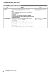
... all times. TCG/TCR: Outputs time code generator value during camerarecorder recording and outputs the played back time code during video playback. Setup menu list (continued) OUTPUT SEL screen (continued) Item TC OUT TC VIDEO SYNC Setting Notes Sets the time code type output when TC IN/OUT connector is connected as TC OUT. VIDEO OUT: Outputs the time code in line with no delay. TCG: Outputs the time code generator value of video output from the VIDEO OUT connector. ___indicates the factory setting. 146...
... all times. TCG/TCR: Outputs time code generator value during camerarecorder recording and outputs the played back time code during video playback. Setup menu list (continued) OUTPUT SEL screen (continued) Item TC OUT TC VIDEO SYNC Setting Notes Sets the time code type output when TC IN/OUT connector is connected as TC OUT. VIDEO OUT: Outputs the time code in line with no delay. TCG: Outputs the time code generator value of video output from the VIDEO OUT connector. ___indicates the factory setting. 146...
Operating Instructions
Page 157
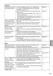
...; The battery in the remote control may have connected Read the television's instructions carefully and select the the camera-recorder correct video input connector for the camera-recorder. If the remote control fails to work even if it means that make when the camera- This is not, format the card in ONE (Page 86) CLIP REC mode. Adjust the volume level using the PAGE/AUDIO MON/VAR button+. (Page 100) Cannot perform hot swap playback. •...
...; The battery in the remote control may have connected Read the television's instructions carefully and select the the camera-recorder correct video input connector for the camera-recorder. If the remote control fails to work even if it means that make when the camera- This is not, format the card in ONE (Page 86) CLIP REC mode. Adjust the volume level using the PAGE/AUDIO MON/VAR button+. (Page 100) Cannot perform hot swap playback. •...
Operating Instructions
Page 165
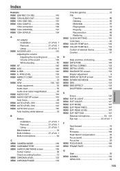
...-in microphone 52 C MENU CAMERA MODE 136 MENU CARD&BATTERY 149 MENU CARD FUNCTIONS screen 150 Center marker 36 Check recording function 12 MENU CHROMA LEVEL 133 MENU CHROMA PHASE 133 Cine-like gamma 23 Clip Copying 86 Deleting 84 Meta data 87 Playing back 79 Property 93 Reconnection 85 Restoring 85 MENU CLOCK SETTING 151 Color bars 40 MENU COLOR TEMP Ach 133 MENU COLOR TEMP Bch 133 Control of external device 106 Counter 61 D Date and time of shooting 100 MENU DATE/TIME 148 MENU DETAIL...
...-in microphone 52 C MENU CAMERA MODE 136 MENU CARD&BATTERY 149 MENU CARD FUNCTIONS screen 150 Center marker 36 Check recording function 12 MENU CHROMA LEVEL 133 MENU CHROMA PHASE 133 Cine-like gamma 23 Clip Copying 86 Deleting 84 Meta data 87 Playing back 79 Property 93 Reconnection 85 Restoring 85 MENU CLOCK SETTING 151 Color bars 40 MENU COLOR TEMP Ach 133 MENU COLOR TEMP Bch 133 Control of external device 106 Counter 61 D Date and time of shooting 100 MENU DATE/TIME 148 MENU DETAIL...
Understanding P2 Workflow: Avid Xpress Pro HD
Page 2
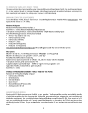
... and software requirements, acquisition techniques, archiving in the field Shooting with Avid Xpress Pro HD. You must have been tested by Avid. Windows Media Player 10 (9.5 codecs) 1 GB system memory minimum, 2 GB recommended for this paper: Panasonic CF-51 Toughbook laptop computer: • Intel Core Duo 1.67 GHz • 60 GB hard drive • DVD-CD-RW Drive • Quick Time 7.1 • Microsoft Windows...
... and software requirements, acquisition techniques, archiving in the field Shooting with Avid Xpress Pro HD. You must have been tested by Avid. Windows Media Player 10 (9.5 codecs) 1 GB system memory minimum, 2 GB recommended for this paper: Panasonic CF-51 Toughbook laptop computer: • Intel Core Duo 1.67 GHz • 60 GB hard drive • DVD-CD-RW Drive • Quick Time 7.1 • Microsoft Windows...


