Owner Manual
Page 1
Please retain this manual thoroughly before making any connections and plugging it in this manual will enable you for future reference. Contents Introduction 2 Connections 20 First Time Setup 38 Basic Operations 51 Advanced Operations 64 Advanced Setup 68 Zone 2 74 Controlling Other Components ....78 Specifications 83 Troubleshooting 84 En Please read this manual for purchasing an Onkyo AV Receiver. Following the instructions in . AV Receiver TX-SR603X Instruction Manual Thank you to obtain optimum performance and listening enjoyment from your new AV Receiver.
Please retain this manual thoroughly before making any connections and plugging it in this manual will enable you for future reference. Contents Introduction 2 Connections 20 First Time Setup 38 Basic Operations 51 Advanced Operations 64 Advanced Setup 68 Zone 2 74 Controlling Other Components ....78 Specifications 83 Troubleshooting 84 En Please read this manual for purchasing an Onkyo AV Receiver. Following the instructions in . AV Receiver TX-SR603X Instruction Manual Thank you to obtain optimum performance and listening enjoyment from your new AV Receiver.

Owner Manual
Page 4
...and that is protected by ASTA or BSI to BS1362. IMPORTANT A 5 or 13 ampere fuse is fitted in this instruction manual is in compliance with the corresponding technical standards such as follows: The wire which is coloured blue must be connected to the terminal ...Cable Speaker cable labels * In catalogs and on the body of the fuse. GROEBENZELL, GERMANY I. The wire which is approved by U.S. MORI ONKYO EUROPE ELECTRONICS GmbH This product incorporates copyright protection technology that it is coloured brown must be connected to the terminal which is prohibited. Use this...
...and that is protected by ASTA or BSI to BS1362. IMPORTANT A 5 or 13 ampere fuse is fitted in this instruction manual is in compliance with the corresponding technical standards such as follows: The wire which is coloured blue must be connected to the terminal ...Cable Speaker cable labels * In catalogs and on the body of the fuse. GROEBENZELL, GERMANY I. The wire which is approved by U.S. MORI ONKYO EUROPE ELECTRONICS GmbH This product incorporates copyright protection technology that it is coloured brown must be connected to the terminal which is prohibited. Use this...

Owner Manual
Page 8
... This sensor receives control signals from the remote controller. N TUNING MODE button (54) This button is used to select the Auto or Manual tuning mode. C ZONE 2/OFF button (76) The ZONE 2 button is used to the previously displayed onscreen setup menu. B ZONE ...;nd the main explanation for Zone 2. H LISTENING MODE [ ] [ ] buttons (60) These buttons are used to select the listening modes. Front & Rear Panels Front Panel TX-SR603X 1 234 5 6 7 8 9 0 A B C DE FG H STANDBY/ON ZONE2 OFF ZONE 2 LEVEL PHONES TUNING / PRESET MASTER VOLUME STANDBY TONE + DISPLAY MULTl CH...
... This sensor receives control signals from the remote controller. N TUNING MODE button (54) This button is used to select the Auto or Manual tuning mode. C ZONE 2/OFF button (76) The ZONE 2 button is used to the previously displayed onscreen setup menu. B ZONE ...;nd the main explanation for Zone 2. H LISTENING MODE [ ] [ ] buttons (60) These buttons are used to select the listening modes. Front & Rear Panels Front Panel TX-SR603X 1 234 5 6 7 8 9 0 A B C DE FG H STANDBY/ON ZONE2 OFF ZONE 2 LEVEL PHONES TUNING / PRESET MASTER VOLUME STANDBY TONE + DISPLAY MULTl CH...

Owner Manual
Page 10
... This area of digital input signals. 4 Tuning indicators (54) TUNED: This indicator lights up when the Auto Tuning mode is selected, and disappears when the Manual Tuning mode is selected. 10 FM STEREO: This indicator lights up when the AV receiver is tuned to a stereo FM station. 5 SLEEP indicator (52) This...
... This area of digital input signals. 4 Tuning indicators (54) TUNED: This indicator lights up when the Auto Tuning mode is selected, and disappears when the Manual Tuning mode is selected. 10 FM STEREO: This indicator lights up when the AV receiver is tuned to a stereo FM station. 5 SLEEP indicator (52) This...

Owner Manual
Page 14
... a CD player, MD player, or CD recorder made by another manufacturer (see page 80 Note: Some of the remote controller operations described in this manual may not work as expected with each type of component. To set the remote controller to nine different components. CD TAPE TUNER 7 8 9 T ... using the eight REMOTE MODE buttons. RECEIVER/TAPE Mode RECEIVER/TAPE mode is for use with other manufacturers (see page 78). It can control an Onkyo CD recorder, or a cable TV receiver. A B C D RECEIVER 5 F G H I 1 J K 2 ON STANDBY I HDD Mode This mode is used to control up to ...
... a CD player, MD player, or CD recorder made by another manufacturer (see page 80 Note: Some of the remote controller operations described in this manual may not work as expected with each type of component. To set the remote controller to nine different components. CD TAPE TUNER 7 8 9 T ... using the eight REMOTE MODE buttons. RECEIVER/TAPE Mode RECEIVER/TAPE mode is for use with other manufacturers (see page 78). It can control an Onkyo CD recorder, or a cable TV receiver. A B C D RECEIVER 5 F G H I 1 J K 2 ON STANDBY I HDD Mode This mode is used to control up to ...

Owner Manual
Page 18
D ALBUM +/- E DISPLAY button* This button turns on the backlight for controlling Onkyo's next generation HDD-compatible components. G Pause [ ] button This button pauses playback on the HDD-compatible component. L Play [ ] button This button starts playback on ... This button selects the next song on the HDD-compatible component. P RANDOM button* This button sets the Shuffle function to the DS-A1's instruction manual. Remote Controller-Continued HDD Mode HDD mode is for 30 seconds on the HDD-compatible component. CD TAPE TUNER 7 8 9 T V VOL +10 0 CLEAR - - /- - - 10...
D ALBUM +/- E DISPLAY button* This button turns on the backlight for controlling Onkyo's next generation HDD-compatible components. G Pause [ ] button This button pauses playback on the HDD-compatible component. L Play [ ] button This button starts playback on ... This button selects the next song on the HDD-compatible component. P RANDOM button* This button sets the Shuffle function to the DS-A1's instruction manual. Remote Controller-Continued HDD Mode HDD mode is for 30 seconds on the HDD-compatible component. CD TAPE TUNER 7 8 9 T V VOL +10 0 CLEAR - - /- - - 10...

Owner Manual
Page 20
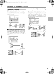
... plugs to connect DVD players with your other video equipment. Connecting the AV Receiver About AV Connections • Before making any AV connections, read the manuals supplied with a 5.1-channel analog audio output. Wrong! Composite video is the same as for coaxial. AV Cables & Jacks AV Connection Color Coding RCA-type AV...
... plugs to connect DVD players with your other video equipment. Connecting the AV Receiver About AV Connections • Before making any AV connections, read the manuals supplied with a 5.1-channel analog audio output. Wrong! Composite video is the same as for coaxial. AV Cables & Jacks AV Connection Color Coding RCA-type AV...

Owner Manual
Page 30
... the other IR IN DIGITAL COAXIAL IN 1 IN 2 OPTICAL IN 1 12 V TRIGGER OUT ZONE 2 COMPONENT VIDEO IN 3 IN 2 IN 1 OUT Y PB AV RECEIVER MODEL NO. TX-SR 603X ANTENNA AM VIDEO 3 VIDEO 2 FM 75 VIDEO 1 PR IN 2 IN OUT IN OUT IN IN 3 IN OUT IN IN OUT IN OUT IN... an S-Video output on your TV or playback VCR, as shown. Notes: • The AV receiver must be recorded via composite video outputs. See the manuals supplied with your TV or playback VCR. Use another S-Video cable to connect the AV receiver's S VIDEO 3 IN jack to an S-Video output. back VCR...
... the other IR IN DIGITAL COAXIAL IN 1 IN 2 OPTICAL IN 1 12 V TRIGGER OUT ZONE 2 COMPONENT VIDEO IN 3 IN 2 IN 1 OUT Y PB AV RECEIVER MODEL NO. TX-SR 603X ANTENNA AM VIDEO 3 VIDEO 2 FM 75 VIDEO 1 PR IN 2 IN OUT IN OUT IN IN 3 IN OUT IN IN OUT IN OUT IN... an S-Video output on your TV or playback VCR, as shown. Notes: • The AV receiver must be recorded via composite video outputs. See the manuals supplied with your TV or playback VCR. Use another S-Video cable to connect the AV receiver's S VIDEO 3 IN jack to an S-Video output. back VCR...
Owner Manual
Page 35
... IN DIGITAL COAXIAL IN 1 IN 2 OPTICAL IN 1 12 V TRIGGER OUT ZONE 2 COMPONENT VIDEO IN 3 IN 2 IN 1 OUT Y PB AV RECEIVER MODEL NO. TX-SR 603X ANTENNA AM VIDEO 3 VIDEO 2 FM 75 VIDEO 1 PR IN 2 ZONE 2 SPEAKERS L MONITOR DVD OUT V L R R S IN OUT IN OUT IN... MC head amp or MC transformer AUDIO OUTPUT L AUDIO INPUT L R R AUDIO OUTPUT L R AUDIO INPUT L R 35 For further information, see the manual for your turntable or phono preamp. Connecting the AV Receiver-Continued Connecting a Turntable I Turntable with an MC (Moving Coil) Cartridge Use an analog audio cable...
... IN DIGITAL COAXIAL IN 1 IN 2 OPTICAL IN 1 12 V TRIGGER OUT ZONE 2 COMPONENT VIDEO IN 3 IN 2 IN 1 OUT Y PB AV RECEIVER MODEL NO. TX-SR 603X ANTENNA AM VIDEO 3 VIDEO 2 FM 75 VIDEO 1 PR IN 2 ZONE 2 SPEAKERS L MONITOR DVD OUT V L R R S IN OUT IN OUT IN... MC head amp or MC transformer AUDIO OUTPUT L AUDIO INPUT L R R AUDIO OUTPUT L R AUDIO INPUT L R 35 For further information, see the manual for your turntable or phono preamp. Connecting the AV Receiver-Continued Connecting a Turntable I Turntable with an MC (Moving Coil) Cartridge Use an analog audio cable...

Owner Manual
Page 36
... function will not work properly, you must make good connections. • Use only cables for connections. TX-SR 603X ANTENNA AM VIDEO 3 VIDEO 2 FM 75 VIDEO 1 PR IN 2 ZONE 2 SPEAKERS MONITOR... AUDIO OUTPUT L R e.g., DVD player e.g., MD recorder Notes: • If you connect an -compatible Onkyo MiniDisc recorder or CD recorder to the TAPE IN/OUT jacks, for to work if the component's power cord...is set to Standby, all functions. No cables are connected digitally. Refer to the manuals supplied with your components. 36 Connecting the Power Cord of the component that this ...
... function will not work properly, you must make good connections. • Use only cables for connections. TX-SR 603X ANTENNA AM VIDEO 3 VIDEO 2 FM 75 VIDEO 1 PR IN 2 ZONE 2 SPEAKERS MONITOR... AUDIO OUTPUT L R e.g., DVD player e.g., MD recorder Notes: • If you connect an -compatible Onkyo MiniDisc recorder or CD recorder to the TAPE IN/OUT jacks, for to work if the component's power cord...is set to Standby, all functions. No cables are connected digitally. Refer to the manuals supplied with your components. 36 Connecting the Power Cord of the component that this ...

Owner Manual
Page 40
..." in the measurement 40 Make sure the connection is specified as it can go. Distance Error: The positions of the settings manually, see pages 44-49). And then turn the volume up to the previous menu. If the measurement results remain unchanged after retried, create... speaker settings manually (see "Speaker Setup" on ) appears. First Time Setup-Continued * results confirmation screen, turn on the Direct switch, if available. ...
..." in the measurement 40 Make sure the connection is specified as it can go. Distance Error: The positions of the settings manually, see pages 44-49). And then turn the volume up to the previous menu. If the measurement results remain unchanged after retried, create... speaker settings manually (see "Speaker Setup" on ) appears. First Time Setup-Continued * results confirmation screen, turn on the Direct switch, if available. ...

Owner Manual
Page 44
... 6-1/2 inches (16 cm), specify large, and for those with a diameter below this section are set automatically by the Automatic Speaker Setup function, or set them manually, which speakers are large. First Time Setup-Continued Speaker Setup Some of the connected speakers after using the Automatic Speaker Setup function. Use the Up...
... 6-1/2 inches (16 cm), specify large, and for those with a diameter below this section are set automatically by the Automatic Speaker Setup function, or set them manually, which speakers are large. First Time Setup-Continued Speaker Setup Some of the connected speakers after using the Automatic Speaker Setup function. Use the Up...

Owner Manual
Page 49
... Left and Right [ ]/[ ] buttons to select another speaker. Press the [SETUP] button. The volume at . Repeat steps 5 and 6 for each speaker manually. Note: This procedure can adjust the EQ of individual speakers see page 38). The main menu appears onscreen. 2 ENTER Use the Up and Down [ ]/[...[ ]/[ ] buttons to select "6. Here you select Off or Auto, go to adjust the level at that frequency. If you select Manual, continue with this procedure. First Time Setup-Continued Equalizer Setting This setting is set automatically by the Automatic Speaker Setup function (see page ...
... Left and Right [ ]/[ ] buttons to select another speaker. Press the [SETUP] button. The volume at . Repeat steps 5 and 6 for each speaker manually. Note: This procedure can adjust the EQ of individual speakers see page 38). The main menu appears onscreen. 2 ENTER Use the Up and Down [ ]/[...[ ]/[ ] buttons to select "6. Here you select Off or Auto, go to adjust the level at that frequency. If you select Manual, continue with this procedure. First Time Setup-Continued Equalizer Setting This setting is set automatically by the Automatic Speaker Setup function (see page ...

Owner Manual
Page 54
... so that the AUTO indicator disappears from a stereo FM station is found. Press the buttons repeatedly to cycle through the available information. In Manual Tuning mode, FM stations will be impossible to select either AM or FM. Band, frequency & preset # When tuned into a stereo FM... VIDEO 4 DIMMER MEMORY TUNING MODE RETURN SETUP CLEAR TAPE TUNER CD VIDEO 4 INPUT VCR 1 VCR 2 SETUP MIC S VIDEO VIDEO L AUDIO R DIGITAL I Manual Tuning Mode 1 TUNING MODE Press the [TUNING MODE] button so that the AUTO indicator appears on the display. 2 TUNING Press the TUNING Up or Down...
... so that the AUTO indicator disappears from a stereo FM station is found. Press the buttons repeatedly to cycle through the available information. In Manual Tuning mode, FM stations will be impossible to select either AM or FM. Band, frequency & preset # When tuned into a stereo FM... VIDEO 4 DIMMER MEMORY TUNING MODE RETURN SETUP CLEAR TAPE TUNER CD VIDEO 4 INPUT VCR 1 VCR 2 SETUP MIC S VIDEO VIDEO L AUDIO R DIGITAL I Manual Tuning Mode 1 TUNING MODE Press the [TUNING MODE] button so that the AUTO indicator appears on the display. 2 TUNING Press the TUNING Up or Down...

Owner Manual
Page 66
... Level Adjust menu appears. 3 ENTER Use the Up and Down [ ]/[ ] buttons to select each speaker, and then use the Left and Right [ ]/ [ ] buttons to the manuals supplied with your digital recording equipment for more details. • Digital input signals are output by only the digital outputs, and analog input signals are...
... Level Adjust menu appears. 3 ENTER Use the Up and Down [ ]/[ ] buttons to select each speaker, and then use the Left and Right [ ]/ [ ] buttons to the manuals supplied with your digital recording equipment for more details. • Digital input signals are output by only the digital outputs, and analog input signals are...

Owner Manual
Page 69
... mode. This setting is 3). Off: Panorama function off center. Lower settings move it backward. When set to adjust the weight of the center channel sound. Manual: You can be adjusted from 0 to create a phantom center). This setting controls the front left and right channel output is attenuated by half (-6 dB), giving...
... mode. This setting is 3). Off: Panorama function off center. Lower settings move it backward. When set to adjust the weight of the center channel sound. Manual: You can be adjusted from 0 to create a phantom center). This setting controls the front left and right channel output is attenuated by half (-6 dB), giving...
Owner Manual
Page 72
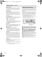
... for both the AV receiver and remote controller (see page 42). d. Remote ID With this preference, you can change this preference, you can manually set the same ID on the display device, when Non-Inter- Digital Input Signal Formats The digital input signal formats are not displayed on the... high by specifying a maximum volume level. Digital signals in the main room. Off: Actions not displayed. However, if you experience either of another Onkyo component located in onscreen setup menus flickers due to Non-Interlaced. Scan Mode If the text in the same room. • If you...
... for both the AV receiver and remote controller (see page 42). d. Remote ID With this preference, you can change this preference, you can manually set the same ID on the display device, when Non-Inter- Digital Input Signal Formats The digital input signal formats are not displayed on the... high by specifying a maximum volume level. Digital signals in the main room. Off: Actions not displayed. However, if you experience either of another Onkyo component located in onscreen setup menus flickers due to Non-Interlaced. Scan Mode If the text in the same room. • If you...

