
English Manual
Page 2
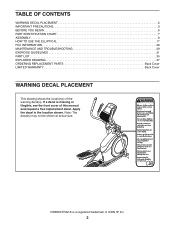
...decal is a registered trademark of ICON IP, Inc. 2 TABLE OF CONTENTS WARNING DECAL PLACEMENT 2 IMPORTANT PRECAUTIONS 3 BEFORE YOU BEGIN 6 PART IDENTIFICATION CHART 7 ASSEMBLY 8 HOW TO USE THE ELLIPTICAL 17 FCC INFORMATION 28 MAINTENANCE AND TROUBLESHOOTING 29 EXERCISE GUIDELINES 31 PART LIST 35 EXPLODED DRAWING 37 ORDERING REPLACEMENT PARTS Back Cover LIMITED...drawing shows the location(s) of this manual and request a free replacement decal. Note: The decal(s) may not be shown at actual size. NORDICTRACK is missing or illegible, see the front cover of the warning decal(s).
...decal is a registered trademark of ICON IP, Inc. 2 TABLE OF CONTENTS WARNING DECAL PLACEMENT 2 IMPORTANT PRECAUTIONS 3 BEFORE YOU BEGIN 6 PART IDENTIFICATION CHART 7 ASSEMBLY 8 HOW TO USE THE ELLIPTICAL 17 FCC INFORMATION 28 MAINTENANCE AND TROUBLESHOOTING 29 EXERCISE GUIDELINES 31 PART LIST 35 EXPLODED DRAWING 37 ORDERING REPLACEMENT PARTS Back Cover LIMITED...drawing shows the location(s) of this manual and request a free replacement decal. Note: The decal(s) may not be shown at actual size. NORDICTRACK is missing or illegible, see the front cover of the warning decal(s).

English Manual
Page 7
Extra parts may be included. PART IDENTIFICATION CHART Use the drawings below each drawing is the quantity needed for assembly. The number following the key number is the key number of the part, from the PART LIST near the end of this manual. M5 Washer (...)–-4 M10 x 25mm Screw (99)–-4 M10 x 122mm Screw (104)–-4 7 The number in the hardware kit, check to identify the small parts needed for assembly. Note: If a part is not in parentheses below to see if it has been preassembled.
Extra parts may be included. PART IDENTIFICATION CHART Use the drawings below each drawing is the quantity needed for assembly. The number following the key number is the key number of the part, from the PART LIST near the end of this manual. M5 Washer (...)–-4 M10 x 25mm Screw (99)–-4 M10 x 122mm Screw (104)–-4 7 The number in the hardware kit, check to identify the small parts needed for assembly. Note: If a part is not in parentheses below to see if it has been preassembled.
English Manual
Page 8
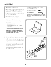
... the second person hold the Frame to the Frame (1) with two M10 x 122mm Screws (104) and two M10 Split Washers (105). ASSEMBLY •• Assembly requires two persons. •• Place all assembly steps. •• Left parts are marked “"L”" or “"Left”" and right parts are marked “"R”... of the Frame (1). To avoid damaging parts, do not have Internet access, call CUSTOMER CARE (see page 7. •• In addition to the included tool(s), assembly requires the following tools: one Phillips screwdriver one rubber mallet...
... the second person hold the Frame to the Frame (1) with two M10 x 122mm Screws (104) and two M10 Split Washers (105). ASSEMBLY •• Assembly requires two persons. •• Place all assembly steps. •• Left parts are marked “"L”" or “"Left”" and right parts are marked “"R”... of the Frame (1). To avoid damaging parts, do not have Internet access, call CUSTOMER CARE (see page 7. •• In addition to the included tool(s), assembly requires the following tools: one Phillips screwdriver one rubber mallet...

English Manual
Page 30
Next, see assembly step 15 on page 37. See EXPLODED DRAWING C on page 39 and EXPLODED DRAWING A on page 15 and remove the Right Upper Body Leg Outer and Inner Covers (69, 83). Remove the M4 x 19mm Screws (5) and the M4 x 48mm Screw (107) from the elliptical. 89 91 Reattach the right ...shield, the right roller arm, the right pedal arm, the shield cover cap, and the shield cover. 30 Then, carefully remove the Right Roller Arm assembly from the Left and Right Shields (73, 74). Use a flat...
Next, see assembly step 15 on page 37. See EXPLODED DRAWING C on page 39 and EXPLODED DRAWING A on page 15 and remove the Right Upper Body Leg Outer and Inner Covers (69, 83). Remove the M4 x 19mm Screws (5) and the M4 x 48mm Screw (107) from the elliptical. 89 91 Reattach the right ...shield, the right roller arm, the right pedal arm, the shield cover cap, and the shield cover. 30 Then, carefully remove the Right Roller Arm assembly from the Left and Right Shields (73, 74). Use a flat...

English Manual
Page 35
... Washer Small Axle Cover Roller Arm Bushing Arm Bearing Right Pedal Arm Right Roller Arm Right Upper Body Leg Right Upper Body Arm Grip Sensor Assembly/Wire Pedal Arm Axle Right Upper Body Arm Front Cover Right Upper Body Arm Rear Cover Left Upper Body Arm Front Cover Left Upper Body...
... Washer Small Axle Cover Roller Arm Bushing Arm Bearing Right Pedal Arm Right Roller Arm Right Upper Body Leg Right Upper Body Arm Grip Sensor Assembly/Wire Pedal Arm Axle Right Upper Body Arm Front Cover Right Upper Body Arm Rear Cover Left Upper Body Arm Front Cover Left Upper Body...

English Manual
Page 36
... Cover Cap Power Cord Ramp Axle Small Frame Bushing Clevis Pin Plastic Spacer M4 x 19mm Self-tapping Screw Bumper Right Pedal Pedal Insert Extension Wire Assembly Tool Grease Packet User’'s Manual Note: Specifications are not illustrated. 36 Description 101 35 102 10 103 8 104 4 105 8 106 3 107 1 108 2 109 2 110...
... Cover Cap Power Cord Ramp Axle Small Frame Bushing Clevis Pin Plastic Spacer M4 x 19mm Self-tapping Screw Bumper Right Pedal Pedal Insert Extension Wire Assembly Tool Grease Packet User’'s Manual Note: Specifications are not illustrated. 36 Description 101 35 102 10 103 8 104 4 105 8 106 3 107 1 108 2 109 2 110...


