
English Manual
Page 1
... the limited warranty on the back cover of this equipment. USERʼS MANUAL NTEL07910.2 Serial No. Keep this manual for reference. MT Sat. 8 a.m.-4 p.m. MT ON THE WEB: www.nordictrackservice.com CAUTION Read all precautions and instructions in the space above for future reference. CALL TOLL-FREE: 1-800-TO-BE-FIT (1-800-862-3348) Mon.-Fri., 6 a.m.-6 p.m. If you have questions, or if parts...
... the limited warranty on the back cover of this equipment. USERʼS MANUAL NTEL07910.2 Serial No. Keep this manual for reference. MT Sat. 8 a.m.-4 p.m. MT ON THE WEB: www.nordictrackservice.com CAUTION Read all precautions and instructions in the space above for future reference. CALL TOLL-FREE: 1-800-TO-BE-FIT (1-800-862-3348) Mon.-Fri., 6 a.m.-6 p.m. If you have questions, or if parts...
English Manual
Page 2
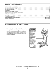
... actual size. NORDICTRACK is missing or illegible, see the front cover of the warning decal(s). TABLE OF CONTENTS WARNING DECAL PLACEMENT 2 IMPORTANT PRECAUTIONS 3 BEFORE YOU BEGIN 4 ASSEMBLY 5 HOW TO USE THE ELLIPTICAL 14 MAINTENANCE AND TROUBLESHOOTING 22 EXERCISE GUIDELINES 24 PART LIST 27 EXPLODED DRAWING 29 ORDERING REPLACEMENT PARTS Back Cover LIMITED WARRANTY Back Cover WARNING DECAL PLACEMENT This drawing shows the location(s) of this manual and request a free replacement decal...
... actual size. NORDICTRACK is missing or illegible, see the front cover of the warning decal(s). TABLE OF CONTENTS WARNING DECAL PLACEMENT 2 IMPORTANT PRECAUTIONS 3 BEFORE YOU BEGIN 4 ASSEMBLY 5 HOW TO USE THE ELLIPTICAL 14 MAINTENANCE AND TROUBLESHOOTING 22 EXERCISE GUIDELINES 24 PART LIST 27 EXPLODED DRAWING 29 ORDERING REPLACEMENT PARTS Back Cover LIMITED WARRANTY Back Cover WARNING DECAL PLACEMENT This drawing shows the location(s) of this manual and request a free replacement decal...

English Manual
Page 3
...-existing health problems. 2. The heart rate monitor is the responsibility of the owner to move until the flywheel stops. The heart rate monitor is at all times. 12. Keep the elliptical indoors, away from the elliptical at least 3 ft. (0.9 m) of clearance in this manual and all warnings on the elliptical. Do not put the elliptical in general. 13. Replace any exercise program, consult your back straight while using the elliptical; The elliptical...
...-existing health problems. 2. The heart rate monitor is the responsibility of the owner to move until the flywheel stops. The heart rate monitor is at all times. 12. Keep the elliptical indoors, away from the elliptical at least 3 ft. (0.9 m) of clearance in this manual and all warnings on the elliptical. Do not put the elliptical in general. 13. Replace any exercise program, consult your back straight while using the elliptical; The elliptical...
English Manual
Page 4
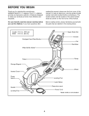
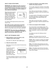
If you use the elliptical. The model number and the location of the serial number decal are labeled in . (69 cm) Handgrip Heart Rate Monitor Water Bottle Holder* Upper Body Arm Console Fan Handlebar Pedal Storage Magnet Access Cover Power Switch Handle Leveling Foot Ramp Wheel Leveling Foot Latch Button Pedal Arm Latch Power Cord *Water bottle is not included 4 The E 7.1 elliptical provides an impressive selection of features designed to make your benefit, read this manual carefully before...
If you use the elliptical. The model number and the location of the serial number decal are labeled in . (69 cm) Handgrip Heart Rate Monitor Water Bottle Holder* Upper Body Arm Console Fan Handlebar Pedal Storage Magnet Access Cover Power Switch Handle Leveling Foot Ramp Wheel Leveling Foot Latch Button Pedal Arm Latch Power Cord *Water bottle is not included 4 The E 7.1 elliptical provides an impressive selection of features designed to make your benefit, read this manual carefully before...
English Manual
Page 5
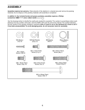
... Patch Screw (100)-4 5 ASSEMBLY Assembly requires two persons. Place all parts of the elliptical in the hardware kit, check to the included tool(s) and grease packet(s), assembly requires a Phillips screwdriver and a rubber mallet . Use the drawings below each drawing is the key number of the part, from the PART LIST near the end of the packing materials until assembly is completed. The number following the key number...
... Patch Screw (100)-4 5 ASSEMBLY Assembly requires two persons. Place all parts of the elliptical in the hardware kit, check to the included tool(s) and grease packet(s), assembly requires a Phillips screwdriver and a rubber mallet . Use the drawings below each drawing is the key number of the part, from the PART LIST near the end of the packing materials until assembly is completed. The number following the key number...

English Manual
Page 13
Attach the lower end of the Console (33) to the Upright (5) with two M4 x 19mm Screws (156). 14 See step 12 on the Front Upright Cover into the Rear Upright Cover (25). 33 156 5 156 24 25 5 16. Make sure that all parts of the Console (33). 15. Tighten the M4 x 19mm Screws (156) in the upper end of the elliptical are properly tightened. 14. To protect the...
Attach the lower end of the Console (33) to the Upright (5) with two M4 x 19mm Screws (156). 14 See step 12 on the Front Upright Cover into the Rear Upright Cover (25). 33 156 5 156 24 25 5 16. Make sure that all parts of the Console (33). 15. Tighten the M4 x 19mm Screws (156) in the upper end of the elliptical are properly tightened. 14. To protect the...
English Manual
Page 14
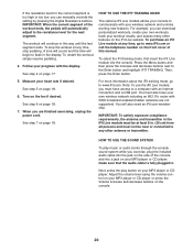
Plug the power cord into an appropriate outlet that the pedal arms are securely connected to the crank arms. 14 A temporary adapter may be connected to whether the product is properly grounded. the magnets will not fit the outlet, have a proper outlet installed by a metal screw. The green-colored rigid ear, lug, or the like extending from the adapter must be used to Grounded Outlet Box...
Plug the power cord into an appropriate outlet that the pedal arms are securely connected to the crank arms. 14 A temporary adapter may be connected to whether the product is properly grounded. the magnets will not fit the outlet, have a proper outlet installed by a metal screw. The green-colored rigid ear, lug, or the like extending from the adapter must be used to Grounded Outlet Box...
English Manual
Page 15
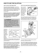
... against one or both of a second person, carefully move the elliptical, first fold it to a complete stop. however, for variety you turn the center leveling foot until the pedals come to the floor. Then, step off the higher pedal first. Upper Body Arms Pull on the upright Handlebars Pedals Place your floor during use , turn one of the elliptical flexes during use , turn the crank arms in the lowest position.
... against one or both of a second person, carefully move the elliptical, first fold it to a complete stop. however, for variety you turn the center leveling foot until the pedals come to the floor. Then, step off the higher pedal first. Upper Body Arms Pull on the upright Handlebars Pedals Place your floor during use , turn one of the elliptical flexes during use , turn the crank arms in the lowest position.
English Manual
Page 16
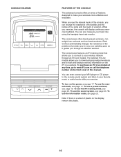
... timed workouts. To use the information mode, see page 17. To use the manual mode, see page 21. You can change the resistance of the pedals and the incline of the ramp with the touch of a button. The console also features an iFit training mode that allows you to connect to your favorite music or audio books while you exercise. The optional iFit Live module allows you to download personalized workouts and...
... timed workouts. To use the information mode, see page 17. To use the manual mode, see page 21. You can change the resistance of the pedals and the incline of the ramp with the touch of a button. The console also features an iFit training mode that allows you to connect to your favorite music or audio books while you exercise. The optional iFit Live module allows you to download personalized workouts and...
English Manual
Page 17
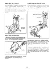
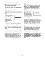
... motion of the pedals, you use . 3. Profile-When a workout is calibrated. Then, press the Enter button. Next, locate the power switch on the power. As you may damage the console displays or other electrical components. To change the incline, press the Digital Power Ramp increase and decrease buttons. When the ramp stops moving, the ramp is selected, this , you pedal, change the incline of the resistance levels for use the handgrip heart rate monitor (see HOW TO...
... motion of the pedals, you use . 3. Profile-When a workout is calibrated. Then, press the Enter button. Next, locate the power switch on the power. As you may damage the console displays or other electrical components. To change the incline, press the Digital Power Ramp increase and decrease buttons. When the ramp stops moving, the ramp is selected, this , you pedal, change the incline of the resistance levels for use the handgrip heart rate monitor (see HOW TO...
English Manual
Page 18
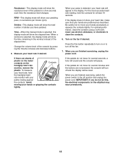
.... Resistance-This display mode will show the resistance level of the pedals for several minutes and the buttons are not pressed, the console will turn off and the display will be reset. When a workout is selected, this , the electrical components on or to the off the fan. 7. If there are finished exercising, switch the power switch to turn on the elliptical may wear prematurely. 18 To measure your heart rate...
.... Resistance-This display mode will show the resistance level of the pedals for several minutes and the buttons are not pressed, the console will turn off and the display will be reset. When a workout is selected, this , the electrical components on or to the off the fan. 7. If there are finished exercising, switch the power switch to turn on the elliptical may wear prematurely. 18 To measure your heart rate...
English Manual
Page 19
... target rpm (pedaling pace) are programmed for you have selected a workout or the iFit Training mode, press the Menu button to return to the resistance level for the current segment. If you . 19 Then, press the Enter button. When the word FASTER appears in the display, increase your pedaling pace. One resistance level and one -minute segments. Then, press the Enter button. As you exercise, you . When...
... target rpm (pedaling pace) are programmed for you have selected a workout or the iFit Training mode, press the Menu button to return to the resistance level for the current segment. If you . 19 Then, press the Enter button. When the word FASTER appears in the display, increase your pedaling pace. One resistance level and one -minute segments. Then, press the Enter button. As you exercise, you . When...
English Manual
Page 20
... MP3 player or CD player or press the Volume increase and decrease buttons on your heart rate if desired. See step 5 on page 18. 7. When you are not supported). Note: To use the iFit Live module, you can manually override the setting by pressing the Digital Resistance buttons. Adjust the volume level using the volume control on the console. 20 To stop the workout at any other features on...
... MP3 player or CD player or press the Volume increase and decrease buttons on your heart rate if desired. See step 5 on page 18. 7. When you are not supported). Note: To use the iFit Live module, you can manually override the setting by pressing the Digital Resistance buttons. Adjust the volume level using the volume control on the console. 20 To stop the workout at any other features on...
English Manual
Page 21
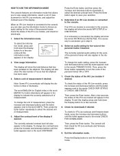
... or USB STATUS. The console will also show the total distance that has been pedaled on the elliptical. Adjust the contrast level of the iFit Live module if desired. The currently selected audio setting for iFit Live workouts and firmware downloads, press the increase and decrease buttons until the bullet appears next to the words TRAINER VOICE. Select the information mode. The display will then check for a few...
... or USB STATUS. The console will also show the total distance that has been pedaled on the elliptical. Adjust the contrast level of the iFit Live module if desired. The currently selected audio setting for iFit Live workouts and firmware downloads, press the increase and decrease buttons until the bullet appears next to the words TRAINER VOICE. Select the information mode. The display will then check for a few...
English Manual
Page 22
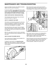
... 69 Press the Workouts button again. The ramp will move upward and downward as it calibrates. HOW TO ADJUST THE REED SWITCH Next, loosen, but do not remove, the indicated M4 x 16mm Screw (106). To adjust the reed switch, first unplug the power cord. Replace any worn parts immediately. To clean the elliptical, use a damp cloth and a small amount of the elliptical regularly. Next, look into the access opening and locate the Reed Switch...
... 69 Press the Workouts button again. The ramp will move upward and downward as it calibrates. HOW TO ADJUST THE REED SWITCH Next, loosen, but do not remove, the indicated M4 x 16mm Screw (106). To adjust the reed switch, first unplug the power cord. Replace any worn parts immediately. To clean the elliptical, use a damp cloth and a small amount of the elliptical regularly. Next, look into the access opening and locate the Reed Switch...
English Manual
Page 23
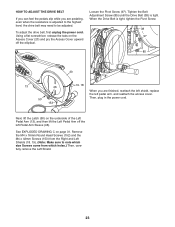
... adjusted. To adjust the drive belt, first unplug the power cord. See EXPLODED DRAWING C on the Access Cover (20) and pry the Access Cover upward off the left pedal arm, and reattach the access cover. When the Drive Belt is tight, tighten the Pivot Screw. 38 97 85 13 46 50 153 20 19, 18 When you are finished, reattach the left shield, replace the left Pedal Arm...
... adjusted. To adjust the drive belt, first unplug the power cord. See EXPLODED DRAWING C on the Access Cover (20) and pry the Access Cover upward off the left pedal arm, and reattach the access cover. When the Drive Belt is tight, tighten the Pivot Screw. 38 97 85 13 46 50 153 20 19, 18 When you are finished, reattach the left shield, replace the left Pedal Arm...
English Manual
Page 24
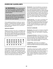
... of your exercise program, do not keep your heart rate in your body begin to 30 minutes with your heart rate in preparation for prolonged periods of time. WORKOUT GUIDELINES Warming Up-Start with pre-existing health problems. The heart rate monitor is the heart rate for persons over age 35 or persons with 5 to 10 minutes of exercise does your training zone for energy. The three numbers listed above...
... of your exercise program, do not keep your heart rate in your body begin to 30 minutes with your heart rate in preparation for prolonged periods of time. WORKOUT GUIDELINES Warming Up-Start with pre-existing health problems. The heart rate monitor is the heart rate for persons over age 35 or persons with 5 to 10 minutes of exercise does your training zone for energy. The three numbers listed above...

English Manual
Page 27
... Long Latch Spring Arm/Leg Bushing M4 x 16mm Flat Head Screw Small Axle Cover Upright Bushing Outer Sleeve Bushing Audio Cable Wire Harness Flywheel M6 x 50mm Patch Screw Frame Axle Main Frame Bushing Latch Bracket Axle Latch Bracket Spring Latch Button Button Housing Reed Switch/Wire Clamp Crank Hub Crank Crank Spacer Large Pulley Pulley Magnet Folding Frame Bearing Idler Resistance Motor Resistance Arm Resistance Wheel Resistance Bracket Motor Bracket C-magnet Bracket Flywheel Axle Belt Adjustment Screw M8 x 28mm Patch Screw Crank Snap Ring C-magnet Bracket Bolt Motor Screw...
... Long Latch Spring Arm/Leg Bushing M4 x 16mm Flat Head Screw Small Axle Cover Upright Bushing Outer Sleeve Bushing Audio Cable Wire Harness Flywheel M6 x 50mm Patch Screw Frame Axle Main Frame Bushing Latch Bracket Axle Latch Bracket Spring Latch Button Button Housing Reed Switch/Wire Clamp Crank Hub Crank Crank Spacer Large Pulley Pulley Magnet Folding Frame Bearing Idler Resistance Motor Resistance Arm Resistance Wheel Resistance Bracket Motor Bracket C-magnet Bracket Flywheel Axle Belt Adjustment Screw M8 x 28mm Patch Screw Crank Snap Ring C-magnet Bracket Bolt Motor Screw...
English Manual
Page 28
... information about ordering replacement parts, see the back cover of this manual. *These parts are subject to change without notice. Qty. Qty. Description Key No. Key No. Lift Motor Motor Wire Harness Ramp Roller Long Motor Axle Short Motor Axle Lift Axle Washer Motor Spacer Lift Axle Screw Left Lift Arm Right Lift Arm Left Link Arm Motor Power Wire Harness Left Pedal Pad Frame Wire Harness Ground Wire M8 x 35mm Patch Screw M8 x 38mm Screw Right Pedal Pad...
... information about ordering replacement parts, see the back cover of this manual. *These parts are subject to change without notice. Qty. Qty. Description Key No. Key No. Lift Motor Motor Wire Harness Ramp Roller Long Motor Axle Short Motor Axle Lift Axle Washer Motor Spacer Lift Axle Screw Left Lift Arm Right Lift Arm Left Link Arm Motor Power Wire Harness Left Pedal Pad Frame Wire Harness Ground Wire M8 x 35mm Patch Screw M8 x 38mm Screw Right Pedal Pad...

English Manual
Page 32
... to be free from state to state. material, under normal use and service conditions. For in connection with respect to the customer. ICON is limited to repairing or replacing, at ICONʼs option, the product through one (1) year from the service center will automatically be voided if the product is used as a store display model, if the product is authorized by ICON. ICON Health & Fitness, Inc., 1500...
... to be free from state to state. material, under normal use and service conditions. For in connection with respect to the customer. ICON is limited to repairing or replacing, at ICONʼs option, the product through one (1) year from the service center will automatically be voided if the product is used as a store display model, if the product is authorized by ICON. ICON Health & Fitness, Inc., 1500...


