
User Manual
Page 2
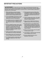
... 3 BEFORE YOU BEGIN 4 ASSEMBLY 5 HOW TO USE THE ELLIPTICAL EXERCISER 12 MAINTENANCE AND TROUBLESHOOTING 20 EXERCISE GUIDELINES 21 PART LIST 24 EXPLODED DRAWING 26 ORDERING REPLACEMENT PARTS Back Cover LIMITED WARRANTY Back Cover WARNING DECAL PLACEMENT The warning decals shown here have been applied in the location shown. Apply the decal in the locations shown. Note: The decal may not be shown at actual size. If a decal is...
... 3 BEFORE YOU BEGIN 4 ASSEMBLY 5 HOW TO USE THE ELLIPTICAL EXERCISER 12 MAINTENANCE AND TROUBLESHOOTING 20 EXERCISE GUIDELINES 21 PART LIST 24 EXPLODED DRAWING 26 ORDERING REPLACEMENT PARTS Back Cover LIMITED WARRANTY Back Cover WARNING DECAL PLACEMENT The warning decals shown here have been applied in the location shown. Apply the decal in the locations shown. Note: The decal may not be shown at actual size. If a decal is...
User Manual
Page 3
... caught on your elliptical exerciser before using your elliptical exerciser. Replace any exercise program, consult your elliptical exerciser in this manual and all warnings on your elliptical exerciser; Your elliptical exerciser should not be used by or through the use only. The pulse sensor is intended for persons over the age of heart rate readings. When you feel pain or dizziness while exercising, stop . 13. Before beginning any worn parts immediately. 6. The pulse sensor is enough...
... caught on your elliptical exerciser before using your elliptical exerciser. Replace any exercise program, consult your elliptical exerciser in this manual and all warnings on your elliptical exerciser; Your elliptical exerciser should not be used by or through the use only. The pulse sensor is intended for persons over the age of heart rate readings. When you feel pain or dizziness while exercising, stop . 13. Before beginning any worn parts immediately. 6. The pulse sensor is enough...
User Manual
Page 4
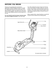
Upper Body Arm Fan Console Pulse Sensor Water Bottle Holder* Pedal Disc Handle Wheel Pedal Latch Button *No water bottle is included 4 To help us . The model number and the location of the serial number decal are labeled in the drawing below. For your workouts at home more effective and enjoyable-and when you for purchasing the revolutionary NordicTrack® ASR 630 elliptical exerciser. The ASR 630 elliptical exerciser provides a wide array of features designed to...
Upper Body Arm Fan Console Pulse Sensor Water Bottle Holder* Pedal Disc Handle Wheel Pedal Latch Button *No water bottle is included 4 To help us . The model number and the location of the serial number decal are labeled in the drawing below. For your workouts at home more effective and enjoyable-and when you for purchasing the revolutionary NordicTrack® ASR 630 elliptical exerciser. The ASR 630 elliptical exerciser provides a wide array of features designed to...
User Manual
Page 5
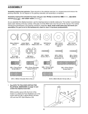
... all parts of this manual. See HOW TO FOLD AND UNFOLD THE ELLIPTICAL EXERCISER on page 12 and 1 unfold the elliptical exerciser. While another person lifts the front of the packing materials until assembly is the key number of the part, from the PART LIST near the end of the elliptical exerciser in parentheses below to identify small parts. The number in a cleared area and remove the packing materials. The number...
... all parts of this manual. See HOW TO FOLD AND UNFOLD THE ELLIPTICAL EXERCISER on page 12 and 1 unfold the elliptical exerciser. While another person lifts the front of the packing materials until assembly is the key number of the part, from the PART LIST near the end of the elliptical exerciser in parentheses below to identify small parts. The number in a cleared area and remove the packing materials. The number...

User Manual
Page 7
... Upright (10) near the Frame (1), connect the Upper Wire Harness (65) to pinch the Wire Harnesses (64, 65) during this step. Orient the Left and Right Upright Covers (19, 20) as shown. Then, insert the Upright (10) into the Frame (1). Tip: Be careful not to the Lower Wire Harness (64). Then, attach the Upright Covers 5 around the Upright (10) with four M8 x 19mm Patch Screws...
... Upright (10) near the Frame (1), connect the Upper Wire Harness (65) to pinch the Wire Harnesses (64, 65) during this step. Orient the Left and Right Upright Covers (19, 20) as shown. Then, insert the Upright (10) into the Frame (1). Tip: Be careful not to the Lower Wire Harness (64). Then, attach the Upright Covers 5 around the Upright (10) with four M8 x 19mm Patch Screws...
User Manual
Page 9
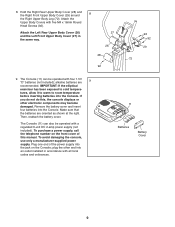
... Screws (92). Remove the battery cover and insert four batteries into the jack on the Console; Hold the Right Rear Upper Body Cover (28) and the Right Front Upper Body Cover (29) around 8 the Right Upper Body Leg (72). Plug one end of this , the console displays or other end into the Console. 8. To purchase a power supply, call the telephone number on the front cover of the power supply into the Console...
... Screws (92). Remove the battery cover and insert four batteries into the jack on the Console; Hold the Right Rear Upper Body Cover (28) and the Right Front Upper Body Cover (29) around 8 the Right Upper Body Leg (72). Plug one end of this , the console displays or other end into the Console. 8. To purchase a power supply, call the telephone number on the front cover of the power supply into the Console...

User Manual
Page 10
...). Repeat this step 11. 10. Attach the Right Pedal to the Upright (10) with 11 four M4 x 16mm Screws (78). 65 78 Console Wire Harness 78 Avoid pinching the wire harnesses during this step. 10 While another person holds the Console (11) near the Upright (10), connect the console wire harness to the Upper Wire Harness (65). 10 Attach the Console (11) to the Link Arm 35 with...
...). Repeat this step 11. 10. Attach the Right Pedal to the Upright (10) with 11 four M4 x 16mm Screws (78). 65 78 Console Wire Harness 78 Avoid pinching the wire harnesses during this step. 10 While another person holds the Console (11) near the Upright (10), connect the console wire harness to the Upper Wire Harness (65). 10 Attach the Console (11) to the Link Arm 35 with...
User Manual
Page 11
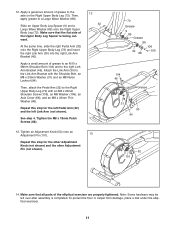
... Right Upper Body Leg (72) and insert the right Link Arm (30) into the right Link Arm Bracket (45). Repeat this step for the left Pedal Arm (32) and the left over after assembly is facing outward. Tighten an Adjustment Knob (52) onto an Adjustment Pin (101). 13 Repeat this step for the other Adjustment Knob (not shown) and the other Adjustment Pin (not shown). 72 Grease 9 89 Grease 96...
... Right Upper Body Leg (72) and insert the right Link Arm (30) into the right Link Arm Bracket (45). Repeat this step for the left Pedal Arm (32) and the left over after assembly is facing outward. Tighten an Adjustment Knob (52) onto an Adjustment Pin (101). 13 Repeat this step for the other Adjustment Knob (not shown) and the other Adjustment Pin (not shown). 72 Grease 9 89 Grease 96...
User Manual
Page 12
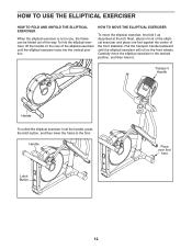
... Latch Button Place your foot here 12 To fold the elliptical exerciser, lift the handle on the front wheels. Next, stand in use, the frame can be folded out of the way. Pull the transport handle backward until the elliptical exerciser will roll on the rear of the elliptical exerciser until the elliptical exerciser locks into the vertical position. HOW TO MOVE THE ELLIPTICAL EXERCISER To move the elliptical exerciser...
... Latch Button Place your foot here 12 To fold the elliptical exerciser, lift the handle on the front wheels. Next, stand in use, the frame can be folded out of the way. Pull the transport handle backward until the elliptical exerciser will roll on the rear of the elliptical exerciser until the elliptical exerciser locks into the vertical position. HOW TO MOVE THE ELLIPTICAL EXERCISER To move the elliptical exerciser...
User Manual
Page 14
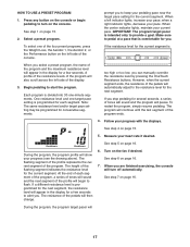
... preset programs. Each program automatically changes the resistance of the console, follow the steps beginning on the front cover of a personal trainer coaches you and motivates you through an effective workout. For example, lose unwanted pounds with iFIT Cards containing workout programs designed to help you achieve specific fitness goals. To use the manual mode of the pedals and prompts you to increase or decrease your pedaling pace as it guides...
... preset programs. Each program automatically changes the resistance of the console, follow the steps beginning on the front cover of a personal trainer coaches you and motivates you through an effective workout. For example, lose unwanted pounds with iFIT Cards containing workout programs designed to help you achieve specific fitness goals. To use the manual mode of the pedals and prompts you to increase or decrease your pedaling pace as it guides...
User Manual
Page 15
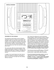
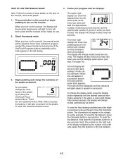
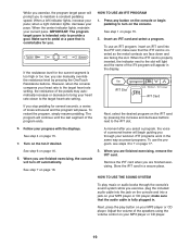
... pedal, change the display mode, press the Display button repeatedly until the desired exercise information appears in the upper or lower right display. Begin pedaling and change modes every few seconds. As you have selected a program, reselect the manual mode by pressing the OneTouch Resistance buttons. The display will also show a track representing 1/4 mile. The left display will appear in the left side equals the total distance or the trip distance. 15 The information will show your heart rate...
... pedal, change the display mode, press the Display button repeatedly until the desired exercise information appears in the upper or lower right display. Begin pedaling and change modes every few seconds. As you have selected a program, reselect the manual mode by pressing the OneTouch Resistance buttons. The display will also show a track representing 1/4 mile. The left display will appear in the left side equals the total distance or the trip distance. 15 The information will show your heart rate...
User Manual
Page 16
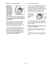
... at high speed, press the Fan button. To select the auto mode, press the Fan button a third time; Pivot the thumb tab on the handgrip pulse sensor, remove the plas- When you increase or decrease your hands excessively or to squeeze the metal contacts tightly. If the pedals do not move for about five minutes, the console will turn off to move for about...
... at high speed, press the Fan button. To select the auto mode, press the Fan button a third time; Pivot the thumb tab on the handgrip pulse sensor, remove the plas- When you increase or decrease your hands excessively or to squeeze the metal contacts tightly. If the pedals do not move for about five minutes, the console will turn off to move for about...
User Manual
Page 17
... you . Note: The same resistance level and/or target pace setting may be programmed for the next segment. If you are finished exercising, the console will automatically adjust to start the program. Measure your progress with the displays. The height of the four preset programs, press the Weight Loss, the Aerobic 1, the Aerobic 2, or the Performance button on the console. At the end of...
... you . Note: The same resistance level and/or target pace setting may be programmed for the next segment. If you are finished exercising, the console will automatically adjust to start the program. Measure your progress with the displays. The height of the four preset programs, press the Weight Loss, the Aerobic 1, the Aerobic 2, or the Performance button on the console. At the end of...
User Manual
Page 18
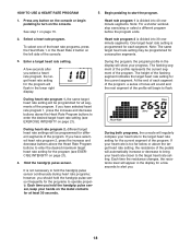
... heart rate settings will be programmed for the current segment. Hold the handgrip pulse sensor. HOW TO USE A HEART RATE PROGRAM 5. The flashing segment of the profile represents the current segment of the flashing segment indicates the target heart rate setting for consecutive segments. 3. At the end of the console. Each time you select a heart rate program, the target heart rate setting for different segments of the program. Note: For a shorter workout, stop exercising...
... heart rate settings will be programmed for the current segment. Hold the handgrip pulse sensor. HOW TO USE A HEART RATE PROGRAM 5. The flashing segment of the profile represents the current segment of the flashing segment indicates the target heart rate setting for consecutive segments. 3. At the end of the console. Each time you select a heart rate program, the target heart rate setting for different segments of the program. Note: For a shorter workout, stop exercising...
User Manual
Page 19
... your pace; Press any button on the console or begin guiding you . To use the program, see steps 3 to turn off automatically. See step 4 on the console. A moment after you are finished exercising, the console will begin pedaling to 7 on page 16. 3. See step 6 on the iFIT card by pressing the OneTouch Resistance buttons. IMPORTANT: The program target pacer is fully plugged in the display. make sure that the audio cable is intended only...
... your pace; Press any button on the console or begin guiding you . To use the program, see steps 3 to turn off automatically. See step 4 on the console. A moment after you are finished exercising, the console will begin pedaling to 7 on page 16. 3. See step 6 on the iFIT card by pressing the OneTouch Resistance buttons. IMPORTANT: The program target pacer is fully plugged in the display. make sure that the audio cable is intended only...
User Manual
Page 20
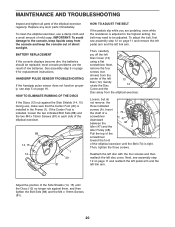
... PULSE SENSOR TROUBLESHOOTING If the handgrip pulse sensor does not function properly, see step 5 on page 9 for replacement instructions. most console problems are pedaling, even while the resistance is adjusted to the highest setting, the belt may need to the console, keep the console out of direct sunlight. To clean the elliptical exerciser, use , make sure that the Center Foot (40) is tight. See assembly step 9 on page 16. If the Center Foot is installed...
... PULSE SENSOR TROUBLESHOOTING If the handgrip pulse sensor does not function properly, see step 5 on page 9 for replacement instructions. most console problems are pedaling, even while the resistance is adjusted to the highest setting, the belt may need to the console, keep the console out of direct sunlight. To clean the elliptical exerciser, use , make sure that the Center Foot (40) is tight. See assembly step 9 on page 16. If the Center Foot is installed...
User Manual
Page 21
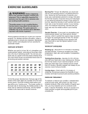
... stretching and light exercise. After a few weeks of your exercise until your cardiovascular system, you to five workouts each week, with your heart rate near the highest number in your training zone. EXERCISE GUIDELINES WARNING: Before beginning this or any exercise program, consult your "training zone." The pulse sensor is the key to strengthen your cardiovascular system, exercising at the bottom of the chart (ages are...
... stretching and light exercise. After a few weeks of your exercise until your cardiovascular system, you to five workouts each week, with your heart rate near the highest number in your training zone. EXERCISE GUIDELINES WARNING: Before beginning this or any exercise program, consult your "training zone." The pulse sensor is the key to strengthen your cardiovascular system, exercising at the bottom of the chart (ages are...
User Manual
Page 24
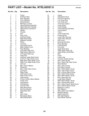
... Description Clamp Adjustment Knob Pivot Arm Bushing Link Snap Ring Left Crank Arm Crank Arm Spacer Large Pulley Crank Flange Crank Bearing Assembly Crank Spacer Crank Crank Snap Ring Flange Screw Lower Wire Harness Upper Wire Harness Axle Cover Bushing Assembly Brass Bushing Latch Bracket Pivot Axle Upper Body Axle Right Upper Body Leg Upper Body Leg Endcap Belt Foam Frame Cap Transfer Handle Endcap M4 x 16mm Screw M4 x 16mm Flat Head Screw Wave Washer M4 x 19mm Screw M10 Nylon...
... Description Clamp Adjustment Knob Pivot Arm Bushing Link Snap Ring Left Crank Arm Crank Arm Spacer Large Pulley Crank Flange Crank Bearing Assembly Crank Spacer Crank Crank Snap Ring Flange Screw Lower Wire Harness Upper Wire Harness Axle Cover Bushing Assembly Brass Bushing Latch Bracket Pivot Axle Upper Body Axle Right Upper Body Leg Upper Body Leg Endcap Belt Foam Frame Cap Transfer Handle Endcap M4 x 16mm Screw M4 x 16mm Flat Head Screw Wave Washer M4 x 19mm Screw M10 Nylon...

User Manual
Page 25
Description Key No. See the back cover of this manual for information about ordering replacement parts. *These parts are subject to change without notice. Key No. M8 x 32mm Washer Audio Wire Userʼs Manual Hex Key Grease Packet Note: Specifications are not illustrated. 25 Description 101 2 102 2 103 4 104 2 105 2 106 2 Adjustment Pin Adjustment Spacer Large Snap Ring M10 x 58mm Shoulder Bolt M8 x 23mm Shoulder Screw M8 Washer 107 2 * - * - * - * - Qty. Qty.
Description Key No. See the back cover of this manual for information about ordering replacement parts. *These parts are subject to change without notice. Key No. M8 x 32mm Washer Audio Wire Userʼs Manual Hex Key Grease Packet Note: Specifications are not illustrated. 25 Description 101 2 102 2 103 4 104 2 105 2 106 2 Adjustment Pin Adjustment Spacer Large Snap Ring M10 x 58mm Shoulder Bolt M8 x 23mm Shoulder Screw M8 Washer 107 2 * - * - * - * - Qty. Qty.
User Manual
Page 28
... of or in connection with the use , costs of removal or installation or other rights which warranty claims are made must be pre-authorized by an ICON authorized service center; No other warranty beyond that specifically set forth herein. products used as store display models. ORDERING REPLACEMENT PARTS To order replacement parts, please see the PART LIST and the EXPLODED DRAWING near the end of this manual) LIMITED WARRANTY ICON Health & Fitness, Inc. (ICON) warrants this...
... of or in connection with the use , costs of removal or installation or other rights which warranty claims are made must be pre-authorized by an ICON authorized service center; No other warranty beyond that specifically set forth herein. products used as store display models. ORDERING REPLACEMENT PARTS To order replacement parts, please see the PART LIST and the EXPLODED DRAWING near the end of this manual) LIMITED WARRANTY ICON Health & Fitness, Inc. (ICON) warrants this...


