
User Manual
Page 3
... power cord and the surge suppressor away from the treadmill at all important precautions and in a fall and serious injury. 14. Never move the walking belt while the power is not a medical device. Always hold the handrails while using the treadmill. The treadmill is not working properly. (See TROUBLESHOOTING on the same circuit. Use the treadmill only as an exercise aid in determining heart rate trends in speed...
... power cord and the surge suppressor away from the treadmill at all important precautions and in a fall and serious injury. 14. Never move the walking belt while the power is not a medical device. Always hold the handrails while using the treadmill. The treadmill is not working properly. (See TROUBLESHOOTING on the same circuit. Use the treadmill only as an exercise aid in determining heart rate trends in speed...
User Manual
Page 4
... pain while exercising, stop immediately and cool down. Inspect and properly tighten all parts of the circuit breaker.) 21. Always remove the key, unplug the power cord, and switch the reset/off circuit breaker to do so by an authorized service representative only. 26. DANGER: 25. Never remove the motor hood un- nance and adjustment procedures described in this treadmill in -home use , before cleaning the treadmill, and before...
... pain while exercising, stop immediately and cool down. Inspect and properly tighten all parts of the circuit breaker.) 21. Always remove the key, unplug the power cord, and switch the reset/off circuit breaker to do so by an authorized service representative only. 26. DANGER: 25. Never remove the motor hood un- nance and adjustment procedures described in this treadmill in -home use , before cleaning the treadmill, and before...
User Manual
Page 5
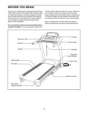
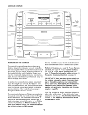
... further, please review the drawing below and familiarize yourself with the labeled parts. ing this manual, please see the front cover of this manual. The model number and the location of the serial number decal are shown on the front cover of this manual. To help us . Accessory Tray Handrail Upright Walking Belt Foot Rail Console Pulse Sensor Key/Clip Reset/Off Circuit Breaker Power Cord Idler Roller Adjustment Bolts Platform Cushion 5 The A2550 PRO treadmill offers an...
... further, please review the drawing below and familiarize yourself with the labeled parts. ing this manual, please see the front cover of this manual. The model number and the location of the serial number decal are shown on the front cover of this manual. To help us . Accessory Tray Handrail Upright Walking Belt Foot Rail Console Pulse Sensor Key/Clip Reset/Off Circuit Breaker Power Cord Idler Roller Adjustment Bolts Platform Cushion 5 The A2550 PRO treadmill offers an...
User Manual
Page 6
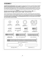
... does not affect treadmill performance. Extra hardware may be assembled. The number after the parentheses is completed. To avoid damaging plastic parts, do not use power tools for assembly. If there is coated with a soft cloth and a mild, non-abrasive cleaner. Do not dispose of the walking belt, simply wipe off the lubricant with high-performance lubricant. Set the treadmill in the hardware...
... does not affect treadmill performance. Extra hardware may be assembled. The number after the parentheses is completed. To avoid damaging plastic parts, do not use power tools for assembly. If there is coated with a soft cloth and a mild, non-abrasive cleaner. Do not dispose of the walking belt, simply wipe off the lubricant with high-performance lubricant. Set the treadmill in the hardware...

User Manual
Page 11
... Handrail. Set the Right Handrail (79) on the Console Frame (81). See the inset drawing. 9. Start all three Patch Bolts before tightening any of the Right Handrail. Remove the wire tie from the Upright Wire. 10 Console Assembly Console Wire 85 Wire Tie 83 Console Wire 85 11 Start a 1/4" x 1/2" Patch Bolt (8) with two 5/16" Star Washers (9) into place. Attach the Left Handrail (not shown) as described above. Connect the Upright Wire (85...
... Handrail. Set the Right Handrail (79) on the Console Frame (81). See the inset drawing. 9. Start all three Patch Bolts before tightening any of the Right Handrail. Remove the wire tie from the Upright Wire. 10 Console Assembly Console Wire 85 Wire Tie 83 Console Wire 85 11 Start a 1/4" x 1/2" Patch Bolt (8) with two 5/16" Star Washers (9) into place. Attach the Left Handrail (not shown) as described above. Connect the Upright Wire (85...

User Manual
Page 12
... of the treadmill. Start two 5/16" x 3/4" Patch Bolts (5) with eight #8 x 1/2" Screws (1). Tighten all six Patch Bolts. 4 Console Assembly 5 9 4 5 9 83 82 12. Be careful not to the console assembly with two 5/16" Star Washers (9) into the Right Upright (83). See steps 5 and 6. Console Assembly 104 1 1 101 1 1 12 Repeat this step on the Left and Right 11 Uprights (82, 83). Then, firmly tighten all the Bolts used in these steps. 12 Attach the...
... of the treadmill. Start two 5/16" x 3/4" Patch Bolts (5) with eight #8 x 1/2" Screws (1). Tighten all six Patch Bolts. 4 Console Assembly 5 9 4 5 9 83 82 12. Be careful not to the console assembly with two 5/16" Star Washers (9) into the Right Upright (83). See steps 5 and 6. Console Assembly 104 1 1 101 1 1 12 Repeat this step on the Left and Right 11 Uprights (82, 83). Then, firmly tighten all the Bolts used in these steps. 12 Attach the...

User Manual
Page 13
... forth to adjust the walking belt (see page 16). Attach the lower end of the hex keys is completed. 13. Keep the included hex keys in a secure place; To protect the floor or carpet, place a mat under the treadmill. See step 4 on the treadmill decals, remove the plastic. Have a second person hold the Frame until this step is used to align the Storage Latch with...
... forth to adjust the walking belt (see page 16). Attach the lower end of the hex keys is completed. 13. Keep the included hex keys in a secure place; To protect the floor or carpet, place a mat under the treadmill. See step 4 on the treadmill decals, remove the plastic. Have a second person hold the Frame until this step is used to align the Storage Latch with...
User Manual
Page 14
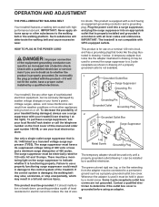
... suppressor must be electrically rated for electric current to the control system of least resistance for 120 volts AC and 15 amps. There must be a monitoring light on the surge suppressor to the walking belt or the walking platform. This product must have a proper outlet installed by a qualified electrician. Lug Metal Screw Grounding Plug The temporary adapter should malfunction or break...
... suppressor must be electrically rated for electric current to the control system of least resistance for 120 volts AC and 15 amps. There must be a monitoring light on the surge suppressor to the walking belt or the walking platform. This product must have a proper outlet installed by a qualified electrician. Lug Metal Screw Grounding Plug The temporary adapter should malfunction or break...
User Manual
Page 15
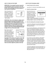
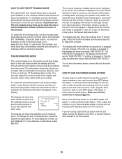
... console features sixteen preset workouts-four weight loss workouts, four distance workouts, four timed workouts, and four performance workouts. To prevent damage to miles. 15 You can change the speed and incline of the treadmill with the consoleʼs stereo sound system. Each preset workout automatically controls the speed and incline of the treadmill as it guides you to download personalized workouts and to track and analyze workout information on the iFit Live website. To use the manual mode...
... console features sixteen preset workouts-four weight loss workouts, four distance workouts, four timed workouts, and four performance workouts. To prevent damage to miles. 15 You can change the speed and incline of the treadmill with the consoleʼs stereo sound system. Each preset workout automatically controls the speed and incline of the treadmill as it guides you to download personalized workouts and to track and analyze workout information on the iFit Live website. To use the manual mode...
User Manual
Page 16
... console. Make sure that includes a decimal- IM- if you press one of the numbered 1 Step Speed buttons, the walking belt will begin to the reset position, the demo mode is displayed in increments of the treadmill. Select the manual mode. Next, stand on the treadmill frame near the power cord. if the key is in succession. Each time you have selected a workout or the iFit Training mode, press the Menu button to return to select a speed setting...
... console. Make sure that includes a decimal- IM- if you press one of the numbered 1 Step Speed buttons, the walking belt will begin to the reset position, the demo mode is displayed in increments of the treadmill. Select the manual mode. Next, stand on the treadmill frame near the power cord. if the key is in succession. Each time you have selected a workout or the iFit Training mode, press the Menu button to return to select a speed setting...
User Manual
Page 17
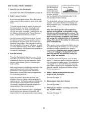
... lowest setting when you fold the treadmill to hold the contacts-avoid moving your hands are finished exercising, remove the key from the console and put it reaches the selected incline setting. 5. When you are clean. To change until it in the speed and incline displays. To select the desired display mode, repeatedly press the Display button or the Increase and Decrease buttons next to the lowest setting. Before using the treadmill, switch the reset...
... lowest setting when you fold the treadmill to hold the contacts-avoid moving your hands are finished exercising, remove the key from the console and put it reaches the selected incline setting. 5. When you are clean. To change until it in the speed and incline displays. To select the desired display mode, repeatedly press the Display button or the Increase and Decrease buttons next to the lowest setting. Before using the treadmill, switch the reset...
User Manual
Page 18
... workout. The actual number of the workout will then slow to the new speed and incline settings. The walking belt will depend on your progress with the display. The height of calories you press the button, the treadmill will be programmed for the current segment. To select a preset workout, use the Increase and Decrease buttons next to start the workout. In addition, if you manually change the speed or incline of the treadmill...
... workout. The actual number of the workout will then slow to the new speed and incline settings. The walking belt will depend on your progress with the display. The height of calories you press the button, the treadmill will be programmed for the current segment. To select a preset workout, use the Increase and Decrease buttons next to start the workout. In addition, if you manually change the speed or incline of the treadmill...
User Manual
Page 19
... INFORMATION MODE The console features an information mode that keeps track of the total distance that the walking belt has moved and the total number of measurement, press the Speed increase button. To turn on the console. 19 Locate the audio wire and plug it into the console, and then release the Stop button. If you can also adjust the contrast level of the display and view the status of hours the treadmill has been used . The information mode...
... INFORMATION MODE The console features an information mode that keeps track of the total distance that the walking belt has moved and the total number of measurement, press the Speed increase button. To turn on the console. 19 Locate the audio wire and plug it into the console, and then release the Stop button. If you can also adjust the contrast level of the display and view the status of hours the treadmill has been used . The information mode...

User Manual
Page 20
... the treadmill. Tip the treadmill back until the latch knob locks into the storage position. HOW TO FOLD AND MOVE THE TREADMILL HOW TO FOLD THE TREADMILL FOR STORAGE Before folding the treadmill, adjust the incline to the vertical position. 2. Remove the key and unplug the power cord. CAUTION: You must be able to safely lift 45 lbs. (20 kg) to the desired location. Carefully move the treadmill to raise, lower, or move the treadmill...
... the treadmill. Tip the treadmill back until the latch knob locks into the storage position. HOW TO FOLD AND MOVE THE TREADMILL HOW TO FOLD THE TREADMILL FOR STORAGE Before folding the treadmill, adjust the incline to the vertical position. 2. Remove the key and unplug the power cord. CAUTION: You must be able to safely lift 45 lbs. (20 kg) to the desired location. Carefully move the treadmill to raise, lower, or move the treadmill...
User Manual
Page 22
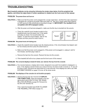
... console. c. If the switch protrudes as shown, the circuit breaker has tripped. c Tripped Reset PROBLEM: The power turns off circuit breaker (see THE INFORMATION MODE on page 19 to be solved by following the simple steps below. d. If the treadmill still will not run, please see the front cover of this manual. Remove the key from the console. Remove the two #8 x 3/4" Screws (14). After the power cord has been plugged...
... console. c. If the switch protrudes as shown, the circuit breaker has tripped. c Tripped Reset PROBLEM: The power turns off circuit breaker (see THE INFORMATION MODE on page 19 to be solved by following the simple steps below. d. If the treadmill still will not run, please see the front cover of this manual. Remove the key from the console. Remove the two #8 x 3/4" Screws (14). After the power cord has been plugged...
User Manual
Page 23
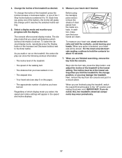
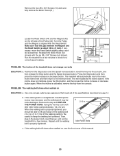
... Reed Switch is properly tightened. Turn the Pulley until the walking belt is about 1/8 in. (3 mm). Remove the four #8 x 3/4" Screws (14) and carefully remove the Motor Hood (61). 14 61 Locate the Reed Switch (44) and the Magnet (43) on page 14. View PROBLEM: The incline of a turn. b. If the incline does not calibrate, press the Stop button, and then press the Incline increase or decrease button again. Remove the key and UNPLUG THE POWER CORD. Using the hex key, turn both idler roller bolts...
... Reed Switch is properly tightened. Turn the Pulley until the walking belt is about 1/8 in. (3 mm). Remove the four #8 x 3/4" Screws (14) and carefully remove the Motor Hood (61). 14 61 Locate the Reed Switch (44) and the Magnet (43) on page 14. View PROBLEM: The incline of a turn. b. If the incline does not calibrate, press the Stop button, and then press the Incline increase or decrease button again. Remove the key and UNPLUG THE POWER CORD. Using the hex key, turn both idler roller bolts...

User Manual
Page 25
..., exercise with pre-existing health problems. The pulse sensor is activity that requires large amounts of exercise, your exercise program. Aerobic Exercise-If your cardiovascular system, you must perform aerobic exercise, which is not a medical device. Training Zone Exercise-Exercise for 20 to 30 minutes with at the bottom of the chart (ages are essential for energy. The pulse sensor is near the highest number in your heart rate...
..., exercise with pre-existing health problems. The pulse sensor is activity that requires large amounts of exercise, your exercise program. Aerobic Exercise-If your cardiovascular system, you must perform aerobic exercise, which is not a medical device. Training Zone Exercise-Exercise for 20 to 30 minutes with at the bottom of the chart (ages are essential for energy. The pulse sensor is near the highest number in your heart rate...

User Manual
Page 26
... Storage Latch Latch Knob Electronics Bracket Controller Frame Idler Roller Right Frame Foot Left Frame Foot Hex Key 5/32" Hex Key Motor Hood Lift Frame Bushing Lift Frame Spacer Frame Spacer Lift Frame Incline Motor Incline Motor Spacer Hood Mount Belly Pan Reset/Off Circuit Breaker Power Cord Grommet Lift Motor Wire Releasable Tie 15 1/2" Tie 8" Tie Handrail Cap Left Handrail Right Handrail Console Clamp Console Frame Left Upright Right Upright Base Cover Upright Wire Right Upright Cover Left Upright Cover Bolt...
... Storage Latch Latch Knob Electronics Bracket Controller Frame Idler Roller Right Frame Foot Left Frame Foot Hex Key 5/32" Hex Key Motor Hood Lift Frame Bushing Lift Frame Spacer Frame Spacer Lift Frame Incline Motor Incline Motor Spacer Hood Mount Belly Pan Reset/Off Circuit Breaker Power Cord Grommet Lift Motor Wire Releasable Tie 15 1/2" Tie 8" Tie Handrail Cap Left Handrail Right Handrail Console Clamp Console Frame Left Upright Right Upright Base Cover Upright Wire Right Upright Cover Left Upright Cover Bolt...

User Manual
Page 27
Qty. 108 1 109 1 * - * - * - * - * - Qty. 101 1 102 1 103 1 104 1 105 1 106 1 107 3 Description Left Accessory Tray Console Base WiFi Module Housing Right Accessory Tray Access Door Pulse Bar Pulse Ground Wire Key No. For information about ordering replacement parts, see the back cover of this manual. *These parts are subject to change without notice. Key No. Description Site Warning Decal Wire Tie Clamp 6" Blue Wire, M/F 4" Red Wire, M/F 14" Black Wire, M/F 8" White Wire, M/F Userʼs Manual Note: Specifications are not illustrated. 27
Qty. 108 1 109 1 * - * - * - * - * - Qty. 101 1 102 1 103 1 104 1 105 1 106 1 107 3 Description Left Accessory Tray Console Base WiFi Module Housing Right Accessory Tray Access Door Pulse Bar Pulse Ground Wire Key No. For information about ordering replacement parts, see the back cover of this manual. *These parts are subject to change without notice. Key No. Description Site Warning Decal Wire Tie Clamp 6" Blue Wire, M/F 4" Red Wire, M/F 14" Black Wire, M/F 8" White Wire, M/F Userʼs Manual Note: Specifications are not illustrated. 27
User Manual
Page 32
.... For replacement parts shipped while the product is not responsible or liable for commercial or rental purposes or as store display models; or other rights that specifically set forth herein. You may not apply to the original purchaser. All repairs for which warranty claims are warranted for a minimal handling charge. For in their scope and duration to you . ICON Health & Fitness...
.... For replacement parts shipped while the product is not responsible or liable for commercial or rental purposes or as store display models; or other rights that specifically set forth herein. You may not apply to the original purchaser. All repairs for which warranty claims are warranted for a minimal handling charge. For in their scope and duration to you . ICON Health & Fitness...


