NP115 : RS232 codes- Projectors
Page 1
... control the functions of Commands 5. Command Descriptions 6. Control Commands for NEC Projector (Basic) Rev 02.03.11a Copyright (C) NEC Display Solutions, Ltd. 2002-2010 Updated on February 3, 2011 This file contains information about NEC projector control commands. Interface Conditions 4. List of the projector via connection with a personal computer or another device. Model Name GT60 : GT5000.../NP216 Series NP64 : NP43/NP64 Series M300: M260X/M260W/M300X/M300W Series P420 P350X/P350W /P420X Series Contents 1. Table of Response Error Codes 1. Projector Control 2.
... control the functions of Commands 5. Command Descriptions 6. Control Commands for NEC Projector (Basic) Rev 02.03.11a Copyright (C) NEC Display Solutions, Ltd. 2002-2010 Updated on February 3, 2011 This file contains information about NEC projector control commands. Interface Conditions 4. List of the projector via connection with a personal computer or another device. Model Name GT60 : GT5000.../NP216 Series NP64 : NP43/NP64 Series M300: M260X/M260W/M300X/M300W Series P420 P350X/P350W /P420X Series Contents 1. Table of Response Error Codes 1. Projector Control 2.
NP115 : RS232 codes- Projectors
Page 2
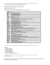
... USB port on the projector A USB cable is required Status of connection methods are required. 3-2. LAN connection 3-1. LAN connection using the LAN port on the projector A serial cable is required. 3-4. 2. LAN connection using the serial port on the projector A LAN cable is required. 2. LAN connection using a wireless LAN card A wireless LAN card is required. 3-3.LAN connection using a wireless LAN...
... USB port on the projector A USB cable is required Status of connection methods are required. 3-2. LAN connection 3-1. LAN connection using the LAN port on the projector A serial cable is required. 3-4. 2. LAN connection using the serial port on the projector A LAN cable is required. 2. LAN connection using a wireless LAN card A wireless LAN card is required. 3-3.LAN connection using a wireless LAN...
NP115 : RS232 codes- Projectors
Page 4
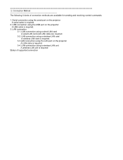
...) (!1) Before making connections, be sure to the RS-232C standard. Interface Conditions Serial connection The communications method conforms to select [NORMAL] for [STANDBY MODE]. The projector cannot use the control commands in the standby mode. (CAUTION) Before making connections, be sure to invalidate... the standby mode of PC 8 * 2, 3, 5, 6, and 8 are used inside the projector. [ GT/LT80/MT/NP1000/VT (...
...) (!1) Before making connections, be sure to the RS-232C standard. Interface Conditions Serial connection The communications method conforms to select [NORMAL] for [STANDBY MODE]. The projector cannot use the control commands in the standby mode. (CAUTION) Before making connections, be sure to invalidate... the standby mode of PC 8 * 2, 3, 5, 6, and 8 are used inside the projector. [ GT/LT80/MT/NP1000/VT (...

NP115 : RS232 codes- Projectors
Page 6
... notification) Entering 00H or FFH becomes a common command for all others "broadcast notification" is a model code for controlling multiple projectors at the same time. * When the controller is connected with multiple projectors To control a certain projector, use "individual notification". CAUTION : To notify individually, specifying a model code from the following model codes is required. * Model...
... notification) Entering 00H or FFH becomes a common command for all others "broadcast notification" is a model code for controlling multiple projectors at the same time. * When the controller is connected with multiple projectors To control a certain projector, use "individual notification". CAUTION : To notify individually, specifying a model code from the following model codes is required. * Model...
NP115 : RS232 codes- Projectors
Page 43
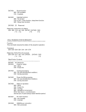
... state transition period DATA07 PC Card insertion 00H : Not inserted 01H : Inserted DATA08 USB Mouse connection 00H : Not connected DATA16 CKS (*1) (*2) (*3) Data Portion Contents DATA01 .. 02 Reserved DATA03 Projector status 00H : Idling 01H : Power On DATA04 Cooling processing 00H : No execution(Normal condition) ...Timer function, sleep timer function 02H : Sleep timer function DATA06 .. 32 Reserved Response: At the time of the projector operation. RUNNING STATUS REQUEST Function: This command acquires the status of a failure A0H 85H 01H xxH 02H DATA01 DATA02 CKS (*1) (*2) (*4) ...
... state transition period DATA07 PC Card insertion 00H : Not inserted 01H : Inserted DATA08 USB Mouse connection 00H : Not connected DATA16 CKS (*1) (*2) (*3) Data Portion Contents DATA01 .. 02 Reserved DATA03 Projector status 00H : Idling 01H : Power On DATA04 Cooling processing 00H : No execution(Normal condition) ...Timer function, sleep timer function 02H : Sleep timer function DATA06 .. 32 Reserved Response: At the time of the projector operation. RUNNING STATUS REQUEST Function: This command acquires the status of a failure A0H 85H 01H xxH 02H DATA01 DATA02 CKS (*1) (*2) (*4) ...
NP115 : RS232 codes- Projectors
Page 44
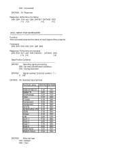
...(S-Video) 02H 03H DATA05 Entry list type 01H : Default 02H : User Command: 00H 85H 00H 00H 01H 02H 88H Response: At the time of the projector. 01H : Connected DATA09 .. 16 Reserved Response: At the time of a failure A0H 85H 01H xxH 02H DATA01 DATA02 CKS (*1) (*2) (*4) (*3) 078-3.
...(S-Video) 02H 03H DATA05 Entry list type 01H : Default 02H : User Command: 00H 85H 00H 00H 01H 02H 88H Response: At the time of the projector. 01H : Connected DATA09 .. 16 Reserved Response: At the time of a failure A0H 85H 01H xxH 02H DATA01 DATA02 CKS (*1) (*2) (*4) (*3) 078-3.
NP216 : NP01UCM (ceiling mount) instructions
Page 9
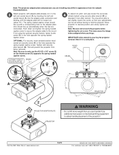
... screw. Store it , to hold the projector. WOOD JOIST CEILING SET SCREW CAPTIVE SCREW A PROJECTOR 2 1 PROJECTOR ADAPTER PLATE PROJECTOR WARNING • Do not lift more weight than you can be unaligned when you are connected). Note: The projector adapter plate and projector you let go. The spring loaded captive ... differ in a safe place. Use additional man power or mechanical lifting equipment to the mount. Visit the NEC Web Site at www.necsam.com 9 of the projector! This will no longer turn (about 75°). Note: Be sure not to just slightly loosen the screw...
... screw. Store it , to hold the projector. WOOD JOIST CEILING SET SCREW CAPTIVE SCREW A PROJECTOR 2 1 PROJECTOR ADAPTER PLATE PROJECTOR WARNING • Do not lift more weight than you can be unaligned when you are connected). Note: The projector adapter plate and projector you let go. The spring loaded captive ... differ in a safe place. Use additional man power or mechanical lifting equipment to the mount. Visit the NEC Web Site at www.necsam.com 9 of the projector! This will no longer turn (about 75°). Note: Be sure not to just slightly loosen the screw...
VT49/490/590 spec sheet
Page 1
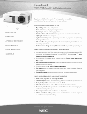
...NEC technologies like Advanced AccuBlend™ and VORTEX™ Technology, the VT Series displays impressive image quality. ° Vertical position of the image can be adjusted when the Cinema aspect (wide screen) ratio is in use of a button. ° Optional IR receiver can be connected to projector...TO USE AUTOSENSE TECHNOLOGY MONITOR OUTPUT COLOR MANAGEMENT QUICK START Easy does it VT49, VT491 and VT590 digital projectors. SAVE MONEY, RESOURCES AND YOUR PROJECTOR. ° The VT Series projectors are extremely affordable. ° Extended lamp life with Eco-mode™ technology ...
...NEC technologies like Advanced AccuBlend™ and VORTEX™ Technology, the VT Series displays impressive image quality. ° Vertical position of the image can be adjusted when the Cinema aspect (wide screen) ratio is in use of a button. ° Optional IR receiver can be connected to projector...TO USE AUTOSENSE TECHNOLOGY MONITOR OUTPUT COLOR MANAGEMENT QUICK START Easy does it VT49, VT491 and VT590 digital projectors. SAVE MONEY, RESOURCES AND YOUR PROJECTOR. ° The VT Series projectors are extremely affordable. ° Extended lamp life with Eco-mode™ technology ...
VT49/490/590 spec sheet
Page 2
...quick start guide, product registration card NEC 010707 All other trademarks are connected to 5 foot adjustable extension column for use with projector mount SCP100 Adjustable suspended ceiling plate for projector, remote control, battteries, power ...cord, RGB signal cable, lens cap, user's manual on labor. OPTICAL Display Technology Resolution Light Output (lumens) Contrast Ratio Lamp Type Lamp Life (up to) Screen Size (diagonal) Throw Ratio Projection Distance Projection Angle Lens Keystone Correction 0.6" LCD Native: VT49/VT491: SVGA...
...quick start guide, product registration card NEC 010707 All other trademarks are connected to 5 foot adjustable extension column for use with projector mount SCP100 Adjustable suspended ceiling plate for projector, remote control, battteries, power ...cord, RGB signal cable, lens cap, user's manual on labor. OPTICAL Display Technology Resolution Light Output (lumens) Contrast Ratio Lamp Type Lamp Life (up to) Screen Size (diagonal) Throw Ratio Projection Distance Projection Angle Lens Keystone Correction 0.6" LCD Native: VT49/VT491: SVGA...
VT491/590/595 IG
Page 6
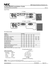
www.necdisplay.com VT491/590/595 Page 6 of America, Inc. NOTE 2: For long cable runs it is recommended to set communication speed within the projector to 9600 bps. Cable Connection Communication Protocol: Baud Rate: 38400 bps Data Length: 8... bits Parity: No Parity Stop Bit: One Bit X on/off: None Communications: Full duplex NOTE 1 : Pins 2, 3, 5, and 6 are used inside the projector. VT491/590/595 Installation Guide Ceiling Mounted and Desktop Input Panel VT595 NEC...
www.necdisplay.com VT491/590/595 Page 6 of America, Inc. NOTE 2: For long cable runs it is recommended to set communication speed within the projector to 9600 bps. Cable Connection Communication Protocol: Baud Rate: 38400 bps Data Length: 8... bits Parity: No Parity Stop Bit: One Bit X on/off: None Communications: Full duplex NOTE 1 : Pins 2, 3, 5, and 6 are used inside the projector. VT491/590/595 Installation Guide Ceiling Mounted and Desktop Input Panel VT595 NEC...
VT49/490/491/590/595/695 UM
Page 4
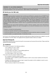
... to radio communications. Installation • Do not place the projector in the following measures: • Reorient or relocate the receiving antenna. • Increase the separation between the equipment and receiver. • Connect the equipment into an outlet on a circuit different from that... interference will expose you wish to the State of the FCC Rules. The projector must be installed by NEC Corporation of your supplier. These limits are to ...
... to radio communications. Installation • Do not place the projector in the following measures: • Reorient or relocate the receiving antenna. • Increase the separation between the equipment and receiver. • Connect the equipment into an outlet on a circuit different from that... interference will expose you wish to the State of the FCC Rules. The projector must be installed by NEC Corporation of your supplier. These limits are to ...
VT49/490/491/590/595/695 UM
Page 7
... Two Analog COMPUTER Inputs Simultaneously (VT695/VT595)-------- 15 Connecting an External Monitor 16 Connecting Your DVD Player with Component Output 17 Connecting Your VCR or Laser Disc Player 18 Connecting the Supplied Power Cable 19 3. Projecting an Image (Basic Operation 20 ᕡ Turning on the Projector 20 Note on Startup screen (Menu Language Select screen...
... Two Analog COMPUTER Inputs Simultaneously (VT695/VT595)-------- 15 Connecting an External Monitor 16 Connecting Your DVD Player with Component Output 17 Connecting Your VCR or Laser Disc Player 18 Connecting the Supplied Power Cable 19 3. Projecting an Image (Basic Operation 20 ᕡ Turning on the Projector 20 Note on Startup screen (Menu Language Select screen...
VT49/490/491/590/595/695 UM
Page 8
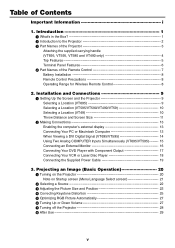
Table of D-Sub COMPUTER Input Connector 62 ᕥ Compatible Input Signal List 63 ᕦ PC Control Codes and Cable Connection 64 ᕧ Troubleshooting Check List 66 ᕨ TravelCare Guide 68 vi Maintenance 50 ᕡ Cleaning or Replacing the Filters 50 ᕢ Cleaning the Cabinet and ... 48 ᕨ Menu Descriptions & Functions [Reset 49 6. Using On-Screen Menu 36 ᕡ Using the Menus 36 ᕢ Menu Elements 38 ᕣ List of the Projector 31 ᕦ Using the Optional Remote Mouse Receiver (NP01MR 34 5.
Table of D-Sub COMPUTER Input Connector 62 ᕥ Compatible Input Signal List 63 ᕦ PC Control Codes and Cable Connection 64 ᕧ Troubleshooting Check List 66 ᕨ TravelCare Guide 68 vi Maintenance 50 ᕡ Cleaning or Replacing the Filters 50 ᕢ Cleaning the Cabinet and ... 48 ᕨ Menu Descriptions & Functions [Reset 49 6. Using On-Screen Menu 36 ᕡ Using the Menus 36 ᕢ Menu Elements 38 ᕣ List of the Projector 31 ᕦ Using the Optional Remote Mouse Receiver (NP01MR 34 5.
VT49/490/491/590/595/695 UM
Page 10
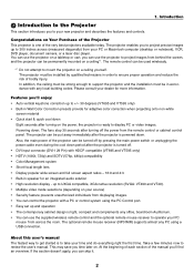
...Wall Color Correction presets provide for more information. The fans stop 30 seconds after turning on the power, the projector is to UXGA compatible, XGA native resolution (SVGA: VT490 and VT49). • Multiple video mode selections (depending on a ceiling yourself. The optional remote ...with a PC or control system using a USB connection. Features you'll enjoy: • Auto vertical keystone correction up to take your PC mouse from across (measured diagonally) from behind the screen, and the projector can control the projector with any office, boardroom Auditorium. • You...
...Wall Color Correction presets provide for more information. The fans stop 30 seconds after turning on the power, the projector is to UXGA compatible, XGA native resolution (SVGA: VT490 and VT49). • Multiple video mode selections (depending on a ceiling yourself. The optional remote ...with a PC or control system using a USB connection. Features you'll enjoy: • Auto vertical keystone correction up to take your PC mouse from across (measured diagonally) from behind the screen, and the projector can control the projector with any office, boardroom Auditorium. • You...
VT49/490/491/590/595/695 UM
Page 11
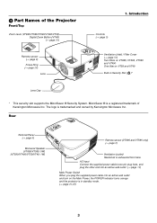
The logo is a registered trademark of the Projector Front/Top Zoom Lever (VT695/VT595/VT590/VT490/VT59) Digital Zoom Button (VT49) (→ page 24) Remote ...page 6) Monaural Speaker (VT695/VT595: 5W) (VT590/VT490/VT59/VT49: 1W) POWERSTATUSLAMP ON/STAND BY SOURCE AUTO ADJ. AC Input Connect the supplied power cable's two-pin plug here, and plug the other end into an active wall outlet. (→ page 19)... VT590 and VT490 One filter on the Main Power, the POWER indicator turns orange and the projector is exhausted from here. FOCUS ZOOM ᕣ Part Names of Kensington Microware Inc.
The logo is a registered trademark of the Projector Front/Top Zoom Lever (VT695/VT595/VT590/VT490/VT59) Digital Zoom Button (VT49) (→ page 24) Remote ...page 6) Monaural Speaker (VT695/VT595: 5W) (VT590/VT490/VT59/VT49: 1W) POWERSTATUSLAMP ON/STAND BY SOURCE AUTO ADJ. AC Input Connect the supplied power cable's two-pin plug here, and plug the other end into an active wall outlet. (→ page 19)... VT590 and VT490 One filter on the Main Power, the POWER indicator turns orange and the projector is exhausted from here. FOCUS ZOOM ᕣ Part Names of Kensington Microware Inc.
VT49/490/491/590/595/695 UM
Page 14
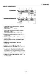
...are on page 64. 9. MONITOR OUT Connector (Mini D-Sub 15 Pin) (→page 16) 5. VIDEO IN Connector (RCA) (→page 18) 7. If you to connect a PC or control system. COMPUTER 2 (DVI-I) IN (DVI-I ) IN AUDIO IN COMPUTER 1 IN R VIDEO IN AUDIO IN AUDIO OUT MONITOR OUT (COMP 1) 67...Mini) (→page 13,14,17) (VT695/VT595) 3. PC CONTROL Port (DIN 8 Pin) (→page 64,65) Use this port to control the projector using serial communication protocol. Introduction 6 Terminal Panel Features VT695/VT595 VT590/VT490/VT59/VT49 5 S-VIDEO L IN 8 921 PC CTRL COMPUTER 2 (DVI-I 29 ...
...are on page 64. 9. MONITOR OUT Connector (Mini D-Sub 15 Pin) (→page 16) 5. VIDEO IN Connector (RCA) (→page 18) 7. If you to connect a PC or control system. COMPUTER 2 (DVI-I) IN (DVI-I ) IN AUDIO IN COMPUTER 1 IN R VIDEO IN AUDIO IN AUDIO OUT MONITOR OUT (COMP 1) 67...Mini) (→page 13,14,17) (VT695/VT595) 3. PC CONTROL Port (DIN 8 Pin) (→page 64,65) Use this port to control the projector using serial communication protocol. Introduction 6 Terminal Panel Features VT695/VT595 VT590/VT490/VT59/VT49 5 S-VIDEO L IN 8 921 PC CTRL COMPUTER 2 (DVI-I 29 ...

VT49/490/491/590/595/695 UM
Page 17
... the lens with the lens cap. ᕡ Setting Up the Screen and the Projector Selecting a Location (VT695) The further your projector and how to the projector. (→ page 13,14,15,16,17,18) 3 Connect the supplied power cable. (→ page 19) NOTE: Ensure that the power ... the image can be is 300" (7.6 m) when the projector is roughly 38 inches (1.0 m) from the wall or screen. Installation and Connections This section describes how to set up a screen and the projector. 2 Connect your computer or video equipment to connect video and audio sources. Use as a rule of thumb....
... the lens with the lens cap. ᕡ Setting Up the Screen and the Projector Selecting a Location (VT695) The further your projector and how to the projector. (→ page 13,14,15,16,17,18) 3 Connect the supplied power cable. (→ page 19) NOTE: Ensure that the power ... the image can be is 300" (7.6 m) when the projector is roughly 38 inches (1.0 m) from the wall or screen. Installation and Connections This section describes how to set up a screen and the projector. 2 Connect your computer or video equipment to connect video and audio sources. Use as a rule of thumb....

VT49/490/491/590/595/695 UM
Page 18
... center POWERSTATUSLAMP ON/STAND BY SOURCE AUTO ADJ. Use as a rule of thumb. • Digital Zoom can be is 300" (7.6 m) when the projector is roughly 30 inches (0.8 m) from the wall or screen. Use as a guide. The largest the image can be is approximately 25" (0.64 m)... m/inch) 10.2/402 TIP: • The distances are indicated by intermediate values between tele and wide. Installation and Connections Selecting a Location (VT595/VT590/VT490/VT59) The further your projector is about 434 inches (11.0 m) from the wall or screen. The minimum size the image can result in a...
... center POWERSTATUSLAMP ON/STAND BY SOURCE AUTO ADJ. Use as a rule of thumb. • Digital Zoom can be is 300" (7.6 m) when the projector is roughly 30 inches (0.8 m) from the wall or screen. Use as a guide. The largest the image can be is approximately 25" (0.64 m)... m/inch) 10.2/402 TIP: • The distances are indicated by intermediate values between tele and wide. Installation and Connections Selecting a Location (VT595/VT590/VT490/VT59) The further your projector is about 434 inches (11.0 m) from the wall or screen. The minimum size the image can result in a...
VT49/490/491/590/595/695 UM
Page 19
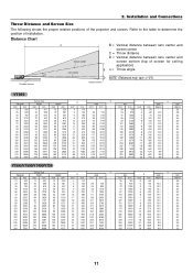
Installation and Connections Throw Distance and Screen Size The following shows the proper relative positions of installation. Refer to the table to determine the position of the projector and screen. tele D α wide tele inch mm inch mm degree - Screen bottom VT695 Screen Size ... 6858 216 5486 162 4115 56 1410 318 8070 - 300 7620 240 6096 180 4572 62 1570 353 8970 - Distance Chart α Projector bottom C Screen center Lens center B = Vertical distance between lens center and screen center C = Throw distance D = Vertical distance between lens...
Installation and Connections Throw Distance and Screen Size The following shows the proper relative positions of installation. Refer to the table to determine the position of the projector and screen. tele D α wide tele inch mm inch mm degree - Screen bottom VT695 Screen Size ... 6858 216 5486 162 4115 56 1410 318 8070 - 300 7620 240 6096 180 4572 62 1570 353 8970 - Distance Chart α Projector bottom C Screen center Lens center B = Vertical distance between lens center and screen center C = Throw distance D = Vertical distance between lens...

VT49/490/491/590/595/695 UM
Page 20
Installation and Connections C inch mm 35 890 42 1070 57 1440 86 2180 103 2620 115 2920 121 3060 129 3290 144 3650 173 4390 217 5500 260 ...˚C) (Eco mode selected automatically at 95˚F to 104˚F/35˚C to 40˚C). • Do not expose the projector to the ground, you can dissipate. Contact your NEC dealer if you 're using a mirror system and your remote control to correct the orientation. (→ page 45) 12 If the...
Installation and Connections C inch mm 35 890 42 1070 57 1440 86 2180 103 2620 115 2920 121 3060 129 3290 144 3650 173 4390 217 5500 260 ...˚C) (Eco mode selected automatically at 95˚F to 104˚F/35˚C to 40˚C). • Do not expose the projector to the ground, you can dissipate. Contact your NEC dealer if you 're using a mirror system and your remote control to correct the orientation. (→ page 45) 12 If the...


