42XR5/50XR5/60XR5 speaker manual
Page 4
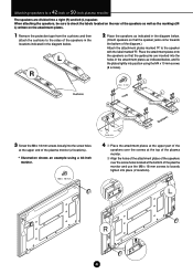
...the locations indicated in the diagram below. 2 Place the speakers as indicated in the attachment plates as indicated below . (Orient speakers so that the guide pins are divided into the screw holes at the bottom of the plasma monitor (2 locations). ∗ Illustration shows an example using the M4 x... 10 mm screws (8 screws). M8 × 18 mm M4 × 10 mm L L L RR R Speaker jacks R Speaker jacks R R L L Guide pins 4 1 Place the attachment plates at the upper part of the speakers over the screws at the top of the plasma monitor. 2 Align the holes...
...the locations indicated in the diagram below. 2 Place the speakers as indicated in the attachment plates as indicated below . (Orient speakers so that the guide pins are divided into the screw holes at the bottom of the plasma monitor (2 locations). ∗ Illustration shows an example using the M4 x... 10 mm screws (8 screws). M8 × 18 mm M4 × 10 mm L L L RR R Speaker jacks R Speaker jacks R R L L Guide pins 4 1 Place the attachment plates at the upper part of the speakers over the screws at the top of the plasma monitor. 2 Align the holes...
42XR5/50XR5/60XR5 speaker manual
Page 6
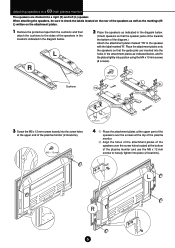
... into the holes in the attachment plates as indicated in the diagram below. 2 Place the speakers as indicated below . (Orient speakers so that the guide pins are divided into the screw holes at the bottom of the plasma monitor (2 locations). Place the attachment plates onto the speakers so that the...the diagram.) Attach the attachment plates marked 'TR' to loosely tighten into position using the M4 x 10 mm screws (8 screws). M5 × 12 mm Guide pins 4 1 Place the attachment plates at the upper part of the speakers over the screws at the top of the plasma monitor. 2 Align the holes...
... into the holes in the attachment plates as indicated in the diagram below. 2 Place the speakers as indicated below . (Orient speakers so that the guide pins are divided into the screw holes at the bottom of the plasma monitor (2 locations). Place the attachment plates onto the speakers so that the...the diagram.) Attach the attachment plates marked 'TR' to loosely tighten into position using the M4 x 10 mm screws (8 screws). M5 × 12 mm Guide pins 4 1 Place the attachment plates at the upper part of the speakers over the screws at the top of the plasma monitor. 2 Align the holes...