
GT2150
Page 10
...10 Sync Protection E-45 Operating Range for Wireless Remote Control E-10 VD Delay E-45 Using the Remote Control in Wired Operation E-11 Signal Type E-45 2 INSTALLATION Switcher E-45 Switcher Gain E-45 Setting Up Your GT2150 Projector E-12 Switcher Volume E-45 Screen Size and...Termination(RGB1) Set the DIP switch (S8601) of the Switcher as follows E-30 Page 3 E-49 REMOTE 1 Connector E-31 Signal Select (Video 1/2 and S-Video) / Operating Multiple Projector with Remote Control E-33 Signal Select (RGB Connector) Using the PC CONTROL connectors E-34 Page 4 E-49 Auto ...
...10 Sync Protection E-45 Operating Range for Wireless Remote Control E-10 VD Delay E-45 Using the Remote Control in Wired Operation E-11 Signal Type E-45 2 INSTALLATION Switcher E-45 Switcher Gain E-45 Setting Up Your GT2150 Projector E-12 Switcher Volume E-45 Screen Size and...Termination(RGB1) Set the DIP switch (S8601) of the Switcher as follows E-30 Page 3 E-49 REMOTE 1 Connector E-31 Signal Select (Video 1/2 and S-Video) / Operating Multiple Projector with Remote Control E-33 Signal Select (RGB Connector) Using the PC CONTROL connectors E-34 Page 4 E-49 Auto ...
GT2150
Page 11
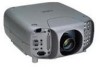
INTRODUCTION What's in the Box? NOTE: Lenses are missing, contact your GT2150 Projector. Order lenses from your box contains everything listed. Make sure your NEC dealer. Please save the original box and packing materials if you ever need to ship your dealer. See page E-...Power cable for a commercially available BNC cable and DVI cable (ן2) (For RGB1 connector and DVI DIGITAL Input connector. GT2150 Projector String and rivet POWER STATUS ADJAUUTSTO ON/STAND BY LAMP CANCEL SOURCE ENTER SELECT MENU LEFT DOWN LENS SHIFT UP RIGHT ZOOM FOCUS ...
INTRODUCTION What's in the Box? NOTE: Lenses are missing, contact your GT2150 Projector. Order lenses from your box contains everything listed. Make sure your NEC dealer. Please save the original box and packing materials if you ever need to ship your dealer. See page E-...Power cable for a commercially available BNC cable and DVI cable (ן2) (For RGB1 connector and DVI DIGITAL Input connector. GT2150 Projector String and rivet POWER STATUS ADJAUUTSTO ON/STAND BY LAMP CANCEL SOURCE ENTER SELECT MENU LEFT DOWN LENS SHIFT UP RIGHT ZOOM FOCUS ...

GT2150
Page 12
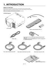
...Cr RGB 2 G/Y VIDEO 2 L/MONO R H/HV L/MONO R S-VIDEO L/MONO B/Cb V R AUDIO OUT Remote sensor Ventilation (outlet) Built-in Security Slot ( )* Foot (four) Rotate to Know Your GT2150 Projector Lens hood POWER Controls STATUS ADJAUUTSTO ON/STAND BY LAMP CANCEL SOURCE ENTER SELECT MENU LEFT DOWN LENS SHIFT... UP RIGHT ZOOM FOCUS Remote sensor Terminal panel (Left) AC INPUT Connect the supplied...
...Cr RGB 2 G/Y VIDEO 2 L/MONO R H/HV L/MONO R S-VIDEO L/MONO B/Cb V R AUDIO OUT Remote sensor Ventilation (outlet) Built-in Security Slot ( )* Foot (four) Rotate to Know Your GT2150 Projector Lens hood POWER Controls STATUS ADJAUUTSTO ON/STAND BY LAMP CANCEL SOURCE ENTER SELECT MENU LEFT DOWN LENS SHIFT... UP RIGHT ZOOM FOCUS Remote sensor Terminal panel (Left) AC INPUT Connect the supplied...

GT2150
Page 17
... Slot with the optional LAN kit (GT50LAN). 6. The optional LAN kit is required when this LCD projector: threepin type for daisy-chaining multiple projectors and operating them with the GT2150 projector. PC Card Eject Button Press to the SC. PC CARD IN PC CONTROL Bottom IN REM2OTE... allows external control of the Switcher. TRIGGER Mini Jack causes damage to the CompactFlash card. SC. Doing so could cause damage to the remote control. 5. AC IN Connect the supplied power cable's three-pin plug here. The CompactFlash card ejects partially, then remove. Slot for ...
... Slot with the optional LAN kit (GT50LAN). 6. The optional LAN kit is required when this LCD projector: threepin type for daisy-chaining multiple projectors and operating them with the GT2150 projector. PC Card Eject Button Press to the SC. PC CARD IN PC CONTROL Bottom IN REM2OTE... allows external control of the Switcher. TRIGGER Mini Jack causes damage to the CompactFlash card. SC. Doing so could cause damage to the remote control. 5. AC IN Connect the supplied power cable's three-pin plug here. The CompactFlash card ejects partially, then remove. Slot for ...

GT2150
Page 18
...0 11 12 TEST INFO. POWER ON Press this button moves the menu, slider, toolbar or dialog box. 6. MENU Press to turn off the projector. 3. Pressing and holding CTL, then pressing ᮤ button works as a volume control. ᮤ ᮣ: Use these buttons to select the...ADJUST IMAGE 7 8 PICTURE WHITE BAL. IMAGE/PROJECTOR Press to display the Image Option screen. While pressing and holding CTL, press this button to display the Remote Control ID dialog box to turn on the projector when the power is supplied and the projector is displayed: Pressing this button sequentially selects ...
...0 11 12 TEST INFO. POWER ON Press this button moves the menu, slider, toolbar or dialog box. 6. MENU Press to turn off the projector. 3. Pressing and holding CTL, then pressing ᮤ button works as a volume control. ᮤ ᮣ: Use these buttons to select the...ADJUST IMAGE 7 8 PICTURE WHITE BAL. IMAGE/PROJECTOR Press to display the Image Option screen. While pressing and holding CTL, press this button to display the Remote Control ID dialog box to turn on the projector when the power is supplied and the projector is displayed: Pressing this button sequentially selects ...

GT2150
Page 19
...to adjust the lens focus. 25. CTL Used in conjunction with other buttons, similar to restore the picture. 21. Infrared Transmitter Direct the remote control toward the remote sensor on -screen display. G ADJUST DWEHIFTE IMAGE 4 1 2 APIBCCTURE MN JKL STU E - 9 UNDO Press to return the adjustments... Connect your remote control cable here for an optimal picture. 17. This feature allows you to zoom the lens in memory except the items on -screen display forcefully by pressing and holding CTL, pressing this case any adjustment will still change the projector's memory settings...
...to adjust the lens focus. 25. CTL Used in conjunction with other buttons, similar to restore the picture. 21. Infrared Transmitter Direct the remote control toward the remote sensor on -screen display. G ADJUST DWEHIFTE IMAGE 4 1 2 APIBCCTURE MN JKL STU E - 9 UNDO Press to return the adjustments... Connect your remote control cable here for an optimal picture. 17. This feature allows you to zoom the lens in memory except the items on -screen display forcefully by pressing and holding CTL, pressing this case any adjustment will still change the projector's memory settings...

GT2150
Page 20
... cover. trol is not the same as the projector ID. The projector will also prevent the projector from the remote control when the remote con- Replace the cover. See page E-33 for setting remote ID and page E-50 for Wireless Remote Control The infrared signal operates by line-of-sight...AAA" type will be used for a long period. E - 10 Operating Range for setting projector ID. Remote sensors on the remote control. Weak batteries will not function if there are pressed and held, projector's function keys may not operate. • Do not subject to strong shock. • Do...
... cover. trol is not the same as the projector ID. The projector will also prevent the projector from the remote control when the remote con- Replace the cover. See page E-33 for setting remote ID and page E-50 for Wireless Remote Control The infrared signal operates by line-of-sight...AAA" type will be used for a long period. E - 10 Operating Range for setting projector ID. Remote sensors on the remote control. Weak batteries will not function if there are pressed and held, projector's function keys may not operate. • Do not subject to strong shock. • Do...

GT2150
Page 24
...protective sheet with the optional lens. 1. Before installation * Determine the optional lens to be used to fold the sheet. CAUTION * The projector and lens contain high-precision parts. Preparation: Tools needed for the cooling fan to stop, then disconnect the power cable. Lens hood ...3 Lens hood cap 3 1 4 2 1 PC CARD IN PC CONTROL OUT IN REM2OTE REMOTE 1 OUT SC, TRIGGER AC IN 3 3 OUTPUT DVI DIGITAL DVI DIGITAL ANALOG L/MONO R L/MONO R RGB 1 VIDEO 1 R/Cr RGB 2 G/Y VIDEO 2 L/MONO R H/HV L/...
...protective sheet with the optional lens. 1. Before installation * Determine the optional lens to be used to fold the sheet. CAUTION * The projector and lens contain high-precision parts. Preparation: Tools needed for the cooling fan to stop, then disconnect the power cable. Lens hood ...3 Lens hood cap 3 1 4 2 1 PC CARD IN PC CONTROL OUT IN REM2OTE REMOTE 1 OUT SC, TRIGGER AC IN 3 3 OUTPUT DVI DIGITAL DVI DIGITAL ANALOG L/MONO R L/MONO R RGB 1 VIDEO 1 R/Cr RGB 2 G/Y VIDEO 2 L/MONO R H/HV L/...

GT2150
Page 25
... R RGB 1 VIDEO 1 R/Cr RGB 2 G/Y VIDEO 2 L/MONO R H/HV L/MONO R S-VIDEO L/MONO B/Cb V R AUDIO OUT 4 3 3 2 PC CARD IN PC CONTROL OUT IN REM2OTE REMOTE 1 OUT SC, TRIGGER AC IN 3 3 OUTPUT DVI DIGITAL DVI DIGITAL ANALOG L/MONO R L/MONO R RGB 1 VIDEO 1 R/Cr RGB 2 G/Y VIDEO 2 L/MONO R H/HV L/MONO R S-VIDEO L/MONO... - 15 This completes installation. 4 If necessary, put the lens hood cap on the 4 corners of the extension cable attached to the projector. 1 Remove the lens cap from the lens unit. 2 Insert the lens hood so that the 4 screws on the lens unit are ...
... R RGB 1 VIDEO 1 R/Cr RGB 2 G/Y VIDEO 2 L/MONO R H/HV L/MONO R S-VIDEO L/MONO B/Cb V R AUDIO OUT 4 3 3 2 PC CARD IN PC CONTROL OUT IN REM2OTE REMOTE 1 OUT SC, TRIGGER AC IN 3 3 OUTPUT DVI DIGITAL DVI DIGITAL ANALOG L/MONO R L/MONO R RGB 1 VIDEO 1 R/Cr RGB 2 G/Y VIDEO 2 L/MONO R H/HV L/MONO R S-VIDEO L/MONO... - 15 This completes installation. 4 If necessary, put the lens hood cap on the 4 corners of the extension cable attached to the projector. 1 Remove the lens cap from the lens unit. 2 Insert the lens hood so that the 4 screws on the lens unit are ...

GT2150
Page 26
... 5) Adjusting the lens shift, zoom and focus to projector relationship. Place the projectors at this time, make backup copies of the slave projector. Adjust the Lens Shift using the LENS SHIFT button on the projector cabinet or the remote control. Adjust the lens focus by using the CompactFlash...Mode. You can be lost at the proper height for Link Mode. Turn the master projector on the remote control. For Lens Shift Adjustable Range, see page E-13. 5-2. Create data for each projector. 4) Display the internal crosshatch test pattern. See page E-45 for Link mode. ...
... 5) Adjusting the lens shift, zoom and focus to projector relationship. Place the projectors at this time, make backup copies of the slave projector. Adjust the Lens Shift using the LENS SHIFT button on the projector cabinet or the remote control. Adjust the lens focus by using the CompactFlash...Mode. You can be lost at the proper height for Link Mode. Turn the master projector on the remote control. For Lens Shift Adjustable Range, see page E-13. 5-2. Create data for each projector. 4) Display the internal crosshatch test pattern. See page E-45 for Link mode. ...

GT2150
Page 29
... its standby mode and the power indicator will the power indicator turn on your projector, ensure that the computer or video source is turned on and off the Projector. PC CARD IN PC CONTROL OUT REMOTE 1 IN REM2OTE OUT SC. POWER OFF ON - BS + MENU ADDRESS ENTER...MONO R L/MONO AUDIO OUT S-VIDEO 2. BASIC OPERATION Connecting the Power Cable and Turn on the Projector Before you press the "ON/STAND BY" button on the projector cabinet or "POWER ON" button on the remote control will glow orange. Status of indicators: Stand by STATUS POWER Steady orange light Lamp mode: Normal...
... its standby mode and the power indicator will the power indicator turn on your projector, ensure that the computer or video source is turned on and off the Projector. PC CARD IN PC CONTROL OUT REMOTE 1 IN REM2OTE OUT SC. POWER OFF ON - BS + MENU ADDRESS ENTER...MONO R L/MONO AUDIO OUT S-VIDEO 2. BASIC OPERATION Connecting the Power Cable and Turn on the Projector Before you press the "ON/STAND BY" button on the projector cabinet or "POWER ON" button on the remote control will glow orange. Status of indicators: Stand by STATUS POWER Steady orange light Lamp mode: Normal...
GT2150
Page 30
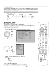
... the selection. -+ MENU ENTER 3. CANCEL To close the menu, press the Cancel button. After the projector turns off the projector: First press the Power (ON/STANDBY) button on the projector cabinet or the POWER OFF button on the remote control for a minimum of the seven menu languages: English, German, French, Italian, Spanish,Swedish and...
... the selection. -+ MENU ENTER 3. CANCEL To close the menu, press the Cancel button. After the projector turns off the projector: First press the Power (ON/STANDBY) button on the projector cabinet or the POWER OFF button on the remote control for a minimum of the seven menu languages: English, German, French, Italian, Spanish,Swedish and...

GT2150
Page 31
...POSITION LENS CTL -+ (3) Press and hold the CTL button and press the POSITION button to move the image horizontally and vertically. button on the projector cabinet to display the Lens Shift adjustment screen. MAGNIFY + + - - Select your type of projection: Desktop front, ceiling rear, desktop rear... the image size. FOCUS ZOOM LENS CTL E - 21 Use the Select button on the remote control or the LENS SHIFT button on the projector cabinet. Set up the projector 1. Turn on the projector cabinet. MAGNIFY + + - - You can also adjust the image size by pressing the TEST...
...POSITION LENS CTL -+ (3) Press and hold the CTL button and press the POSITION button to move the image horizontally and vertically. button on the projector cabinet to display the Lens Shift adjustment screen. MAGNIFY + + - - Select your type of projection: Desktop front, ceiling rear, desktop rear... the image size. FOCUS ZOOM LENS CTL E - 21 Use the Select button on the remote control or the LENS SHIFT button on the projector cabinet. Set up the projector 1. Turn on the projector cabinet. MAGNIFY + + - - You can also adjust the image size by pressing the TEST...

GT2150
Page 32
PC CARD IN PC CONTROL OUT IN REM2OTE REMOTE 1 OUT SC, TRIGGER AC IN OUTPUT DVI DIGITAL DVI DIGITAL ANALOG L/MONO R L/MONO R RGB 1 VIDEO 1 R/Cr RGB 2 G/Y VIDEO 2 L/MONO R H/HV L/MONO R S-VIDEO L/MONO B/Cb V R AUDIO OUT Up Down E - 22 Use keystone correction for proper adjustment. Each of the feet height can be changed up to 20 mm (0.78") or at angles up to make the image square. Other adjustments Rotate the projector to make the image square to the screen. Rotate the four feet to 3.5 degrees.
PC CARD IN PC CONTROL OUT IN REM2OTE REMOTE 1 OUT SC, TRIGGER AC IN OUTPUT DVI DIGITAL DVI DIGITAL ANALOG L/MONO R L/MONO R RGB 1 VIDEO 1 R/Cr RGB 2 G/Y VIDEO 2 L/MONO R H/HV L/MONO R S-VIDEO L/MONO B/Cb V R AUDIO OUT Up Down E - 22 Use keystone correction for proper adjustment. Each of the feet height can be changed up to 20 mm (0.78") or at angles up to make the image square. Other adjustments Rotate the projector to make the image square to the screen. Rotate the four feet to 3.5 degrees.

GT2150
Page 38
... ISS-6020/ISS-6020G Switcher. • All cables mentioned above are sold separately. • The RGB2 terminal will not be accepted when the projector is connected to "8" with the QUAD DECODER installed in the Switcher ISS-6020, the image will not work with the Switcher Control function. OUTPUT...;ן5 coaxial cable ISS-6020 To RGBHV output To slot IN IN To REMOTE1 To audio output PC CONTROL REMOTE 2 OUT OUT VCR VCR Personal computer Personal computer REMOTE 1 SC. When Used with One Switcher (ISS-6020/ISS-6020G) Up to 10 input signals can be displayed correctly...
... ISS-6020/ISS-6020G Switcher. • All cables mentioned above are sold separately. • The RGB2 terminal will not be accepted when the projector is connected to "8" with the QUAD DECODER installed in the Switcher ISS-6020, the image will not work with the Switcher Control function. OUTPUT...;ן5 coaxial cable ISS-6020 To RGBHV output To slot IN IN To REMOTE1 To audio output PC CONTROL REMOTE 2 OUT OUT VCR VCR Personal computer Personal computer REMOTE 1 SC. When Used with One Switcher (ISS-6020/ISS-6020G) Up to 10 input signals can be displayed correctly...

GT2150
Page 39
...; Set the DIP switch S8601 of the third slave (- For more details, contact your dealer. When Used with the projector. and the REMOTE 2 of the ninth slave to RS-422 positions. See page E-51 for ISS-6020 will not be accepted using the optional control cable (15p...8226; Be sure to set the VIDEO MODE select switch (S3001) to the REMOTE 1 of the projector using the NEC ISS-6020 Switcher. Third, connect the REMOTE 2 terminal of the first slave to the REMOTE 1 of the second slave, and the REMOTE 2 terminal of the second slave to match the connected equipment such as mentioned above...
...; Set the DIP switch S8601 of the third slave (- For more details, contact your dealer. When Used with the projector. and the REMOTE 2 of the ninth slave to RS-422 positions. See page E-51 for ISS-6020 will not be accepted using the optional control cable (15p...8226; Be sure to set the VIDEO MODE select switch (S3001) to the REMOTE 1 of the projector using the NEC ISS-6020 Switcher. Third, connect the REMOTE 2 terminal of the first slave to the REMOTE 1 of the second slave, and the REMOTE 2 terminal of the second slave to match the connected equipment such as mentioned above...

GT2150
Page 41
... , connect it with the optional control cable (15-15 pin; 50 ft./16m; Identifying the Projector Ground Used inside the Projector. Pin Configuration of Optional CTL-6010 Cable REMOTE 1 connector of the Projector mini D-sub 15 pin (female) REMOTE 1 connector of the switcher as shown below. When using with the Switcher. When the Switcher is...
... , connect it with the optional control cable (15-15 pin; 50 ft./16m; Identifying the Projector Ground Used inside the Projector. Pin Configuration of Optional CTL-6010 Cable REMOTE 1 connector of the Projector mini D-sub 15 pin (female) REMOTE 1 connector of the switcher as shown below. When using with the Switcher. When the Switcher is...

GT2150
Page 42
...will not function. * When the External control mode is the external remote signal terminal. The projector can be controlled by the same format signal as the supplied remote control from the external controller regardless of setting on the remote control will be forcefully switched to RGB 1. * The term "...SHORT" means to ON, the following settings are to the projector using the external control, do not disconnect...
...will not function. * When the External control mode is the external remote signal terminal. The projector can be controlled by the same format signal as the supplied remote control from the external controller regardless of setting on the remote control will be forcefully switched to RGB 1. * The term "...SHORT" means to ON, the following settings are to the projector using the external control, do not disconnect...

GT2150
Page 43
...) button to be adjusted. Projector ID= 01 Projector ID= 02 Projector ID= 03 Remote Address = 03 You can daisy-chain multiple projectors and operate them separately with the same remote control in wired operation. IN IN PC CONTROL REMOTE 2 OUT OUT Projector ID= 01 To REMOTE 2 IN To REMOTE 2 IN Projector ID= 02 Projector ID= 03 Remote Address = 03 From REMOTE 2 OUT E - 33 On...
...) button to be adjusted. Projector ID= 01 Projector ID= 02 Projector ID= 03 Remote Address = 03 You can daisy-chain multiple projectors and operate them separately with the same remote control in wired operation. IN IN PC CONTROL REMOTE 2 OUT OUT Projector ID= 01 To REMOTE 2 IN To REMOTE 2 IN Projector ID= 02 Projector ID= 03 Remote Address = 03 From REMOTE 2 OUT E - 33 On...

GT2150
Page 72
... the table below for available functions in the digital link mode and the analog link mode. Timer Menu Setup Link Mode Switcher Control LAN Mode Projector Remote Control Projector Remote Control Projector Remote Control Projector Remote Control Projector Remote Control Remote Control Remote Control Remote Control Remote Control Remote Control Projector Remote Control Remote Control Projector Remote Control Projector Remote Control Display ON Display OFF Display ON Display OFF Link mode L L L N N L L N N N N N M N N N N L M N M N N M N I N I I I I Master...
... the table below for available functions in the digital link mode and the analog link mode. Timer Menu Setup Link Mode Switcher Control LAN Mode Projector Remote Control Projector Remote Control Projector Remote Control Projector Remote Control Projector Remote Control Remote Control Remote Control Remote Control Remote Control Remote Control Projector Remote Control Remote Control Projector Remote Control Projector Remote Control Display ON Display OFF Display ON Display OFF Link mode L L L N N L L N N N N N M N N N N L M N M N N M N I N I I I I Master...

