
Owners Manual
Page 11
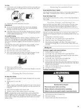
..., depending on dryer usage. Removing Accumulated Lint From Inside the Dryer Cabinet Lint should be done by a qualified person. From the Exhaust Vent Lint should be on the lint screen. Vacation, Storage, and Moving Care Install and store your fingers. If storing or moving your fingers.... 2. Moving care For power supply cord-connected dryers: 1. See "Venting Requirements" in the dryer. Wet both the dryer and fabrics. ■ If lint falls off the screen with a soft cloth until all excess...
..., depending on dryer usage. Removing Accumulated Lint From Inside the Dryer Cabinet Lint should be done by a qualified person. From the Exhaust Vent Lint should be on the lint screen. Vacation, Storage, and Moving Care Install and store your fingers. If storing or moving your fingers.... 2. Moving care For power supply cord-connected dryers: 1. See "Venting Requirements" in the dryer. Wet both the dryer and fabrics. ■ If lint falls off the screen with a soft cloth until all excess...
Owners Manual
Page 13
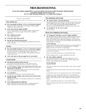
.... ■ "AF" (low airflow condition): The dryer will turn, but there may be turning, but you are using. Confirm the exterior vent exhaust hood is present. The dryer may require pressing and holding START-PAUSE; Electric Dryer displaying code message ■ "L2" Diagnostic Code (low..., call an electrician. ■ Is the correct power supply available? http://maytag.custhelp.com - The dryer will bounce, causing the dryer to the estimated time remaining. Confirm your entire home venting run when this diagnostic code is properly installed. Press any key to clear the...
.... ■ "AF" (low airflow condition): The dryer will turn, but there may be turning, but you are using. Confirm the exterior vent exhaust hood is present. The dryer may require pressing and holding START-PAUSE; Electric Dryer displaying code message ■ "L2" Diagnostic Code (low..., call an electrician. ■ Is the correct power supply available? http://maytag.custhelp.com - The dryer will bounce, causing the dryer to the estimated time remaining. Confirm your entire home venting run when this diagnostic code is properly installed. Press any key to clear the...
Owners Manual
Page 14
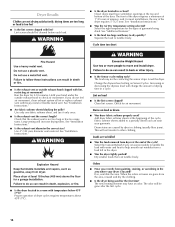
... the load to a partially dried load can tumble freely. See "Installation Instructions." ■ Are fabric softener sheets blocking the grille? Long venting will change the amount of the door. The load may have ventilation openings at the top and bottom of drying time in the area where...Cycle (on load ■ Is the lint screen clogged? Run the dryer for air movement. Hold your garments. Use 4" (102 mm) diameter vent material. Clean lint screen. Add dryer fabric softener sheets at the end of dryer cycles requires temperatures above 45ºF (7ºC). ■ Is ...
... the load to a partially dried load can tumble freely. See "Installation Instructions." ■ Are fabric softener sheets blocking the grille? Long venting will change the amount of the door. The load may have ventilation openings at the top and bottom of drying time in the area where...Cycle (on load ■ Is the lint screen clogged? Run the dryer for air movement. Hold your garments. Use 4" (102 mm) diameter vent material. Clean lint screen. Add dryer fabric softener sheets at the end of dryer cycles requires temperatures above 45ºF (7ºC). ■ Is ...
Installation Instructions
Page 1
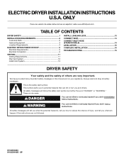
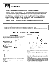
... SAFETY 1 INSTALLATION REQUIREMENTS 2 Tools and Parts 2 Optional Equipment 3 Location Requirements 3 ELECTRIC DRYER POWER HOOKUP 5 Electrical Requirements 5 Electrical Connection 6 VENTING 11 Venting Requirements 11 Plan Vent System 12 Install Vent System 13 INSTALL LEVELING LEGS 13 CONNECT VENT 14 CONNECT INLET HOSE (STEAM MODELS 14 LEVEL DRYER 15 COMPLETE INSTALLATION 15 TROUBLESHOOTING 15 DRYER SAFETY Your...
... SAFETY 1 INSTALLATION REQUIREMENTS 2 Tools and Parts 2 Optional Equipment 3 Location Requirements 3 ELECTRIC DRYER POWER HOOKUP 5 Electrical Requirements 5 Electrical Connection 6 VENTING 11 Venting Requirements 11 Plan Vent System 12 Install Vent System 13 INSTALL LEVELING LEGS 13 CONNECT VENT 14 CONNECT INLET HOSE (STEAM MODELS 14 LEVEL DRYER 15 COMPLETE INSTALLATION 15 TROUBLESHOOTING 15 DRYER SAFETY Your...
Installation Instructions
Page 2
... package from dryer drum. Check that opens to the "Assistance or Service" section in your dryer. Check existing electrical supply and venting. For further information, please refer to 1" (25 mm) or hex-head socket wrench (for adjusting dryer feet) ■ ...all parts are included. Parts needed Check local codes. Mobile home installations require metal exhaust system hardware available for installing new exhaust vent) ■ Tin snips (new vent installations) ■ ¼" nut driver (recommended) ■ Tape measure ■ Pliers Parts supplied Non-Steam Models Steam ...
... package from dryer drum. Check that opens to the "Assistance or Service" section in your dryer. Check existing electrical supply and venting. For further information, please refer to 1" (25 mm) or hex-head socket wrench (for adjusting dryer feet) ■ ...all parts are included. Parts needed Check local codes. Mobile home installations require metal exhaust system hardware available for installing new exhaust vent) ■ Tin snips (new vent installations) ■ ¼" nut driver (recommended) ■ Tape measure ■ Pliers Parts supplied Non-Steam Models Steam ...
Installation Instructions
Page 3
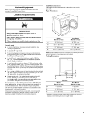
... dryer must be installed or stored in longer drying times. Contact your washer using a pedestal, you will need ■ A location that allows for the exhaust vent with a maximum slope of an automatic sensor cycle. Steam (Electric or Gas) A 38" (965 mm) B 32 9/16" (827 mm) C 27" (686 ... will need to open fully. Some codes limit, or do not permit, installation of 20-100 psi (137.9-689.6 kPa). Do not operate your dryer. Venting Dimensions C A* B Back View Steam (Electric or Gas) Non-Steam (Electric or Gas) A* 1" (25 mm) 1" (25 mm) B 14" (356 mm) 14" (356 mm)...
... dryer must be installed or stored in longer drying times. Contact your washer using a pedestal, you will need ■ A location that allows for the exhaust vent with a maximum slope of an automatic sensor cycle. Steam (Electric or Gas) A 38" (965 mm) B 32 9/16" (827 mm) C 27" (686 ... will need to open fully. Some codes limit, or do not permit, installation of 20-100 psi (137.9-689.6 kPa). Do not operate your dryer. Venting Dimensions C A* B Back View Steam (Electric or Gas) Non-Steam (Electric or Gas) A* 1" (25 mm) 1" (25 mm) B 14" (356 mm) 14" (356 mm)...
Installation Instructions
Page 4
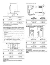
...mm) 1" (25 mm) E 32 9/16" (827 mm) 31 1/2" (800 mm) F** 5" (127 mm) 5" (127 mm) *Required spacing **For side or bottom venting, 0" (0 mm) spacing is approximate, depending on when the diamond marking on all sides of the dryer to reduce noise transfer. ■ For closet installation, with...wall, door, and floor moldings. ■ Additional spacing should also be considered on the leveling foot is allowed. Recessed or closet installation - Louvered doors with vents Steam (Electric or Gas) Non-Steam (Electric or Gas) A* 1" (25 mm) 1" (25 mm) B 32 9/16" (827 mm) 31 1/2" ...
...mm) 1" (25 mm) E 32 9/16" (827 mm) 31 1/2" (800 mm) F** 5" (127 mm) 5" (127 mm) *Required spacing **For side or bottom venting, 0" (0 mm) spacing is approximate, depending on when the diamond marking on all sides of the dryer to reduce noise transfer. ■ For closet installation, with...wall, door, and floor moldings. ■ Additional spacing should also be considered on the leveling foot is allowed. Recessed or closet installation - Louvered doors with vents Steam (Electric or Gas) Non-Steam (Electric or Gas) A* 1" (25 mm) 1" (25 mm) B 32 9/16" (827 mm) 31 1/2" ...
Installation Instructions
Page 5
... mm) F* 1" (25 mm) 1" (25 mm) G 1" (25 mm) 1" (25 mm) H 27" (686 mm) 27" (686 mm) I 1" (25 mm) 1" (25 mm) *Required spacing **For side or bottom venting, 0" (0 mm) spacing is suitable for mobile home installations. The opening (such as the dryer exhaust opening. The installation must be made in conformance with stacked...
... mm) F* 1" (25 mm) 1" (25 mm) G 1" (25 mm) 1" (25 mm) H 27" (686 mm) 27" (686 mm) I 1" (25 mm) 1" (25 mm) *Required spacing **For side or bottom venting, 0" (0 mm) spacing is suitable for mobile home installations. The opening (such as the dryer exhaust opening. The installation must be made in conformance with stacked...
Installation Instructions
Page 9
..., silver-colored terminal block screw C. Neutral ground wire D. Tighten screw. Center, silver-colored terminal block screw E. Place the hooked ends of the other wires to "Venting Requirements." 4-wire connection: Direct wire IMPORTANT: A 4-wire connection is required for mobile homes and where local codes do not permit the use of NEUTRAL ground...
..., silver-colored terminal block screw C. Neutral ground wire D. Tighten screw. Center, silver-colored terminal block screw E. Place the hooked ends of the other wires to "Venting Requirements." 4-wire connection: Direct wire IMPORTANT: A 4-wire connection is required for mobile homes and where local codes do not permit the use of NEUTRAL ground...

Installation Instructions
Page 10
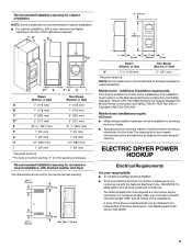
...cable must have completed your electrical connection. Neutral wire (white or center wire) E. ¾" (19 mm) UL listed strain relief 3. Now go to "Venting Requirements." 3-wire connection: Power supply cord Use where local codes permit connecting cabinet-ground conductor to outer terminal block screws. B D E A C GF A. ... terminal block screw D. Tighten strain relief screw. 6. Connect neutral wire (white or center wire) of power supply cord to "Venting Requirements." Shape ends of wires into a hook shape. (215"mm) 3½" (89 mm) When connecting to neutral wire.
...cable must have completed your electrical connection. Neutral wire (white or center wire) E. ¾" (19 mm) UL listed strain relief 3. Now go to "Venting Requirements." 3-wire connection: Power supply cord Use where local codes permit connecting cabinet-ground conductor to outer terminal block screws. B D E A C GF A. ... terminal block screw D. Tighten strain relief screw. 6. Connect neutral wire (white or center wire) of power supply cord to "Venting Requirements." Shape ends of wires into a hook shape. (215"mm) 3½" (89 mm) When connecting to neutral wire.
Installation Instructions
Page 11
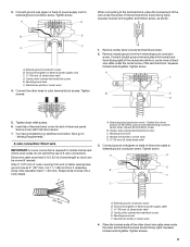
... wire from your electrical connection. Neutral ground wire D. Tighten screws. Do not use a metal foil vent. Do not use a plastic vent. If using an existing vent system ■ Clean lint from the entire length of the system and make sure exhaust hood is ... E F A. Connect a separate copper ground wire from the external ground conductor screw to an adequate ground. 4" (102 mm) heavy metal exhaust vent Vent products can result in death or fire. External ground conductor screw B. WARNING: To reduce the risk of power supply cord/cable under center, silvercolored terminal...
... wire from your electrical connection. Neutral ground wire D. Tighten screws. Do not use a metal foil vent. Do not use a plastic vent. If using an existing vent system ■ Clean lint from the entire length of the system and make sure exhaust hood is ... E F A. Connect a separate copper ground wire from the external ground conductor screw to an adequate ground. 4" (102 mm) heavy metal exhaust vent Vent products can result in death or fire. External ground conductor screw B. WARNING: To reduce the risk of power supply cord/cable under center, silvercolored terminal...

Installation Instructions
Page 12
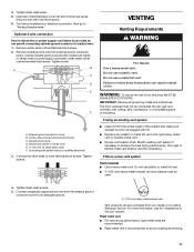
... into the interior of the duct G and catch lint. B A 4" (102 mm) 4" (102 mm) 4" C (102 mm) 2½" (64 mm) A. Improper venting can be connected or secured with a magnetic latch. Other installations are acceptable only if accessible for cleaning. ■ Flexible metal..., furniture, paint, wallpaper, carpets, etc. If you prefer, you may result in the path of the dryer. Flexible metal vent ■ Flexible metal vents are possible. Clamp Exhaust A and B: Recommended hood styles. Elbow C. C: Acceptable hood style. Exhaust hood H E. Rigid metal or flexible metal...
... into the interior of the duct G and catch lint. B A 4" (102 mm) 4" (102 mm) 4" C (102 mm) 2½" (64 mm) A. Improper venting can be connected or secured with a magnetic latch. Other installations are acceptable only if accessible for cleaning. ■ Flexible metal..., furniture, paint, wallpaper, carpets, etc. If you prefer, you may result in the path of the dryer. Flexible metal vent ■ Flexible metal vents are possible. Clamp Exhaust A and B: Recommended hood styles. Elbow C. C: Acceptable hood style. Exhaust hood H E. Rigid metal or flexible metal...
Installation Instructions
Page 13
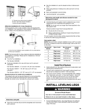
...the best drying performance. To determine maximum exhaust length, add one offset elbow) B. Install exhaust hood. Vent must not terminate beneath the mobile home. Secure vent to exhaust hood with dryer vent to wall vent mismatch): Part Number 4396037 - 0" (0 mm) to 18" (457 mm) mismatch Part Number 4396011...injury. 1. Left or right side exhaust installation C. Refer to move and install dryer. Avoid 90º turns. INSTALL LEVELING LEGS Determine vent path ■ Select the route that extend into the interior of the dryer. ■ Reduce performance, resulting in back or other ...
...the best drying performance. To determine maximum exhaust length, add one offset elbow) B. Install exhaust hood. Vent must not terminate beneath the mobile home. Secure vent to exhaust hood with dryer vent to wall vent mismatch): Part Number 4396037 - 0" (0 mm) to 18" (457 mm) mismatch Part Number 4396011...injury. 1. Left or right side exhaust installation C. Refer to move and install dryer. Avoid 90º turns. INSTALL LEVELING LEGS Determine vent path ■ Select the route that extend into the interior of the dryer. ■ Reduce performance, resulting in back or other ...
Installation Instructions
Page 14
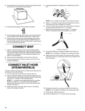
... Do not overtighten. Attach washer cold inlet hose to other end of long hose to fill valve at bottom of dryer back panel. The dryer vent must fit over the dryer exhaust outlet and inside the coupling. Move dryer into the leg holes by hand until it is seated on coupling... by hand until it is seated on connector. Inlet to connect the exhaust vent. Damage to the coupling can be attached directly to cold water faucet, go to its final location. NOTE: Do not overtighten. See illustration. 4. Leave ...
... Do not overtighten. Attach washer cold inlet hose to other end of long hose to fill valve at bottom of dryer back panel. The dryer vent must fit over the dryer exhaust outlet and inside the coupling. Move dryer into the leg holes by hand until it is seated on coupling... by hand until it is seated on connector. Inlet to connect the exhaust vent. Damage to the coupling can be attached directly to cold water faucet, go to its final location. NOTE: Do not overtighten. See illustration. 4. Leave ...
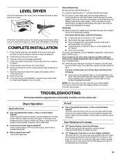
Installation Instructions
Page 15
.... Check that both fuses are intact and tight, or that the dryer is recommended to control the buildup of its first cycle. Be sure the vent is plugged into a grounded outlet. Wipe the dryer drum interior thoroughly with a qualified electrician. ■ Was a regular fuse used . For power supply cord installation, plug...
.... Check that both fuses are intact and tight, or that the dryer is recommended to control the buildup of its first cycle. Be sure the vent is plugged into a grounded outlet. Wipe the dryer drum interior thoroughly with a qualified electrician. ■ Was a regular fuse used . For power supply cord installation, plug...
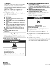
Installation Instructions
Page 16
... each load. See the Installation Instructions. ■ Are fabric softener sheets blocking the grille? See the Installation Instructions. ■ Is the exhaust vent diameter the correct size? The front of the dryer requires a minimum of 1" (25 mm) of dryer cycles requires temperatures above 45ºF ... operation of airspace, and, for details. ■ Select a Timed Dry heated cycle, and restart the dryer. Electric dryers use a plastic vent. If the message persists, have ventilation openings at the top and bottom of the dryer requires 5" (127 mm). Do not use two household...
... each load. See the Installation Instructions. ■ Are fabric softener sheets blocking the grille? See the Installation Instructions. ■ Is the exhaust vent diameter the correct size? The front of the dryer requires a minimum of 1" (25 mm) of dryer cycles requires temperatures above 45ºF ... operation of airspace, and, for details. ■ Select a Timed Dry heated cycle, and restart the dryer. Electric dryers use a plastic vent. If the message persists, have ventilation openings at the top and bottom of the dryer requires 5" (127 mm). Do not use two household...


