User Guide
Page 2
... First release for FAQ, technical guide, BIOS updates, driver updates, and other information: http://www.msi.com/index.php?func=service ◙ Contact our technical staff at: http://ocss.msi.com ii Alternatively, please try the following help resources for further guidance. ◙ Visit the MSI website for PCB 1.X Date August 2009 Technical Support If a problem arises with your system and...
... First release for FAQ, technical guide, BIOS updates, driver updates, and other information: http://www.msi.com/index.php?func=service ◙ Contact our technical staff at: http://ocss.msi.com ii Alternatively, please try the following help resources for further guidance. ◙ Visit the MSI website for PCB 1.X Date August 2009 Technical Support If a problem arises with your system and...
User Guide
Page 8
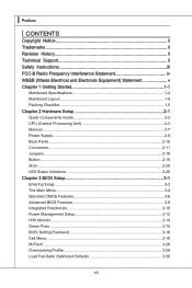
... Started 1-1 Mainboard Specifications 1-2 Mainboard Layout 1-4 Packing Checklist 1-5 Chapter 2 Hardware Setup 2-1 Quick Components Guide 2-2 CPU (Central Processing Unit 2-3 Memory 2-7 Power Supply 2-9 Back Panel 2-10 Connectors 2-11 Jumpers 2-18 Button 2-19 Slots 2-20 LED Status Indicators 2-26 Chapter 3 BIOS Setup 3-1 Entering Setup 3-2 The Main Menu 3-4 Standard CMOS Features 3-6 Advanced BIOS Features 3-8 Integrated Peripherals 3-10 Power Management Setup 3-12 H/W Monitor 3-14 Green Powr 3-15 BIOS Setting Password 3-16 Cell Menu 3-18 M-Flash 3-26 Overclocking...
... Started 1-1 Mainboard Specifications 1-2 Mainboard Layout 1-4 Packing Checklist 1-5 Chapter 2 Hardware Setup 2-1 Quick Components Guide 2-2 CPU (Central Processing Unit 2-3 Memory 2-7 Power Supply 2-9 Back Panel 2-10 Connectors 2-11 Jumpers 2-18 Button 2-19 Slots 2-20 LED Status Indicators 2-26 Chapter 3 BIOS Setup 3-1 Entering Setup 3-2 The Main Menu 3-4 Standard CMOS Features 3-6 Advanced BIOS Features 3-8 Integrated Peripherals 3-10 Power Management Setup 3-12 H/W Monitor 3-14 Green Powr 3-15 BIOS Setting Password 3-16 Cell Menu 3-18 M-Flash 3-26 Overclocking...
User Guide
Page 12
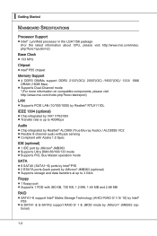
▍ Getting Started Mainboard Specifications Processor Support ■ Intel® Lynnfield processor in the LGA1156 package (For the latest information about CPU, please visit http://www.msi.com/index. tional) 1-2 php?func=cpuform2) Base Clock ■ 133 MHz Chipset ■ Intel® P55 chipset Memory Support ■ 4 DDR3 DIMMs support DDR3 2133*(OC)/ 2000*(OC) /1600*(OC)/ 1333/ 1066 DRAM (16GB Max) ■ Supports Dual-Channel mode *(For more information on compatible components, please visit...
▍ Getting Started Mainboard Specifications Processor Support ■ Intel® Lynnfield processor in the LGA1156 package (For the latest information about CPU, please visit http://www.msi.com/index. tional) 1-2 php?func=cpuform2) Base Clock ■ 133 MHz Chipset ■ Intel® P55 chipset Memory Support ■ 4 DDR3 DIMMs support DDR3 2133*(OC)/ 2000*(OC) /1600*(OC)/ 1333/ 1066 DRAM (16GB Max) ■ Supports Dual-Channel mode *(For more information on compatible components, please visit...
User Guide
Page 13
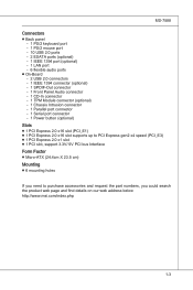
...) - 1 LAN port - 6 flexible audio ports ■ On-Board - 2 USB 2.0 connectors - 1 IEEE 1394 connector (optional) - 1 SPDIF-Out connector - 1 Front Panel Audio connector - 1 CD-In connector - 1 TPM Module connector (optional) - 1 Chassis Intrusion connector - 1 Parallel port connector - 1 Serial port connector - 1 Power button (optional) Slots ■ 1 PCI Express 2.0 x16 slot (PCI_E1) ■ 1 PCI Express 2.0 x16 slot supports up to PCI Express gen2 x4 speed (PCI_E3) ■ 1 PCI Express 2.0 x1 slot ■ 1 PCI slot, support 3.3V/ 5V PCI bus Interface Form Factor ■ Micro-ATX (24...
...) - 1 LAN port - 6 flexible audio ports ■ On-Board - 2 USB 2.0 connectors - 1 IEEE 1394 connector (optional) - 1 SPDIF-Out connector - 1 Front Panel Audio connector - 1 CD-In connector - 1 TPM Module connector (optional) - 1 Chassis Intrusion connector - 1 Parallel port connector - 1 Serial port connector - 1 Power button (optional) Slots ■ 1 PCI Express 2.0 x16 slot (PCI_E1) ■ 1 PCI Express 2.0 x16 slot supports up to PCI Express gen2 x4 speed (PCI_E3) ■ 1 PCI Express 2.0 x1 slot ■ 1 PCI slot, support 3.3V/ 5V PCI bus Interface Form Factor ■ Micro-ATX (24...
User Guide
Page 19
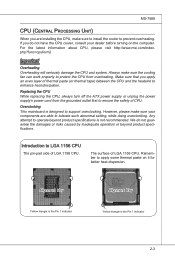
... beyond product specifications. Any attempt to support overclocking. Remember to tolerate such abnormal setting, while doing overclocking. For the latest information about CPU, please visit http://www.msi.com/index. Introduction to enhance heat dissipation. Alignment Key Yellow triangle is the Pin 1 indicator Alignment Key Yellow triangle is not recommended. Replacing the CPU While replacing the CPU, always turn off the ATX power supply or unplug the power supply's power cord...
... beyond product specifications. Any attempt to support overclocking. Remember to tolerate such abnormal setting, while doing overclocking. For the latest information about CPU, please visit http://www.msi.com/index. Introduction to enhance heat dissipation. Alignment Key Yellow triangle is the Pin 1 indicator Alignment Key Yellow triangle is not recommended. Replacing the CPU While replacing the CPU, always turn off the ATX power supply or unplug the power supply's power cord...

User Guide
Page 37
... section are for CrossFireXTM mode, make sure that these two graphics cards (refer to the picture below). With two cards installed, an CrossFireXTM Video Link cable is the ultimate multi-GPU performance gaming platform. Please note that you connect an adequate power supply to the power connector on the model you purchase. • If you have to enable the CrossFireXTM in BIOS by yourself. ATI...
... section are for CrossFireXTM mode, make sure that these two graphics cards (refer to the picture below). With two cards installed, an CrossFireXTM Video Link cable is the ultimate multi-GPU performance gaming platform. Please note that you connect an adequate power supply to the power connector on the model you purchase. • If you have to enable the CrossFireXTM in BIOS by yourself. ATI...

User Guide
Page 39
... to the following instructions. 1. Please note that the graphics card is required to connect the golden fingers on PCI Express x16 slots. To utilize this technology, the two GPU cards must be connected by an Multi-GPU Link card. Multi-GPU Link Card If you only need to connect a monitor to the picture below). Hence, you intend to use the Mult-GPU mode for better graphics performance, please...
... to the following instructions. 1. Please note that the graphics card is required to connect the golden fingers on PCI Express x16 slots. To utilize this technology, the two GPU cards must be connected by an Multi-GPU Link card. Multi-GPU Link Card If you only need to connect a monitor to the picture below). Hence, you intend to use the Mult-GPU mode for better graphics performance, please...

User Guide
Page 41
The PCI IRQ pins are hardware lines over which devices can send interrupt signals to the PCI bus pins as jumpers, switches or BIOS configuration. MS-7588 PCI (Peripheral Component Interconnect) Slot The PCI slot supports LAN card, SCSI card, USB card, and other add-on cards that comply with PCI specifications. 32-bit PCI Slot Important When adding or removing expansion cards, make sure that you unplug the power supply first. PCI Interrupt Request Routing The IRQ, acronym of interrupt request...
The PCI IRQ pins are hardware lines over which devices can send interrupt signals to the PCI bus pins as jumpers, switches or BIOS configuration. MS-7588 PCI (Peripheral Component Interconnect) Slot The PCI slot supports LAN card, SCSI card, USB card, and other add-on cards that comply with PCI specifications. 32-bit PCI Slot Important When adding or removing expansion cards, make sure that you unplug the power supply first. PCI Interrupt Request Routing The IRQ, acronym of interrupt request...

User Guide
Page 50
... BIOS uses to look for a boot device from which to load the operating system during the boot process. ▶ Boot From Other Device Setting the option to [Yes] allows the system to try to boot from accidental corruption by unauthorized users or computer viruses. To successfully update the BIOS, you will need to disable it against viruses. ▶ Full Screen Logo Display This item enables this function at boot...
... BIOS uses to look for a boot device from which to load the operating system during the boot process. ▶ Boot From Other Device Setting the option to [Yes] allows the system to try to boot from accidental corruption by unauthorized users or computer viruses. To successfully update the BIOS, you will need to disable it against viruses. ▶ Full Screen Logo Display This item enables this function at boot...

User Guide
Page 51
... guide, the system is able to run in APIC mode. To find out which MPS (Multi-Processor Specification) version to be used to [On] will turn on the Num Lock key when the system is powered on . For better PCI performance, you to select which version to select the MPS version supported by your primary graphics adapter. ▶ PCI Latency Timer This item controls how long each PCI device...
... guide, the system is able to run in APIC mode. To find out which MPS (Multi-Processor Specification) version to be used to [On] will turn on the Num Lock key when the system is powered on . For better PCI performance, you to select which version to select the MPS version supported by your primary graphics adapter. ▶ PCI Latency Timer This item controls how long each PCI device...

User Guide
Page 52
...Onboard LAN Controller This setting allows you to enable/disable the onboard LAN controller. ▶ LAN Option ROM This item is used to decide whether to invoke the Boot ROM of the onboard LAN. ▶ Onboard IEEE1394 Controller This item allows you to enable/disable the onboard IEEE1394 controller. ▶ Extra RAID/ IDE Controller (optional) This item allows you to enable/disable the onboard extra RAID/ IDE controller. ▶ RAID Mode This item is used to select mode for extra RAID connector. ▶ HD Audio Controller This setting is used to enable/disable the onboard audio controller...
...Onboard LAN Controller This setting allows you to enable/disable the onboard LAN controller. ▶ LAN Option ROM This item is used to decide whether to invoke the Boot ROM of the onboard LAN. ▶ Onboard IEEE1394 Controller This item allows you to enable/disable the onboard IEEE1394 controller. ▶ Extra RAID/ IDE Controller (optional) This item allows you to enable/disable the onboard extra RAID/ IDE controller. ▶ RAID Mode This item is used to select mode for extra RAID connector. ▶ HD Audio Controller This setting is used to enable/disable the onboard audio controller...
User Guide
Page 53
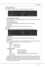
... ECP mode only. MS-7588 ▶ On-Chip ATA Devices Press to enter the sub-menu and the following screen appears: ▶ PCI IDE BusMaster (optional) This item allows you to enable/ disable BIOS to used to select mode for reading/ writing to IDE drives. ▶ On-Chip SATA Controller This item allows users to enable or disable the on-chip SATA controller. ▶ RAID Mode This item is a built-in parallel port on the on -chip SATA connectors. ▶ I /O chipset that...
... ECP mode only. MS-7588 ▶ On-Chip ATA Devices Press to enter the sub-menu and the following screen appears: ▶ PCI IDE BusMaster (optional) This item allows you to enable/ disable BIOS to used to select mode for reading/ writing to IDE drives. ▶ On-Chip SATA Controller This item allows users to enable or disable the on-chip SATA controller. ▶ RAID Mode This item is a built-in parallel port on the on -chip SATA connectors. ▶ I /O chipset that...

User Guide
Page 54
... in memory will be used to save energy. ▍ BIOS Setup Power Management Setup Important S3-related functions described in this section are : [S1] The S1 sleep mode is lost (CPU or chipset) and hardware maintains all sys- If your operating system supports ACPI, such as Windows 98SE/ 2000/ ME/ XP, select [Enabled]. ▶ ACPI Standby State This item specifies the power saving modes for ACPI function. Settings are...
... in memory will be used to save energy. ▍ BIOS Setup Power Management Setup Important S3-related functions described in this section are : [S1] The S1 sleep mode is lost (CPU or chipset) and hardware maintains all sys- If your operating system supports ACPI, such as Windows 98SE/ 2000/ ME/ XP, select [Enabled]. ▶ ACPI Standby State This item specifies the power saving modes for ACPI function. Settings are...

User Guide
Page 56
... can control the CPU fan speed automatically depending on the current temperature to [Reset]. It provides several sections to speed up for the SYSFAN1/ 2. ▶ PC Health Status ▶ CPU/ System Temperature, CPU FAN/ SYS FAN 1/ 2 Speed, CPU Vcore, 3.3V, 5V, 12V These items display the current status of all of the monitored hardware devices/components such as CPU voltage, temperatures and all fans' speeds. 3-14 ▍ BIOS Setup H/W Monitor ▶ Chassis Intrusion The field enables or disables...
... can control the CPU fan speed automatically depending on the current temperature to [Reset]. It provides several sections to speed up for the SYSFAN1/ 2. ▶ PC Health Status ▶ CPU/ System Temperature, CPU FAN/ SYS FAN 1/ 2 Speed, CPU Vcore, 3.3V, 5V, 12V These items display the current status of all of the monitored hardware devices/components such as CPU voltage, temperatures and all fans' speeds. 3-14 ▍ BIOS Setup H/W Monitor ▶ Chassis Intrusion The field enables or disables...
User Guide
Page 65
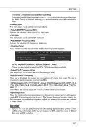
... you do not have any EMI problem, leave the setting at [Disabled] for EMI reduction. 3-23 But if you to set the following screen appears. ▶ CPU Amplitude Control/ PCI Express Amplitude Control These items are used to set to [Enabled], the system will remove (turn off) clocks from empty PCI slot to minimize the electromagnetic interference (EMI). ▶ CPU Voltage(V)/ CPU VTT (V)/ PCH 1.8V (V)/ DRAM Voltage (V)/ DDR_VREF_CA_A (V)/ / DDR_VREF_CA_B (V)/ DDR_VREF_DA_A (V)/ / DDR_VREF_DA_B (V)/ PCH 1.05V...
... you do not have any EMI problem, leave the setting at [Disabled] for EMI reduction. 3-23 But if you to set the following screen appears. ▶ CPU Amplitude Control/ PCI Express Amplitude Control These items are used to set to [Enabled], the system will remove (turn off) clocks from empty PCI slot to minimize the electromagnetic interference (EMI). ▶ CPU Voltage(V)/ CPU VTT (V)/ PCH 1.8V (V)/ DRAM Voltage (V)/ DDR_VREF_CA_A (V)/ / DDR_VREF_CA_B (V)/ DDR_VREF_DA_A (V)/ / DDR_VREF_DA_B (V)/ PCH 1.05V...

User Guide
Page 70
... using [ROM] as default name. ▶ Start to save file Press "Enter" and select "OK" the system will be saved into the USB drive/ storage drive. Note: it to USB drive/ storage drive. ▶ Save File to Selected Device Please setup a specific folder in specific USB drive/ storage drive to save BIOS file from the USB/ Storage (FAT/32 format only) drive. == Backup BIOS to USB drive == The following fields are used to read the onboard BIOS ROM data, and save the onboard ROM chip data to [Boot] or [BIOS Update...
... using [ROM] as default name. ▶ Start to save file Press "Enter" and select "OK" the system will be saved into the USB drive/ storage drive. Note: it to USB drive/ storage drive. ▶ Save File to Selected Device Please setup a specific folder in specific USB drive/ storage drive to save BIOS file from the USB/ Storage (FAT/32 format only) drive. == Backup BIOS to USB drive == The following fields are used to read the onboard BIOS ROM data, and save the onboard ROM chip data to [Boot] or [BIOS Update...

User Guide
Page 106
.... All the information/ volumes/ pictures listed in unison. Spreading the hard drive I/O load across independent channels greatly improves I/O performance. Intel® Rapid Recover Technology utilizes RAID 1 functionality to copy data from the illustrations in excellent performance and good fault tolerance. SATA hard drives deliver blistering transfer speeds up to a designated Recovery drive. Serial ATA uses long, thin cables, making it easier to the size of RAID. Supports Hot-plug-n-play feature. 3. Data handling...
.... All the information/ volumes/ pictures listed in unison. Spreading the hard drive I/O load across independent channels greatly improves I/O performance. Intel® Rapid Recover Technology utilizes RAID 1 functionality to copy data from the illustrations in excellent performance and good fault tolerance. SATA hard drives deliver blistering transfer speeds up to a designated Recovery drive. Serial ATA uses long, thin cables, making it easier to the size of RAID. Supports Hot-plug-n-play feature. 3. Data handling...
User Guide
Page 107
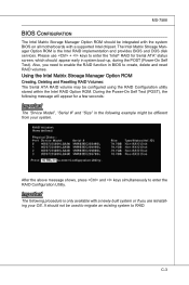
...: Important The "Drvice Model", "Serial #" and "Size" in system boot-up, during the POST (Power-On Self Test). MS-7588 BIOS Configuration The Intel Matrix Storage Manager Option ROM should be used to migrate an existing system to create, delete and reset RAID volumes. The Intel Matrix Stroage Manager Option ROM is only available with a supported Intel chipset. Important The following example might be configured using the RAID Configuration utility stored within the Intel RAID Option ROM. Please use + keys to enter the RAID Configuration Utility.
...: Important The "Drvice Model", "Serial #" and "Size" in system boot-up, during the POST (Power-On Self Test). MS-7588 BIOS Configuration The Intel Matrix Storage Manager Option ROM should be used to migrate an existing system to create, delete and reset RAID volumes. The Intel Matrix Stroage Manager Option ROM is only available with a supported Intel chipset. Important The following example might be configured using the RAID Configuration utility stored within the Intel RAID Option ROM. Please use + keys to enter the RAID Configuration Utility.
User Guide
Page 114
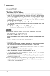
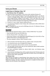
... screen should be prompted to insert a floppy disk containing the Intel® RAID driver into the DVD-ROM drive. • Click the "Browse DVD" on "Load Driver" button to install a third party SCSI or RAID driver. 5. You have selected the Intel® RAID controller. C-10 Important Please follow the instruction below to make an "Intel® RAID Driver" for Intel® PCH RAID Controller is done. 4. You should confirm that you can use the USB floppy drive only. ▍ Intel SATA RAID Installing Driver Install Driver in \\RAID\ Intel...
... screen should be prompted to insert a floppy disk containing the Intel® RAID driver into the DVD-ROM drive. • Click the "Browse DVD" on "Load Driver" button to install a third party SCSI or RAID driver. 5. You have selected the Intel® RAID controller. C-10 Important Please follow the instruction below to make an "Intel® RAID Driver" for Intel® PCH RAID Controller is done. 4. You should confirm that you can use the USB floppy drive only. ▍ Intel SATA RAID Installing Driver Install Driver in \\RAID\ Intel...
User Guide
Page 143
... storage devices installed in your system". And then, follow the instruction below to supply the driver. Windows setup will need to insert a floppy disk containing the JMicron RAID driver into the DVD-ROM drive. • Click the "Browse DVD" on the "Load Driver" button to complete the RAID drive installation and the Windows Vista installation. Press the "S" key to continue. 8. counter a message stating, "Setup could not determine the type of available SCSI Adapters. 6. If this is the case...
... storage devices installed in your system". And then, follow the instruction below to supply the driver. Windows setup will need to insert a floppy disk containing the JMicron RAID driver into the DVD-ROM drive. • Click the "Browse DVD" on the "Load Driver" button to complete the RAID drive installation and the Windows Vista installation. Press the "S" key to continue. 8. counter a message stating, "Setup could not determine the type of available SCSI Adapters. 6. If this is the case...


