
User Guide
Page 2
... of M ICRO-STAR INTERNATIONAL. AMD, Athlon™, Athlon™ XP, Thoroughbred™, and Duron™ are registered trademarks of AMD Corporation. Intel® and Pentium® are registered trademarks of Intel Corporation. PS/2 and OS®/2 are registered trademarks or trademarks of Microsoft Corporation. Visit the MSI website for FAQ, technical guide, BIOS updates, driver updates, and other countries...
... of M ICRO-STAR INTERNATIONAL. AMD, Athlon™, Athlon™ XP, Thoroughbred™, and Duron™ are registered trademarks of AMD Corporation. Intel® and Pentium® are registered trademarks of Intel Corporation. PS/2 and OS®/2 are registered trademarks or trademarks of Microsoft Corporation. Visit the MSI website for FAQ, technical guide, BIOS updates, driver updates, and other countries...

User Guide
Page 3
... NOT LEAVETHIS EQUIPMENT INANENVIRONMENT UNCONDITIONED, STORAGE TEMPERATURE ABOVE 600 C (1400F), IT MAYDAMAGE THE EQUIPMENT. ment from humidity. 4. fore connecting the equipment to User's Manual. † The equipment has dropped and damaged. † The equipment has obvious sign of expl os i on card or module. 9. Always Unplug the Power Cord before setting it work well or you can not step...
... NOT LEAVETHIS EQUIPMENT INANENVIRONMENT UNCONDITIONED, STORAGE TEMPERATURE ABOVE 600 C (1400F), IT MAYDAMAGE THE EQUIPMENT. ment from humidity. 4. fore connecting the equipment to User's Manual. † The equipment has dropped and damaged. † The equipment has obvious sign of expl os i on card or module. 9. Always Unplug the Power Cord before setting it work well or you can not step...

User Guide
Page 4
... user's authority to Part 15 of the FCC Rules. Notice 2 Shielded interface cables and A.C. This equipment generates, uses and can be used in a residential installation. FCC-B Radio Frequency Interference Statement T h is eq uip men t h as been tested and found to comply with the limits for a Class B digital device, pursuant to operate the equipment. Micro-Star International MS-7519 This device...
... user's authority to Part 15 of the FCC Rules. Notice 2 Shielded interface cables and A.C. This equipment generates, uses and can be used in a residential installation. FCC-B Radio Frequency Interference Statement T h is eq uip men t h as been tested and found to comply with the limits for a Class B digital device, pursuant to operate the equipment. Micro-Star International MS-7519 This device...

User Guide
Page 8
... Tradema rks ...ii Revision History ...ii Technical Support ...ii Safety Instructions iii FCC-B Radio Frequency Interference Statement iv WEEE (Waste Electrical and Electronic Equipment) Statement v English ...En-1 Specifications ...En-2 Central Processing Unit: CPU En-5 Memory ...En-7 Connectors, Jumpers, Slots En-9 Back Panel ...En-15 BIOS Setup ...En-17 Software Information En-21 Deutsch ...De-1 Spezifikationen De-2 Hauptprozessor: CPU De-5 Speicher ...De-7 Anschlüsse...
... Tradema rks ...ii Revision History ...ii Technical Support ...ii Safety Instructions iii FCC-B Radio Frequency Interference Statement iv WEEE (Waste Electrical and Electronic Equipment) Statement v English ...En-1 Specifications ...En-2 Central Processing Unit: CPU En-5 Memory ...En-7 Connectors, Jumpers, Slots En-9 Back Panel ...En-15 BIOS Setup ...En-17 Software Information En-21 Deutsch ...De-1 Spezifikationen De-2 Hauptprozessor: CPU De-5 Speicher ...De-7 Anschlüsse...

User Guide
Page 10
....php?func=testreport) LAN - Supports PIO, Bus Master operation mode SATA - 6 SATAII ports by Realtek 8111C Audio - Supports 1394 by Realtek® ALC888 - Intel® Core 2 Extreme, Core 2 Quad, Core 2 Duo, Pentium Dual- Chip integrated by JMicron JMB381 En-2 Meets Microsoft Vista Premium spec IDE - 1 IDE port by JMicron JMB 368 - Supports storage and data transfers at up to 3 Gb/s 1394 (optional) - Flexible 8-channel audio with Azalia 1.0 Spec - MS-7519 Mainboard Specifications Processor Support - Supports Ultra DMA 66...
....php?func=testreport) LAN - Supports PIO, Bus Master operation mode SATA - 6 SATAII ports by Realtek 8111C Audio - Supports 1394 by Realtek® ALC888 - Intel® Core 2 Extreme, Core 2 Quad, Core 2 Duo, Pentium Dual- Chip integrated by JMicron JMB381 En-2 Meets Microsoft Vista Premium spec IDE - 1 IDE port by JMicron JMB 368 - Supports storage and data transfers at up to 3 Gb/s 1394 (optional) - Flexible 8-channel audio with Azalia 1.0 Spec - MS-7519 Mainboard Specifications Processor Support - Supports Ultra DMA 66...
User Guide
Page 11
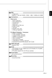
.../2 keyboard port - 1 Parallel port - 1 Serial port - 1 VGA port (for G45 only) - 4 USB 2.0 Ports - 1 LAN jack - 6 flexible audio jacks - 1 1394 port (optional) On-Board Pinheaders / Connectors - 4 USB 2.0 pinheaders - 1 1394 pinheader (optional) - 1 chassis intrusion connector - 1 SPDIF-out pinheader - 1 CD-in connector - 1 front audio pinheader - 1 TPM Module connector (optional) - 2 Hardware Overclock FSB jumpers (JB1 & JB2) TPM (optional) - Supports TPM Slots - 1 PCI Express x16 slot, supports up to PCI Express 2.0 x16 speed - 2 PCI Express x1 slots - 3 PCI slots, support 3.3V/ 5V PCI bus...
.../2 keyboard port - 1 Parallel port - 1 Serial port - 1 VGA port (for G45 only) - 4 USB 2.0 Ports - 1 LAN jack - 6 flexible audio jacks - 1 1394 port (optional) On-Board Pinheaders / Connectors - 4 USB 2.0 pinheaders - 1 1394 pinheader (optional) - 1 chassis intrusion connector - 1 SPDIF-out pinheader - 1 CD-in connector - 1 front audio pinheader - 1 TPM Module connector (optional) - 2 Hardware Overclock FSB jumpers (JB1 & JB2) TPM (optional) - Supports TPM Slots - 1 PCI Express x16 slot, supports up to PCI Express 2.0 x16 speed - 2 PCI Express x1 slots - 3 PCI slots, support 3.3V/ 5V PCI bus...

User Guide
Page 13
... will seriously damage the CPU and system. Any attempt to tolerate such abnormal setting, while doing overclocking. Always make sure your dealer before turning on the com puter. Replacing the CPU While replacing the CPU, always turn off the ATX power supply or unplug the power supply's power cord from overheating. English Central Processing Unit: CPU The m ainboard supports Intel® processor. En-5 The mainboard uses a CPU socket called Socket 775 for easy CPU installation.
... will seriously damage the CPU and system. Any attempt to tolerate such abnormal setting, while doing overclocking. Always make sure your dealer before turning on the com puter. Replacing the CPU While replacing the CPU, always turn off the ATX power supply or unplug the power supply's power cord from overheating. English Central Processing Unit: CPU The m ainboard supports Intel® processor. En-5 The mainboard uses a CPU socket called Socket 775 for easy CPU installation.

User Guide
Page 14
... socket pin. 2. Mainboard photos shown in BIOS. 2. MS-7519 Mainboard CPU & Cooler Installation Procedures for correct mating, put down the load lever lightly onto the load plate, and then secure the lever with the hook under retention tab. 10.Align the holes on the edge of socket reveal. 4. Before you purchase. The pins of the CPU base. Visually inspect if the CPU is not installed...
... socket pin. 2. Mainboard photos shown in BIOS. 2. MS-7519 Mainboard CPU & Cooler Installation Procedures for correct mating, put down the load lever lightly onto the load plate, and then secure the lever with the hook under retention tab. 10.Align the holes on the edge of socket reveal. 4. Before you purchase. The pins of the CPU base. Visually inspect if the CPU is not installed...

User Guide
Page 15
... on compatible components, please visit http://global.msi.com. tw/index.php?func=testreport 64x2=128 pin 56x2=112 pin Dual-Channel Memory Population Rules In Dual-Channel mode, the memory modules can enhance the system performance. In Dual-Channel mode, make sure that you install memory modules of the same type and density in the DDR2 DIMM slots. - Please refer to the following illustrations for installing memory modules. En-7 Enabling Dual-Channel mode...
... on compatible components, please visit http://global.msi.com. tw/index.php?func=testreport 64x2=128 pin 56x2=112 pin Dual-Channel Memory Population Rules In Dual-Channel mode, the memory modules can enhance the system performance. In Dual-Channel mode, make sure that you install memory modules of the same type and density in the DDR2 DIMM slots. - Please refer to the following illustrations for installing memory modules. En-7 Enabling Dual-Channel mode...

User Guide
Page 17
... floppy disk drive. You can install Dual Core Center utility that the red wire is the positive and should be connected to the +12V, the black wire is Ground and should be connected to Master/ Slave mode by the vendors for proper CPU cooling fan. 2. Refer to the recommended CPU fans at processor's official website or consult the vendors for jumper setting instructions. En-9 The CPU FAN supports Smart FAN function. Control SENSOR +1 2V GND English Connectors, Jumpers, Slots Fan Power Connectors...
... floppy disk drive. You can install Dual Core Center utility that the red wire is the positive and should be connected to the +12V, the black wire is Ground and should be connected to Master/ Slave mode by the vendors for proper CPU cooling fan. 2. Refer to the recommended CPU fans at processor's official website or consult the vendors for jumper setting instructions. En-9 The CPU FAN supports Smart FAN function. Control SENSOR +1 2V GND English Connectors, Jumpers, Slots Fan Power Connectors...
User Guide
Page 18
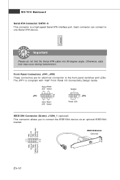
... 1 9 IEEE1394 Bracket (Optional) TPA+ Ground TPB+ Cable power Key (no pin) En-10 Each connector can connect to the front panel switches and LEDs. Otherwise, data loss may occur during transmission. Power Power LED Switch Speaker JFP1 2 1 10 9 HDD Reset LED Switch 2 1 8 7 JFP2 Power LED IEEE1394 Connector (Green): J1394_1 (optional) This connector allows you to connect the IEEE1394 device via an optional IEEE1394 brac ket . MS-7519 Mainboard Serial ATA Connector: SATA1~6 This connector is compliant with Intel® Front Panel I/O Connectivity Design Guide.
... 1 9 IEEE1394 Bracket (Optional) TPA+ Ground TPB+ Cable power Key (no pin) En-10 Each connector can connect to the front panel switches and LEDs. Otherwise, data loss may occur during transmission. Power Power LED Switch Speaker JFP1 2 1 10 9 HDD Reset LED Switch 2 1 8 7 JFP2 Power LED IEEE1394 Connector (Green): J1394_1 (optional) This connector allows you to connect the IEEE1394 device via an optional IEEE1394 brac ket . MS-7519 Mainboard Serial ATA Connector: SATA1~6 This connector is compliant with Intel® Front Panel I/O Connectivity Design Guide.
User Guide
Page 19
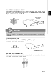
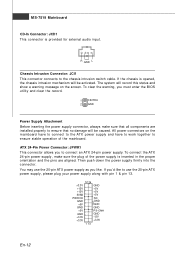
... SPDIF_out VCC GND SPDIF Bracket (Optional) Front Panel Audio Connector: JAUD1 This connector allows you to connect S/PDIF (Sony & Philips Digital Interconnect Format) interface for connecting high-speed USB interface peripherals such as USB HDD, digital cameras, MP3 players, printers, modems and the like. 10 9 USBOC Key (no pin) GND GND USB1+ USB0+ USB1- S/PDIF-Out Connector: JSP1 This connector is used to connect the front panel audio and is ideal...
... SPDIF_out VCC GND SPDIF Bracket (Optional) Front Panel Audio Connector: JAUD1 This connector allows you to connect S/PDIF (Sony & Philips Digital Interconnect Format) interface for connecting high-speed USB interface peripherals such as USB HDD, digital cameras, MP3 players, printers, modems and the like. 10 9 USBOC Key (no pin) GND GND USB1+ USB0+ USB1- S/PDIF-Out Connector: JSP1 This connector is used to connect the front panel audio and is ideal...
User Guide
Page 20
... the screen. The system will be caused. R GND L Chassis Intrusion Connector: JCI1 This connector connects to ensure stable operation of the power supply is provided for external audio input. If you must enter the BIOS utility and clear the record. 1 CINTRU 2 GND Power Supply Attachment Before inserting the power supply connector, always make sure the plug of the m ainboard. ATX 24-Pin Power Connector: JPWR1 This connector allows you like to use the 20-pin ATX power supply...
... the screen. The system will be caused. R GND L Chassis Intrusion Connector: JCI1 This connector connects to ensure stable operation of the power supply is provided for external audio input. If you must enter the BIOS utility and clear the record. 1 CINTRU 2 GND Power Supply Attachment Before inserting the power supply connector, always make sure the plug of the m ainboard. ATX 24-Pin Power Connector: JPWR1 This connector allows you like to use the 20-pin ATX power supply...

User Guide
Page 21
... 2 GND GND Key(no pin) VCC5 SIRQ VCC3 3Vdual / 3V_STB Hardware Overclock FSB Jumpers: JB1, JB2 (optional) You can overclock the FSB to a TPM (Trusted Platform Module) module (optional). English ATX 12V Power Connector (2x2-Pin): JPWR2 This 12V power connector is used to provide power to the CPU. 21 GND GND 12V 12V 43 TPM Module Connector: JTPM1 (optional) This connector connects to increase the processor frequency by changing the jumpers JB1 and...
... 2 GND GND Key(no pin) VCC5 SIRQ VCC3 3Vdual / 3V_STB Hardware Overclock FSB Jumpers: JB1, JB2 (optional) You can overclock the FSB to a TPM (Trusted Platform Module) module (optional). English ATX 12V Power Connector (2x2-Pin): JPWR2 This 12V power connector is used to provide power to the CPU. 21 GND GND 12V 12V 43 TPM Module Connector: JTPM1 (optional) This connector connects to increase the processor frequency by changing the jumpers JB1 and...

User Guide
Page 22
... card, USB card, and other add-on ; If you unplug the power supply first. Avoid clearing the CMOS while the system is off. Important When adding or removing expansion cards, make sure that comply with PCI specifications. PCI Express Slot (x16/ x1) The PCI Express slot supports the PCI Express interface expansion card. W ith the CMOS RAM, the system can clear CMOS by shorting 2-3 pin while the system is on cards that you want to clear the system configuration, set the jumper...
... card, USB card, and other add-on ; If you unplug the power supply first. Avoid clearing the CMOS while the system is off. Important When adding or removing expansion cards, make sure that comply with PCI specifications. PCI Express Slot (x16/ x1) The PCI Express slot supports the PCI Express interface expansion card. W ith the CMOS RAM, the system can clear CMOS by shorting 2-3 pin while the system is on cards that you want to clear the system configuration, set the jumper...

User Guide
Page 25
....0 051508 where: 1st digit refers to BIOS maker as A = AMI, W = AWARD, and P = PHOENIX. 2nd - 5th digit refers to the model number. 6th refers to the Chipset vender as A = AMD, I = Intel, V = VIA, N = Nvidia, U = ULi. 7th - 8th digit refers to the customer as MS = all standard customers. Important 1.The items under continuous update for optimum use. It is the BIOS version.
....0 051508 where: 1st digit refers to BIOS maker as A = AMI, W = AWARD, and P = PHOENIX. 2nd - 5th digit refers to the model number. 6th refers to the Chipset vender as A = AMD, I = Intel, V = VIA, N = Nvidia, U = ULi. 7th - 8th digit refers to the customer as MS = all standard customers. Important 1.The items under continuous update for optimum use. It is the BIOS version.
User Guide
Page 26
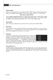
... start POST (Power On Self Test) process. En-18 W hen the m essage below appears on the screen, press key to select the item . General Help The BIOS setup program provides a General Help screen. You can use control keys (↑↓ ) to highlight the field and press to use the control keys to enter values and move from any menu by simply pressing . The Help screen lists the appropriate keys...
... start POST (Power On Self Test) process. En-18 W hen the m essage below appears on the screen, press key to select the item . General Help The BIOS setup program provides a General Help screen. You can use control keys (↑↓ ) to highlight the field and press to use the control keys to enter values and move from any menu by simply pressing . The Help screen lists the appropriate keys...

User Guide
Page 27
...-menu. Power Management Setup Use this menu to load the default values set by the mainboard manufacturer specifically for frequency/voltage control and overclocking. BIOS Setting Password Use this menu to setup the item s of the m ai nboard. Advanced BIOS Features Use this menu for stable system perform ance. Standard CMOS Features Use this menu to specify your PC health status. Load Fail-Safe Defaults Use this menu to CMOS and exit setup. The Main Menu allows you enter AMI® or AW ARD® BIOS CMOS Setup Utility, the Main Menu...
...-menu. Power Management Setup Use this menu to load the default values set by the mainboard manufacturer specifically for frequency/voltage control and overclocking. BIOS Setting Password Use this menu to setup the item s of the m ai nboard. Advanced BIOS Features Use this menu for stable system perform ance. Standard CMOS Features Use this menu to specify your PC health status. Load Fail-Safe Defaults Use this menu to CMOS and exit setup. The Main Menu allows you enter AMI® or AW ARD® BIOS CMOS Setup Utility, the Main Menu...

User Guide
Page 28
... below for general use only. Load Optimized Defaults : Use control keys (↑↓ ) to highlight the Load Optimized Defaults field and press , a message as below appears: Select [Ok] and press Enter to enter the Standard CMOS Features-m enu. Important The configuration above are for general use . 1. MS-7519 Mainboard W hen enter the BIOS Setup utility, follow the processes below appears: Select [Ok] and press Enter to load the default settings for optimal...
... below for general use only. Load Optimized Defaults : Use control keys (↑↓ ) to highlight the Load Optimized Defaults field and press , a message as below appears: Select [Ok] and press Enter to enter the Standard CMOS Features-m enu. Important The configuration above are for general use . 1. MS-7519 Mainboard W hen enter the BIOS Setup utility, follow the processes below appears: Select [Ok] and press Enter to load the default settings for optimal...

User Guide
Page 29
... the device. The Driver/Utility CD contains the: Driver menu - The Utility menu shows the software applications that is included in the mainboard package, and place it into the CD-ROM driver. English Software Information Take out the Driver/Utility CD that the mainboard supports. The W ebSite menu shows the necessary websites. Utility m enu - The installation will auto-run, sim ply click the driver or utility and follow the pop-up screen to...
... the device. The Driver/Utility CD contains the: Driver menu - The Utility menu shows the software applications that is included in the mainboard package, and place it into the CD-ROM driver. English Software Information Take out the Driver/Utility CD that the mainboard supports. The W ebSite menu shows the necessary websites. Utility m enu - The installation will auto-run, sim ply click the driver or utility and follow the pop-up screen to...


