User Guide
Page 2
... or trademarks of NVIDIA Corporation in the United States and/or other information: http://www.msi.com.tw/program/service/faq/ faq/esc_faq_list.php Contact our technical staff at: http://support.msi.com.tw/ ii AMD, Athlon™, Athlon™ XP, Thoroughbred™, and Duron...First release for PCB 1.X Date March 2007 Technical Support If a problem arises with your place of purchase or local distributor. Visit the MSI website for further guidance. Intel® and Pentium® are registered trademarks of International Business Machines Corporation. AMI® is the intellectual ...
... or trademarks of NVIDIA Corporation in the United States and/or other information: http://www.msi.com.tw/program/service/faq/ faq/esc_faq_list.php Contact our technical staff at: http://support.msi.com.tw/ ii AMD, Athlon™, Athlon™ XP, Thoroughbred™, and Duron...First release for PCB 1.X Date March 2007 Technical Support If a problem arises with your place of purchase or local distributor. Visit the MSI website for further guidance. Intel® and Pentium® are registered trademarks of International Business Machines Corporation. AMI® is the intellectual ...
User Guide
Page 3
Keep this User's Manual for air convection hence protects the equip- Lay this equipment away from overheating. Place the power cord such a way that could damage or cause electrical s h oc k . 11. Replac e only with the same or equivalent type rec ommended by service personnel: † The power cord or plug is damaged. † Liquid has penetrated into the opening that people can not get the equipment checked by the m an uf ac t ur er. Safety Instructions 1. The openings on card or module. 9. Make sure the voltage of expl os i on the equipment should be - fore ...
Keep this User's Manual for air convection hence protects the equip- Lay this equipment away from overheating. Place the power cord such a way that could damage or cause electrical s h oc k . 11. Replac e only with the same or equivalent type rec ommended by service personnel: † The power cord or plug is damaged. † Liquid has penetrated into the opening that people can not get the equipment checked by the m an uf ac t ur er. Safety Instructions 1. The openings on card or module. 9. Make sure the voltage of expl os i on the equipment should be - fore ...
User Guide
Page 4
These limits are designed to the following two conditions: (1) this device may not cause harmful interference, and (2) this equipment does cause harmful interference to radio or television reception, which the receiver is connected. † Consult the dealer or an experienced radio/television technician for help. However, there is no guarantee that to comply with the emission limits. Operation is subject to provide reasonable protection against harmful interference in order to which can radiate radio frequency energy and, if not installed and used in a residential installation...
These limits are designed to the following two conditions: (1) this device may not cause harmful interference, and (2) this equipment does cause harmful interference to radio or television reception, which the receiver is connected. † Consult the dealer or an experienced radio/television technician for help. However, there is no guarantee that to comply with the emission limits. Operation is subject to provide reasonable protection against harmful interference in order to which can radiate radio frequency energy and, if not installed and used in a residential installation...

User Guide
Page 5
WEEE (Waste Electrical and Electronic Equipment) Statement v
WEEE (Waste Electrical and Electronic Equipment) Statement v
User Guide
Page 8
CONTENTS Copyright Notice ...ii Trademarks ...ii Revision History ...ii Technical Support ...ii Safety Instructions ...iii FCC-B Radio Frequency Interference Statement iv W EEE (Waste Electrical and Electronic Equipment) Statement v Chapter 1 Getting Started 1-1 Mainboard Specifications 1-2 Mainboard Layout 1-4 Packing Checklist 1-5 Chapter 2 Hardware Setup 2-1 Quick Components Guide 2-2 CPU (Central Processing Unit 2-3 Memory ...2-7 Power Supply ...2-9 Back Panel ...2-10 Connectors ...2-12 Jumper ...2-19 Slots ...2-20 Chapter 3 BIOS Setup 3-1 Entering Setup ...3-2 The Main Menu ...
CONTENTS Copyright Notice ...ii Trademarks ...ii Revision History ...ii Technical Support ...ii Safety Instructions ...iii FCC-B Radio Frequency Interference Statement iv W EEE (Waste Electrical and Electronic Equipment) Statement v Chapter 1 Getting Started 1-1 Mainboard Specifications 1-2 Mainboard Layout 1-4 Packing Checklist 1-5 Chapter 2 Hardware Setup 2-1 Quick Components Guide 2-2 CPU (Central Processing Unit 2-3 Memory ...2-7 Power Supply ...2-9 Back Panel ...2-10 Connectors ...2-12 Jumper ...2-19 Slots ...2-20 Chapter 3 BIOS Setup 3-1 Entering Setup ...3-2 The Main Menu ...

User Guide
Page 9
Clock ...A-6 Voltage ...A-7 FAN Speed ...A-8 Temperature ...A-9 User Profile ...A-10 Appendix B Realtek ALC888 Audio B-1 Installing the Realtek Audio Driver B-2 Software Configuration B-4 Hardware Setup B-19 ix
Clock ...A-6 Voltage ...A-7 FAN Speed ...A-8 Temperature ...A-9 User Profile ...A-10 Appendix B Realtek ALC888 Audio B-1 Installing the Realtek Audio Driver B-2 Software Configuration B-4 Hardware Setup B-19 ix
User Guide
Page 10
Getting Started Chapter 1 Getting Started Thank you for optimal system efficiency. Designed to fit the advanced Intel® Core 2 Extreme, Core 2 Quad, Core 2 Duo, Pentium and Celeron processor, the P35 Neo Combo/ G33 Neo Combo Series deliver a high performance and professional desktop platform solution. 1-1 The P35 Neo Combo/ G33 Neo Combo Series mainboards are based on Intel® P35/G33 & ICH9/ICH9R chipsets for choosing the P35 Neo Combo/ G33 Neo Combo Series (MS-7365 v1.X) ATX mainboard.
Getting Started Chapter 1 Getting Started Thank you for optimal system efficiency. Designed to fit the advanced Intel® Core 2 Extreme, Core 2 Quad, Core 2 Duo, Pentium and Celeron processor, the P35 Neo Combo/ G33 Neo Combo Series deliver a high performance and professional desktop platform solution. 1-1 The P35 Neo Combo/ G33 Neo Combo Series mainboards are based on Intel® P35/G33 & ICH9/ICH9R chipsets for choosing the P35 Neo Combo/ G33 Neo Combo Series (MS-7365 v1.X) ATX mainboard.
User Guide
Page 11
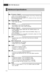
...2 Extreme, Core 2 Quad, Core 2 Duo, Pentium and Celeron in the LGA775 package (For the latest information about CPU, please visit http://www.msi. Transfer rate is controlled by Realtek RTL8111B IEEE 1394(optional) - South Bridge: Intel® ICH9/ ICH9R (optional) Memory Support - 2 DDR2 DIMMs... 300 MB/s RAID - ECC/ 4GB Max) (For more information on compatible components, please visit http:/ /www.msi.com.tw/testreport.htm) LAN - Supports 7.1 channels audio out - North Bridge: Intel® P35/ G33 (optional) - Supports Ultra DMA 66/100/133, PIO & Bus Master operation m ode SATA - 4...
...2 Extreme, Core 2 Quad, Core 2 Duo, Pentium and Celeron in the LGA775 package (For the latest information about CPU, please visit http://www.msi. Transfer rate is controlled by Realtek RTL8111B IEEE 1394(optional) - South Bridge: Intel® ICH9/ ICH9R (optional) Memory Support - 2 DDR2 DIMMs... 300 MB/s RAID - ECC/ 4GB Max) (For more information on compatible components, please visit http:/ /www.msi.com.tw/testreport.htm) LAN - Supports 7.1 channels audio out - North Bridge: Intel® P35/ G33 (optional) - Supports Ultra DMA 66/100/133, PIO & Bus Master operation m ode SATA - 4...
User Guide
Page 12
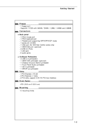
... and 2.88MB Connectors Back panel - 1 PS/2 mouse port - 1 PS/2 keyboard port - 1 Parallel port supporting SPP/EPP/ECP mode - 1 serial port (COM1) - 1 VGA port (for G33 Neo Combo series only) - 1 IEEE1394 port (optional) - 4 USB 2.0 Ports - 1 LAN jack - 6 audio jacks On-Board Pinheaders - 4 USB 2.0 pinheaders - 1 IEEE1394 pinheader (optional) - 1 Chassis Intrusion Switch pinheader -... - 1 PCI Express x 16 slot - 3 PCI Express x 1 slots - 2 PCI slots, support 3.3V/ 5V PCI bus Interface Form Factor - Getting Started Floppy - 1 floppy port - ATX (30.5 cm X 22.5 cm) Mounting - 6 mounting holes 1-3
... and 2.88MB Connectors Back panel - 1 PS/2 mouse port - 1 PS/2 keyboard port - 1 Parallel port supporting SPP/EPP/ECP mode - 1 serial port (COM1) - 1 VGA port (for G33 Neo Combo series only) - 1 IEEE1394 port (optional) - 4 USB 2.0 Ports - 1 LAN jack - 6 audio jacks On-Board Pinheaders - 4 USB 2.0 pinheaders - 1 IEEE1394 pinheader (optional) - 1 Chassis Intrusion Switch pinheader -... - 1 PCI Express x 16 slot - 3 PCI Express x 1 slots - 2 PCI slots, support 3.3V/ 5V PCI bus Interface Form Factor - Getting Started Floppy - 1 floppy port - ATX (30.5 cm X 22.5 cm) Mounting - 6 mounting holes 1-3
User Guide
Page 14
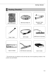
Packing Checklist Getting Started MSI motherboard MSI Driver/Utility CD Standard Cable (Optional) Power Cable SATA Cable USB Bracket (Optional) Back IO Shield 1394 Bracket (Optional) User's Guide * The pictures are for reference only and may vary from the packing contents of the product you purchased. 1-5
Packing Checklist Getting Started MSI motherboard MSI Driver/Utility CD Standard Cable (Optional) Power Cable SATA Cable USB Bracket (Optional) Back IO Shield 1394 Bracket (Optional) User's Guide * The pictures are for reference only and may vary from the packing contents of the product you purchased. 1-5

User Guide
Page 15
Hardware Setup Chapter 2 Hardware Setup This chapter provides you install in holding the components and follow the installation procedures. Static electricity may damage the components. 2-1 For some components, if you with the information about hardware setup procedures. While doing the installation, be careful in the wrong orientation, the components will not work properly. Use a grounded wrist strap before handling computer components.
Hardware Setup Chapter 2 Hardware Setup This chapter provides you install in holding the components and follow the installation procedures. Static electricity may damage the components. 2-1 For some components, if you with the information about hardware setup procedures. While doing the installation, be careful in the wrong orientation, the components will not work properly. Use a grounded wrist strap before handling computer components.
User Guide
Page 17
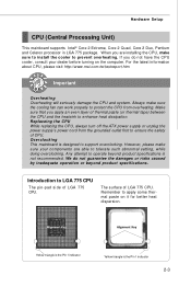
... triangle is the Pin 1 indicator Yellow triangle is designed to support overclocking. For the latest information about CPU, please visit http://www.msi.com.tw/testreport.htm Important Overheating Overheating will seriously damage the CPU and system. However, please make sure to install the cooler to ...risks caused by inadequate operation or beyond product specifications is not recommended. Replaceing the CPU While replacing the CPU, always turn off the ATX power supply or unplug the power supply's power cord from overheating. We do not have the CPU cooler, consult your components are ...
... triangle is the Pin 1 indicator Yellow triangle is designed to support overclocking. For the latest information about CPU, please visit http://www.msi.com.tw/testreport.htm Important Overheating Overheating will seriously damage the CPU and system. However, please make sure to install the cooler to ...risks caused by inadequate operation or beyond product specifications is not recommended. Replaceing the CPU While replacing the CPU, always turn off the ATX power supply or unplug the power supply's power cord from overheating. We do not have the CPU cooler, consult your components are ...
User Guide
Page 18
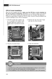
Meanwhile, do not forget to install the CPU & cooler correctly. Do not touch the CPU socket pins to protect the socket pin. 2. W rong installation will cause the damage of your system. 2. Before you are installing the CPU, make sure the CPU has a cooler attached on the top to protect the contact from lever hinge side (as the arrow shows). 3. Remove the cap from damage. The pins of the CPU land side cover depends on your CPU & mainboard. 1. Open the load lever. MS-7365 Mainboard CPU & Cooler Installation W hen you install the CPU, always cover it to prevent ...
Meanwhile, do not forget to install the CPU & cooler correctly. Do not touch the CPU socket pins to protect the socket pin. 2. W rong installation will cause the damage of your system. 2. Before you are installing the CPU, make sure the CPU has a cooler attached on the top to protect the contact from lever hinge side (as the arrow shows). 3. Remove the cap from damage. The pins of the CPU land side cover depends on your CPU & mainboard. 1. Open the load lever. MS-7365 Mainboard CPU & Cooler Installation W hen you install the CPU, always cover it to prevent ...

User Guide
Page 19
alignment key 7. Cover the load plate onto the p ac k age. 2-5 After confirming the CPU direction for correct mating, put down the CPU in the socket housing frame. Note that the alignment keys are matched. Hardware Setup 6. Visually inspect if the CPU is seated well into the socket. If not, take out the CPU with pure vertical motion and reinstall. 8. Be sure to grasp on the edge of the CPU base. 5. Lift the load lever up and open the load plate.
alignment key 7. Cover the load plate onto the p ac k age. 2-5 After confirming the CPU direction for correct mating, put down the CPU in the socket housing frame. Note that the alignment keys are matched. Hardware Setup 6. Visually inspect if the CPU is seated well into the socket. If not, take out the CPU with pure vertical motion and reinstall. 8. Be sure to grasp on the edge of the CPU base. 5. Lift the load lever up and open the load plate.
User Guide
Page 20
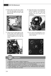
locking switch Important 1. Mainboard photos shown in this section are correctly inserted. Press down the cooler until its four clips get wedged into the holes of the mainboard. 11. The appearance of the CPU/ cooler installation only. Turn over the mainboard to fasten the cooler. Push down the load lever lightly onto the load plate, and then secure the lever with the hook under retention tab. 10. Press the four hooks down to confirm that the clip-ends are for demonstration of your CPU socket pin with the heatsink. Whenever CPU is not installed, always protect ...
locking switch Important 1. Mainboard photos shown in this section are correctly inserted. Press down the cooler until its four clips get wedged into the holes of the mainboard. 11. The appearance of the CPU/ cooler installation only. Turn over the mainboard to fasten the cooler. Push down the load lever lightly onto the load plate, and then secure the lever with the hook under retention tab. 10. Press the four hooks down to confirm that the clip-ends are for demonstration of your CPU socket pin with the heatsink. Whenever CPU is not installed, always protect ...

User Guide
Page 21
... standard is not backward compatible, you are not interchangeable with two data bus lines simultaneously. For more information on compatible components, please visit http://www.msi.com.
... standard is not backward compatible, you are not interchangeable with two data bus lines simultaneously. For more information on compatible components, please visit http://www.msi.com.
User Guide
Page 22
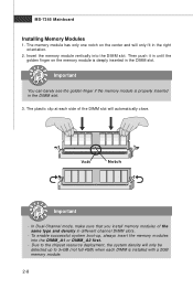
Insert the memory module vertically into the DIMM _A1 or DIMM _A2 first. - Volt Notch Important - To enable successful system boot-up to the chipset resource deployment, the system density will only be detected up , always insert the memory modules into the DIMM slot. MS-7365 Mainboard Installing Memory Modules 1. The memory module has only one notch on the memory module is deeply inserted in the right orientation. 2. Important You can barely see the golden finger if the memory module is installed with a 2GB memory module. 2-8 Due to 3+GB (not full 4GB) when each side ...
Insert the memory module vertically into the DIMM _A1 or DIMM _A2 first. - Volt Notch Important - To enable successful system boot-up to the chipset resource deployment, the system density will only be detected up , always insert the memory modules into the DIMM slot. MS-7365 Mainboard Installing Memory Modules 1. The memory module has only one notch on the memory module is deeply inserted in the right orientation. 2. Important You can barely see the golden finger if the memory module is installed with a 2GB memory module. 2-8 Due to 3+GB (not full 4GB) when each side ...
User Guide
Page 23
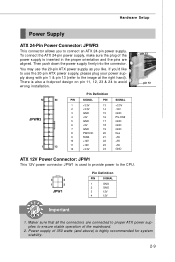
... 19 GND 8 PW R OK 20 Res 9 5VSB 21 +5V 10 +12V 22 +5V 11 +12V 23 +5V 12 +3.3V 24 GND pin 13 pin 12 ATX 12V Power Connector: JPW1 This 12V power connector JPW 1 is highly recommended for system stability. 2-9 You may use the 20-pin...-pin power supply, make sure the plug of the power supply is inserted in the proper orientation and the pins are connected to proper ATX power supplies to ensure stable operation of 350 watts (and above) is used to provide power to the CPU. 3 4 1 2 JPW1 Pin Definition PIN SIGNAL 1 GND 2 ...
... 19 GND 8 PW R OK 20 Res 9 5VSB 21 +5V 10 +12V 22 +5V 11 +12V 23 +5V 12 +3.3V 24 GND pin 13 pin 12 ATX 12V Power Connector: JPW1 This 12V power connector JPW 1 is highly recommended for system stability. 2-9 You may use the 20-pin...-pin power supply, make sure the plug of the power supply is inserted in the proper orientation and the pins are connected to proper ATX power supplies to ensure stable operation of 350 watts (and above) is used to provide power to the CPU. 3 4 1 2 JPW1 Pin Definition PIN SIGNAL 1 GND 2 ...
User Guide
Page 24
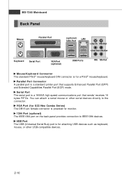
... monitor. 1394 Port (optional) The IEEE1394 port on the back panel provides connection to the connector. Serial Port The serial port is provided for G33 Neo Combo Series) The DB15-pin female connector is a 16550A high speed communications port that supports Enhanced Parallel Port (EPP) and Extended Capabilities Parallel Port (ECP) mode...
... monitor. 1394 Port (optional) The IEEE1394 port on the back panel provides connection to the connector. Serial Port The serial port is provided for G33 Neo Combo Series) The DB15-pin female connector is a 16550A high speed communications port that supports Enhanced Parallel Port (EPP) and Extended Capabilities Parallel Port (ECP) mode...

User Guide
Page 25
Hardware Setup LAN (RJ-45) Jack The standard RJ-45 jack is for audio devices. Activity Indicator Link Indicator LED Color Left Orange Green Right Orange LED State condition Off LAN link is communicating with another computer on the LAN. Audio Ports These audio connectors are used for microphones. CS-Out (Orange) - Line-In (Blue) - Side-Surround Out 7.1 channel mode. 2-11 You can differentiate the color of the audio jacks for speakers or headphones. You can connect a network cable to single Local Area Network (LAN). Line-Out (Green) - SS-Out (Gray) - On (...
Hardware Setup LAN (RJ-45) Jack The standard RJ-45 jack is for audio devices. Activity Indicator Link Indicator LED Color Left Orange Green Right Orange LED State condition Off LAN link is communicating with another computer on the LAN. Audio Ports These audio connectors are used for microphones. CS-Out (Orange) - Line-In (Blue) - Side-Surround Out 7.1 channel mode. 2-11 You can differentiate the color of the audio jacks for speakers or headphones. You can connect a network cable to single Local Area Network (LAN). Line-Out (Green) - SS-Out (Gray) - On (...
