User Guide
Page 4
... the separation between the equipment and receiver. † Connect the equipment into an outlet on a circuit different from that to radio communications. Micro-Star International MS-7365 This device complies with Part 15 of the FCC Rules. iv power cord, if any interference received, including interference that interference will not occur in...
... the separation between the equipment and receiver. † Connect the equipment into an outlet on a circuit different from that to radio communications. Micro-Star International MS-7365 This device complies with Part 15 of the FCC Rules. iv power cord, if any interference received, including interference that interference will not occur in...
User Guide
Page 10
Designed to fit the advanced Intel® Core 2 Extreme, Core 2 Quad, Core 2 Duo, Pentium and Celeron processor, the P35 Neo Combo/ G33 Neo Combo Series deliver a high performance and professional desktop platform solution. 1-1 The P35 Neo Combo/ G33 Neo Combo Series mainboards are based on Intel® P35/G33 & ICH9/ICH9R chipsets for choosing the P35 Neo Combo/ G33 Neo Combo Series (MS-7365 v1.X) ATX mainboard. Getting Started Chapter 1 Getting Started Thank you for optimal system efficiency.
Designed to fit the advanced Intel® Core 2 Extreme, Core 2 Quad, Core 2 Duo, Pentium and Celeron processor, the P35 Neo Combo/ G33 Neo Combo Series deliver a high performance and professional desktop platform solution. 1-1 The P35 Neo Combo/ G33 Neo Combo Series mainboards are based on Intel® P35/G33 & ICH9/ICH9R chipsets for choosing the P35 Neo Combo/ G33 Neo Combo Series (MS-7365 v1.X) ATX mainboard. Getting Started Chapter 1 Getting Started Thank you for optimal system efficiency.
User Guide
Page 11
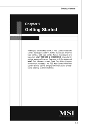
North Bridge: Intel® P35/ G33 (optional) - South Bridge: Intel® ICH9/ ICH9R (optional) Memory Support - 2 DDR2 DIMMs support DDR2 800/ 667 SDRAM (240pin/ non- Supports 7.1 channels audio out - MS-7365 Mainboard Mainboard Specifications Processor Support - ECC/ 4GB Max) - 2 DDR3 DIMMs support DDR3 ...2 Extreme, Core 2 Quad, Core 2 Duo, Pentium and Celeron in the LGA775 package (For the latest information about CPU, please visit http://www.msi. Transfer rate is controlled by Marvell 88SE6111 - SATA1~6 support RAID 0/ 1/ 0+1/ 5 or JBOD mode (for ICH9R only, optional) 1-2 com.tw...
North Bridge: Intel® P35/ G33 (optional) - South Bridge: Intel® ICH9/ ICH9R (optional) Memory Support - 2 DDR2 DIMMs support DDR2 800/ 667 SDRAM (240pin/ non- Supports 7.1 channels audio out - MS-7365 Mainboard Mainboard Specifications Processor Support - ECC/ 4GB Max) - 2 DDR3 DIMMs support DDR3 ...2 Extreme, Core 2 Quad, Core 2 Duo, Pentium and Celeron in the LGA775 package (For the latest information about CPU, please visit http://www.msi. Transfer rate is controlled by Marvell 88SE6111 - SATA1~6 support RAID 0/ 1/ 0+1/ 5 or JBOD mode (for ICH9R only, optional) 1-2 com.tw...
User Guide
Page 18
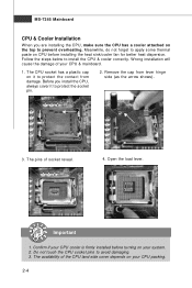
... CPU socket has a plastic cap on it to protect the socket pin. 2. The pins of your CPU & mainboard. 1. Follow the steps below to avoid damaging. 3. MS-7365 Mainboard CPU & Cooler Installation W hen you install the CPU, always cover it to protect the contact from lever hinge side (as the arrow shows). 3. Important 1.
... CPU socket has a plastic cap on it to protect the socket pin. 2. The pins of your CPU & mainboard. 1. Follow the steps below to avoid damaging. 3. MS-7365 Mainboard CPU & Cooler Installation W hen you install the CPU, always cover it to protect the contact from lever hinge side (as the arrow shows). 3. Important 1.
User Guide
Page 20
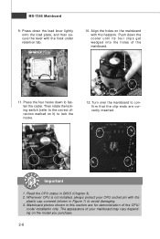
... Figure 1) to confirm that the clip-ends are for demonstration of your CPU socket pin with the heatsink. Turn over the mainboard to avoid damaging. 3. MS-7365 Mainboard 9. Whenever CPU is not installed, always protect your mainboard may vary depending on the mainboard with the plastic cap covered (shown in BIOS (Chapter...
... Figure 1) to confirm that the clip-ends are for demonstration of your CPU socket pin with the heatsink. Turn over the mainboard to avoid damaging. 3. MS-7365 Mainboard 9. Whenever CPU is not installed, always protect your mainboard may vary depending on the mainboard with the plastic cap covered (shown in BIOS (Chapter...
User Guide
Page 22
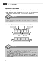
... will automatically close. Volt Notch Important - Due to 3+GB (not full 4GB) when each side of the same type and density in the DIMM slot. 3. MS-7365 Mainboard Installing Memory Modules 1.
... will automatically close. Volt Notch Important - Due to 3+GB (not full 4GB) when each side of the same type and density in the DIMM slot. 3. MS-7365 Mainboard Installing Memory Modules 1.
User Guide
Page 24
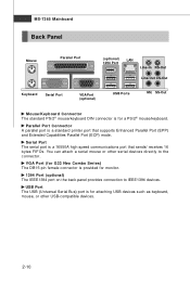
MS-7365 Mainboard Back Panel Mouse Parallel Port (optional) LAN 1394 Port Line-In RS-Out Line-Out CS-Out Keyboard Serial Port VGA Port (optional) USB ... USB devices such as keyboard, mouse, or other serial devices directly to IEEE1394 devices. USB Port The USB (Universal Serial Bus) port is for G33 Neo Combo Series) The DB15-pin female connector is a 16550A high speed communications port that supports Enhanced Parallel Port (EPP) and Extended Capabilities Parallel Port (ECP) mode...
MS-7365 Mainboard Back Panel Mouse Parallel Port (optional) LAN 1394 Port Line-In RS-Out Line-Out CS-Out Keyboard Serial Port VGA Port (optional) USB ... USB devices such as keyboard, mouse, or other serial devices directly to IEEE1394 devices. USB Port The USB (Universal Serial Bus) port is for G33 Neo Combo Series) The DB15-pin female connector is a 16550A high speed communications port that supports Enhanced Parallel Port (EPP) and Extended Capabilities Parallel Port (ECP) mode...
User Guide
Page 26
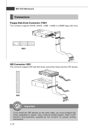
MS-7365 Mainboard Connectors Floppy Disk Drive Connector: FDD1 This connector supports 360KB, 720KB, 1.2MB, 1.44MB or 2.88MB floppy disk drive. IDE1 Important If you install two IDE devices on the same cable, you must configure the drives separately to IDE device's documentation supplied by setting jumpers. Refer to master / slave mode by the vendors for jumper setting instructions. 2-12 FDD1 IDE Connector: IDE1 This connector supports IDE hard disk drives, optical disk drives and other IDE devices.
MS-7365 Mainboard Connectors Floppy Disk Drive Connector: FDD1 This connector supports 360KB, 720KB, 1.2MB, 1.44MB or 2.88MB floppy disk drive. IDE1 Important If you install two IDE devices on the same cable, you must configure the drives separately to IDE device's documentation supplied by setting jumpers. Refer to master / slave mode by the vendors for jumper setting instructions. 2-12 FDD1 IDE Connector: IDE1 This connector supports IDE hard disk drives, optical disk drives and other IDE devices.
User Guide
Page 28
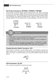
..., the switch will be connected to the actual CPU temperature. GND 2 CINTRU 1 JCI1 CD-In Connector: CD_IN1 This connector is Ground and should be short. MS-7365 Mainboard Fan Power Connectors: CPUFAN1, SYSFAN1, SYSFAN2 The fan power connectors support system cooling fan with 3 or 4 pins power connector are both available for CPUFAN1...
..., the switch will be connected to the actual CPU temperature. GND 2 CINTRU 1 JCI1 CD-In Connector: CD_IN1 This connector is Ground and should be short. MS-7365 Mainboard Fan Power Connectors: CPUFAN1, SYSFAN1, SYSFAN2 The fan power connectors support system cooling fan with 3 or 4 pins power connector are both available for CPUFAN1...
User Guide
Page 30
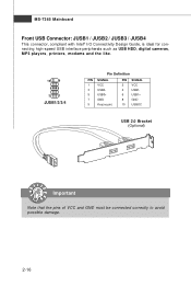
MS-7365 Mainboard Front USB Connector: JUSB1 / JUSB2 / JUSB3 / JUSB4 This connector, compliant with Intel® I/O Connectivity Design Guide, is ideal for connecting high-speed USB interface peripherals such as USB HDD, digital cameras, MP3 players, printers, modems and the like. 10 9 2 1 JUSB1/2/3/4 Pin Definition PIN SIGNAL 1 VCC 3 USB0- 5 USB0+ 7 GND 9 Key (no pin) PIN SIGNAL 2 VCC 4 USB1- 6 USB1+ 8 GND 10 USBOC USB 2.0 Bracket (Optional) Important Note that the pins of VCC and GND must be connected correctly to avoid possible damage. 2-16
MS-7365 Mainboard Front USB Connector: JUSB1 / JUSB2 / JUSB3 / JUSB4 This connector, compliant with Intel® I/O Connectivity Design Guide, is ideal for connecting high-speed USB interface peripherals such as USB HDD, digital cameras, MP3 players, printers, modems and the like. 10 9 2 1 JUSB1/2/3/4 Pin Definition PIN SIGNAL 1 VCC 3 USB0- 5 USB0+ 7 GND 9 Key (no pin) PIN SIGNAL 2 VCC 4 USB1- 6 USB1+ 8 GND 10 USBOC USB 2.0 Bracket (Optional) Important Note that the pins of VCC and GND must be connected correctly to avoid possible damage. 2-16
User Guide
Page 32
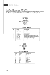
... LED JFP2 Pin Definition PIN SIGNAL 1 GND 2 SPK- 3 SLED 4 BUZ+ 5 PLED 6 BUZ- 7 NC 8 SPK+ DESCRIPTION Ground SpeakerSuspend LED Buzzer+ Power LED BuzzerNo connection Speaker+ 2-18 MS-7365 Mainboard Front Panel Connectors: JFP1, JFP2 These connectors are for electrical connection to GND Reset Switch high reference pull-up Power Switch low reference pull...
... LED JFP2 Pin Definition PIN SIGNAL 1 GND 2 SPK- 3 SLED 4 BUZ+ 5 PLED 6 BUZ- 7 NC 8 SPK+ DESCRIPTION Ground SpeakerSuspend LED Buzzer+ Power LED BuzzerNo connection Speaker+ 2-18 MS-7365 Mainboard Front Panel Connectors: JFP1, JFP2 These connectors are for electrical connection to GND Reset Switch high reference pull-up Power Switch low reference pull...
User Guide
Page 34
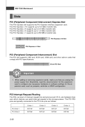
... for the ex pansion card, such as follows: PCI Slot 1 PCI Slot 2 Order 1 INT A# INT B# Order 2 INT B# INT C# Order 3 INT C# INT D# Order 4 INT D# INT A# 2-20 MS-7365 Mainboard Slots PCI (Peripheral Component Interconnect) Express Slot The PCI Express slot supports the PCI Express interface expansion card. The PCI Express x 16 supports up...
... for the ex pansion card, such as follows: PCI Slot 1 PCI Slot 2 Order 1 INT A# INT B# Order 2 INT B# INT C# Order 3 INT C# INT D# Order 4 INT D# INT A# 2-20 MS-7365 Mainboard Slots PCI (Peripheral Component Interconnect) Express Slot The PCI Express slot supports the PCI Express interface expansion card. The PCI Express x 16 supports up...
User Guide
Page 36
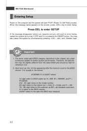
... below appears on the computer and the system will start POST (Power On Self Test) process. Important 1. The items under continuous update for reference only. 2. MS-7365 Mainboard Entering Setup Power on the screen, press key to enter Setup. Upon boot-up, the 1st line appearing after the memory count is usually... digit refers to the model number. 6th digit refers to the chipset as I = Intel, N = nVidia, and V = VIA. 7th - 8th digit refers to the customer as MS = all standard customers.
... below appears on the computer and the system will start POST (Power On Self Test) process. Important 1. The items under continuous update for reference only. 2. MS-7365 Mainboard Entering Setup Power on the screen, press key to enter Setup. Upon boot-up, the 1st line appearing after the memory count is usually... digit refers to the model number. 6th digit refers to the chipset as I = Intel, N = nVidia, and V = VIA. 7th - 8th digit refers to the customer as MS = all standard customers.
User Guide
Page 38
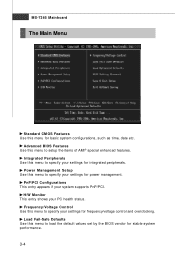
... this menu to specify your settings for power management. Load Fail-Safe Defaults Use this menu for basic system configurations, such as time, date etc. MS-7365 Mainboard The Main Menu Standard CMOS Features Use this menu to load the default values set by the BIOS vendor for stable system performance. 3-4 H/W Monitor...
... this menu to specify your settings for power management. Load Fail-Safe Defaults Use this menu for basic system configurations, such as time, date etc. MS-7365 Mainboard The Main Menu Standard CMOS Features Use this menu to load the default values set by the BIOS vendor for stable system performance. 3-4 H/W Monitor...
User Guide
Page 40
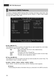
.... The time format is . SATA1 / SATA2 / SATA3 / SATA4 / SATA5 / SATA6 Press to the SATA connector. 3-6 date The date from Sun to Sat, determined by users. MS-7365 Mainboard Standard CMOS Features The items in Standard CMOS Features Menu includes some basic setup items. Use the arrow keys to highlight the item and...
.... The time format is . SATA1 / SATA2 / SATA3 / SATA4 / SATA5 / SATA6 Press to the SATA connector. 3-6 date The date from Sun to Sat, determined by users. MS-7365 Mainboard Standard CMOS Features The items in Standard CMOS Features Menu includes some basic setup items. Use the arrow keys to highlight the item and...
User Guide
Page 42
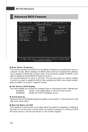
... Num-Lock LED This setting is to [On] will allow users to show the company logo on . Settings are: [Enabled] Shows a still image (logo) on . MS-7365 Mainboard Advanced BIOS Features Boot Sector Protection This function protects the BIOS from accidental corruption by unauthorized users or computer viruses. The only time when...
... Num-Lock LED This setting is to [On] will allow users to show the company logo on . Settings are: [Enabled] Shows a still image (logo) on . MS-7365 Mainboard Advanced BIOS Features Boot Sector Protection This function protects the BIOS from accidental corruption by unauthorized users or computer viruses. The only time when...
User Guide
Page 44
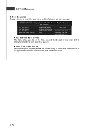
MS-7365 Mainboard Boot Sequence Press to enter the sub-menu and the following screen appears: 1st/ 2nd/ 3rd Boot Device The items allow you to set the first/ second/ third boot device where BIOS attempts to boot from other device. Boot From Other Device Setting the option to [Yes] allows the system to try to boot from the 1st/ 2nd/ 3rd boot device. 3-10 if the system fails to load the disk operating system.
MS-7365 Mainboard Boot Sequence Press to enter the sub-menu and the following screen appears: 1st/ 2nd/ 3rd Boot Device The items allow you to set the first/ second/ third boot device where BIOS attempts to boot from other device. Boot From Other Device Setting the option to [Yes] allows the system to try to boot from the 1st/ 2nd/ 3rd boot device. 3-10 if the system fails to load the disk operating system.
User Guide
Page 46
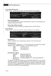
.... Parallel Port There is used PCI busmastering for reading/ writing to IDE drives. Choosing [ECP & EPP] will operate in the EPP mode simultaneously, choose [EPP]. MS-7365 Mainboard On-Chip ATA Devices Press to enter the sub-menu and the following screen appears: COM Port 1 Select an address and corresponding interrupt for...
.... Parallel Port There is used PCI busmastering for reading/ writing to IDE drives. Choosing [ECP & EPP] will operate in the EPP mode simultaneously, choose [EPP]. MS-7365 Mainboard On-Chip ATA Devices Press to enter the sub-menu and the following screen appears: COM Port 1 Select an address and corresponding interrupt for...
User Guide
Page 48
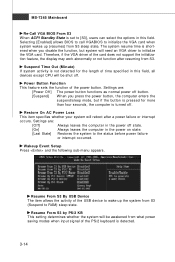
... the system from what power saving modes when input signal of time specified in this field. Therefore, if the VGA driver of the power button. MS-7365 Mainboard Re-Call VGA BIOS From S3 W hen ACPI Standby State is set to [S3], users can select the options in the power on state...
... the system from what power saving modes when input signal of time specified in this field. Therefore, if the VGA driver of the power button. MS-7365 Mainboard Re-Call VGA BIOS From S3 W hen ACPI Standby State is set to [S3], users can select the options in the power on state...
User Guide
Page 50
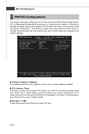
... how long each PCI slot. 3-16 PCI Slot 1/ 2 IRQ These items specify the IRQ line for a longer time and thus improve the effective PCI bandwidth. MS-7365 Mainboard PNP/PCI Configurations This section describes configuring the PCI bus system and PnP (Plug & Play) feature. PCI, or Peripheral Component Interconnect, is a system which...
... how long each PCI slot. 3-16 PCI Slot 1/ 2 IRQ These items specify the IRQ line for a longer time and thus improve the effective PCI bandwidth. MS-7365 Mainboard PNP/PCI Configurations This section describes configuring the PCI bus system and PnP (Plug & Play) feature. PCI, or Peripheral Component Interconnect, is a system which...


