
User Guide
Page 2
... of M ICRO-STAR INTERNATIONAL. Revision History Revision V1.0 Revision History First release for P31 Neo Series Date July 2007 Technical Support If a problem arises with your place of purchase or local distributor. Visit the MSI website for further guidance. Copyright Notice The material in this document, but no solution can be obtained from the user's manual, please contact your...
... of M ICRO-STAR INTERNATIONAL. Revision History Revision V1.0 Revision History First release for P31 Neo Series Date July 2007 Technical Support If a problem arises with your place of purchase or local distributor. Visit the MSI website for further guidance. Copyright Notice The material in this document, but no solution can be obtained from the user's manual, please contact your...

User Guide
Page 8
... 1-2 Mainboard Layout 1-4 Packing Checklist 1-5 Chapter 2 Hardware Setup 2-1 Quick Components Guide 2-2 CPU (Central Processing Unit 2-3 Memory ...2-7 Power Supply ...2-9 Back Panel ...2-10 Connectors ...2-11 Jumper ...2-18 Slots ...2-19 Chapter 3 BIOS Setup 3-1 Entering Setup ...3-2 The Main Menu ...3-4 Standard CMOS Features 3-6 Advanced BIOS Features 3-9 Integrated Peripherals 3-12 Power Management Setup 3-14 PNP/PCI Configurations 3-16 H/W Monitor ...3-18 Frequency/Voltage Control 3-19 Load Fail-Safe/ Optimized Defaults 3-23 BIOS Setting Password 3-24 Appendix A Dual Core...
... 1-2 Mainboard Layout 1-4 Packing Checklist 1-5 Chapter 2 Hardware Setup 2-1 Quick Components Guide 2-2 CPU (Central Processing Unit 2-3 Memory ...2-7 Power Supply ...2-9 Back Panel ...2-10 Connectors ...2-11 Jumper ...2-18 Slots ...2-19 Chapter 3 BIOS Setup 3-1 Entering Setup ...3-2 The Main Menu ...3-4 Standard CMOS Features 3-6 Advanced BIOS Features 3-9 Integrated Peripherals 3-12 Power Management Setup 3-14 PNP/PCI Configurations 3-16 H/W Monitor ...3-18 Frequency/Voltage Control 3-19 Load Fail-Safe/ Optimized Defaults 3-23 BIOS Setting Password 3-24 Appendix A Dual Core...

User Guide
Page 9
Clock ...A-6 Voltage ...A-7 FAN Speed ...A-8 Temperature ...A-9 User Profile ...A-10 Appendix B Realtek ALC888 Audio B-1 Installing the Realtek Audio Driver B-2 Software Configuration B-4 Hardware Setup B-19 ix
Clock ...A-6 Voltage ...A-7 FAN Speed ...A-8 Temperature ...A-9 User Profile ...A-10 Appendix B Realtek ALC888 Audio B-1 Installing the Realtek Audio Driver B-2 Software Configuration B-4 Hardware Setup B-19 ix
User Guide
Page 12
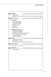
Getting Started Floppy - 1 floppy port - Supports 1 FDD with 360KB, 720KB, 1.2MB, 1.44MB and 2.88MB Connectors Back panel - 1 PS/2 mouse port - 1 PS/2 keyboard port - 1 serial port (COM1) - 4 USB 2.0 Ports - 1 LAN jack - 6 audio jacks On-Board Pinheaders - 1 Parallel port pinheader - 2 USB 2.0 pinheaders - 1 Chassis Intrusion Switch pinheader - 1 Front Panel Audio pinheader - 1 CD-In pinheader - 1 SPDIF-out pinheader Slots - 1 PCI Express x 16 slot - 1 PCI Express x 1 slots - 3 PCI slots, support 3.3V/ 5V PCI bus Interface Form Factor - ATX (30.5 cm X 21.5 cm) Mounting - 6 mounting holes 1-3...
Getting Started Floppy - 1 floppy port - Supports 1 FDD with 360KB, 720KB, 1.2MB, 1.44MB and 2.88MB Connectors Back panel - 1 PS/2 mouse port - 1 PS/2 keyboard port - 1 serial port (COM1) - 4 USB 2.0 Ports - 1 LAN jack - 6 audio jacks On-Board Pinheaders - 1 Parallel port pinheader - 2 USB 2.0 pinheaders - 1 Chassis Intrusion Switch pinheader - 1 Front Panel Audio pinheader - 1 CD-In pinheader - 1 SPDIF-out pinheader Slots - 1 PCI Express x 16 slot - 1 PCI Express x 1 slots - 3 PCI slots, support 3.3V/ 5V PCI bus Interface Form Factor - ATX (30.5 cm X 21.5 cm) Mounting - 6 mounting holes 1-3...
User Guide
Page 21
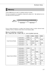
... SS DS/SS SS X X SS DS/SS SS X X X DS/SS X SS X DS/SS SS SS 2-7 tw/index.php?func=testreport DDR2 240-pin, 1.8V 64x2=128 pin 56x2=112 pin Due to chipset limitations, to enable dual channel mode or single channel mode, installing memory modules should refer to the following table. For more information on compatible components, please visit http://global.msi.com.
... SS DS/SS SS X X SS DS/SS SS X X X DS/SS X SS X DS/SS SS SS 2-7 tw/index.php?func=testreport DDR2 240-pin, 1.8V 64x2=128 pin 56x2=112 pin Due to chipset limitations, to enable dual channel mode or single channel mode, installing memory modules should refer to the following table. For more information on compatible components, please visit http://global.msi.com.

User Guide
Page 23
...). Hardware Setup Power Supply ATX 24-Pin Power Connector: ATX1 This connector allows you like. Power supply of the power supply is inserted in the proper orientation and the pins are connected to proper ATX power supplies to the CPU. 4 2 3 1 JPW1 Pin Definition PIN SIGNAL 1 GND 2 GND 3 12V 4 12V Important 1. To connect the ATX 24-pin power supply, make sure the plug of 350 watts (and above) is used to provide power to ensure stable operation of the mainboard...
...). Hardware Setup Power Supply ATX 24-Pin Power Connector: ATX1 This connector allows you like. Power supply of the power supply is inserted in the proper orientation and the pins are connected to proper ATX power supplies to the CPU. 4 2 3 1 JPW1 Pin Definition PIN SIGNAL 1 GND 2 GND 3 12V 4 12V Important 1. To connect the ATX 24-pin power supply, make sure the plug of 350 watts (and above) is used to provide power to ensure stable operation of the mainboard...
User Guide
Page 25
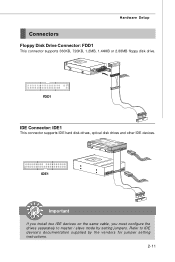
Hardware Setup Connectors Floppy Disk Drive Connector: FDD1 This connector supports 360KB, 720KB, 1.2MB, 1.44MB or 2.88MB floppy disk drive. FDD1 IDE Connector: IDE1 This connector supports IDE hard disk drives, optical disk drives and other IDE devices. IDE1 Important If you install two IDE devices on the same cable, you must configure the drives separately to IDE device's documentation supplied by setting jumpers. Refer to master / slave mode by the vendors for jumper setting instructions. 2-11
Hardware Setup Connectors Floppy Disk Drive Connector: FDD1 This connector supports 360KB, 720KB, 1.2MB, 1.44MB or 2.88MB floppy disk drive. FDD1 IDE Connector: IDE1 This connector supports IDE hard disk drives, optical disk drives and other IDE devices. IDE1 Important If you install two IDE devices on the same cable, you must configure the drives separately to IDE device's documentation supplied by setting jumpers. Refer to master / slave mode by the vendors for jumper setting instructions. 2-11

User Guide
Page 27
... of BIOS Setup. Fan cooler set with speed sensor to the recommended CPU fans at processor's official website or consult the vendors for external audio input. You can install Dual Core Center utility that the red wire is Ground and should be connected to the +12V; You can setup it in H/W Monitor of the CPU fan control. If the mainboard has a System Hardware Monitor chipset on-board, you must use a specially designed fan with 3 or 4 pins power connector are...
... of BIOS Setup. Fan cooler set with speed sensor to the recommended CPU fans at processor's official website or consult the vendors for external audio input. You can install Dual Core Center utility that the red wire is Ground and should be connected to the +12V; You can setup it in H/W Monitor of the CPU fan control. If the mainboard has a System Hardware Monitor chipset on-board, you must use a specially designed fan with 3 or 4 pins power connector are...
User Guide
Page 32
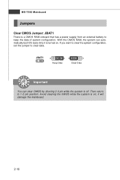
W ith the CMOS RAM, the system can clear CMOS by shorting 2-3 pin while the system is a CMOS RAM onboard that has a power supply from an external battery to keep the data of system configuration. JBAT1 1 3 1 Keep Data 3 1 Clear Data Important You can automatically boot OS every time it will damage the mainboard. 2-18 Then return to clear data. it is on . MS-7392 Mainboard Jumpers Clear CMOS Jumper: JBAT1 There is off. If you want to clear the system configuration, set the jumper to 1-2 pin position. Avoid clearing the CMOS while the system is turned on ;
W ith the CMOS RAM, the system can clear CMOS by shorting 2-3 pin while the system is a CMOS RAM onboard that has a power supply from an external battery to keep the data of system configuration. JBAT1 1 3 1 Keep Data 3 1 Clear Data Important You can automatically boot OS every time it will damage the mainboard. 2-18 Then return to clear data. it is on . MS-7392 Mainboard Jumpers Clear CMOS Jumper: JBAT1 There is off. If you want to clear the system configuration, set the jumper to 1-2 pin position. Avoid clearing the CMOS while the system is turned on ;

User Guide
Page 33
... Slot PCI Express x1 Slot PCI (Peripheral Component Interconnect) Slot The PCI slot supports LAN card, SCSI card, USB card, and other add-on cards that comply with PCI specifications. 32-bit PCI Slot Important When adding or removing expansion cards, make sure that you unplug the power supply first. Hardware Setup Slots PCI (Peripheral Component Interconnect) Express Slot The PCI Express slot supports the PCI Express interface expansion card. The PCI IRQ pins are hardware lines over which devices can send interrupt signals to configure any necessary hardware or software settings...
... Slot PCI Express x1 Slot PCI (Peripheral Component Interconnect) Slot The PCI slot supports LAN card, SCSI card, USB card, and other add-on cards that comply with PCI specifications. 32-bit PCI Slot Important When adding or removing expansion cards, make sure that you unplug the power supply first. Hardware Setup Slots PCI (Peripheral Component Interconnect) Express Slot The PCI Express slot supports the PCI Express interface expansion card. The PCI IRQ pins are hardware lines over which devices can send interrupt signals to configure any necessary hardware or software settings...
User Guide
Page 40
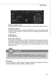
... device information that you to set the type of floppy drives installed. Hard Disk S.M.A.R.T. Floppy A This item allows you connected to a safe place before the hard disk becomes offline. Setting to Auto enables LBA mode if the device supports it and the devices is a utility that is going to fail to the SATA connector. This allows you connect the HD devices to activate the S.M.A.R.T. (Self-Monitoring Analysis & Reporting Technology) capability for the hard disks. Important IDE Primary M aster/Slave and Serial...
... device information that you to set the type of floppy drives installed. Hard Disk S.M.A.R.T. Floppy A This item allows you connected to a safe place before the hard disk becomes offline. Setting to Auto enables LBA mode if the device supports it and the devices is a utility that is going to fail to the SATA connector. This allows you connect the HD devices to activate the S.M.A.R.T. (Self-Monitoring Analysis & Reporting Technology) capability for the hard disks. Important IDE Primary M aster/Slave and Serial...

User Guide
Page 42
... users to use the arrow keys on the full screen at boot. [Disabled] Shows the POST messages at boot. IOAPIC Function This field is powered on the Num Lock key when the system is able to run in APIC mode. Advanced BIOS Features BIOS Setup Full Screen LOGO Display This item enables you to show the company logo on . Enabling APIC mode will turn on . Setting to compliance with PC2001 design guide...
... users to use the arrow keys on the full screen at boot. [Disabled] Shows the POST messages at boot. IOAPIC Function This field is powered on the Num Lock key when the system is able to run in APIC mode. Advanced BIOS Features BIOS Setup Full Screen LOGO Display This item enables you to show the company logo on . Enabling APIC mode will turn on . Setting to compliance with PC2001 design guide...
User Guide
Page 45
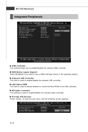
... Controller This setting is used to enable/disable the onboard LAN controller. Onboard LAN Controller This item is used to decide whether to enter the sub-menu and the following screen appears: 3-12 LAN Option ROM This item is used to enable/disable the onboard audio controller. USB Device Legacy Support Select [Enabled] if you to enable/disable the onboard USB controller. MS-7392 Mainboard Integrated Peripherals USB Controller This setting allows you need to use a USB-interfaced device in the operating system. On-Chip ATA Devices Press to invoke the Boot ROM of the LAN controller...
... Controller This setting is used to enable/disable the onboard LAN controller. Onboard LAN Controller This item is used to decide whether to enter the sub-menu and the following screen appears: 3-12 LAN Option ROM This item is used to enable/disable the onboard audio controller. USB Device Legacy Support Select [Enabled] if you to enable/disable the onboard USB controller. MS-7392 Mainboard Integrated Peripherals USB Controller This setting allows you need to use a USB-interfaced device in the operating system. On-Chip ATA Devices Press to invoke the Boot ROM of the LAN controller...

User Guide
Page 46
... allows you to enable/ disable BIOS to used PCI busmastering for the first serial port. On-Chip SATA Controller These items allow users to IDE drives. Parallel Port M ode This item allows you to enter the sub-menu and the following screen appears: COM Port 1 Select an address and corresponding interrupt for reading/ writing to enable or disable the IDE controller. Parallel Port This item allows you to enable or disable the SATA controller. I/O Device Press to set parallel port.
... allows you to enable/ disable BIOS to used PCI busmastering for the first serial port. On-Chip SATA Controller These items allow users to IDE drives. Parallel Port M ode This item allows you to enter the sub-menu and the following screen appears: COM Port 1 Select an address and corresponding interrupt for reading/ writing to enable or disable the IDE controller. Parallel Port This item allows you to enable or disable the SATA controller. I/O Device Press to set parallel port.
User Guide
Page 48
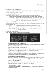
... after a power failure or interrupt occurs. Resume by PCI Device (PME#) W hen set to [Enabled], the feature allows your system to RAM) sleep state. Power Button Function This feature sets the function of the PS/2 keyboard is turned off button. [Suspend] W hen you press the power button, the computer enters the suspend/sleep mode, but if the button is pressed for DOS). Settings are : [PowerOn/Off] The power button functions as normal power off...
... after a power failure or interrupt occurs. Resume by PCI Device (PME#) W hen set to [Enabled], the feature allows your system to RAM) sleep state. Power Button Function This feature sets the function of the PS/2 keyboard is turned off button. [Suspend] W hen you press the power button, the computer enters the suspend/sleep mode, but if the button is pressed for DOS). Settings are : [PowerOn/Off] The power button functions as normal power off...
User Guide
Page 49
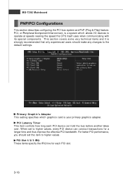
... covers some very technical items and it is your primary graphics adapter. MS-7392 Mainboard PNP/PCI Configurations This section describes configuring the PCI bus system and PnP (Plug & Play) feature. PCI, or Peripheral Component Interconnect, is a system which graphics card is strongly recommended that only experienced users should set to operate at speeds nearing the speed the CPU itself uses when communicating with its special components.
... covers some very technical items and it is your primary graphics adapter. MS-7392 Mainboard PNP/PCI Configurations This section describes configuring the PCI bus system and PnP (Plug & Play) feature. PCI, or Peripheral Component Interconnect, is a system which graphics card is strongly recommended that only experienced users should set to operate at speeds nearing the speed the CPU itself uses when communicating with its special components.
User Guide
Page 51
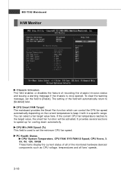
... with in a specific range. CPU Min.FAN Speed (%) This field is once opened. CPU Smart FAN Target The mainboard provides the Smart Fan function which can select a fan target value here. MS-7392 Mainboard H/W Monitor Chassis Intrusion The field enables or disables the feature of recording the chassis intrusion status and issuing a warning message if the chassis is used to set the field to [Reset]. To clear the warning message, set the minimum CPU fan speed.
... with in a specific range. CPU Min.FAN Speed (%) This field is once opened. CPU Smart FAN Target The mainboard provides the Smart Fan function which can select a fan target value here. MS-7392 Mainboard H/W Monitor Chassis Intrusion The field enables or disables the feature of recording the chassis intrusion status and issuing a warning message if the chassis is used to set the field to [Reset]. To clear the warning message, set the minimum CPU fan speed.

User Guide
Page 53
...%. 6th level of overclocking options. DRAM CAS# Latency W hen the Configuration DRAM Timing by SPD sets to select the CPU Front Side Bus clock frequency (in clock cycles) before SDRAM starts a read command after you to enter the sub-menu and the following screen appears. Adjust CPU FSB Frequency This item allows you to [Disabled], the field is adjustable.This controls the CAS latency, which support speedstep technology. Read-only. Adjust...
...%. 6th level of overclocking options. DRAM CAS# Latency W hen the Configuration DRAM Timing by SPD sets to select the CPU Front Side Bus clock frequency (in clock cycles) before SDRAM starts a read command after you to enter the sub-menu and the following screen appears. Adjust CPU FSB Frequency This item allows you to [Disabled], the field is adjustable.This controls the CAS latency, which support speedstep technology. Read-only. Adjust...
User Guide
Page 55
... Spectrum value is, the greater the EMI is reduced, and the system will remove (turn off) clocks from empty DIMM and PCI slots to increase the CPU voltage. M emory Voltage Adjusting the memory voltage can introduce a temporary boost in clock speed which may just cause your overclocked processor to select the PCIE frequency (in clock speed which may just cause your local EMI regulation. 3. The Spread Spectrum function...
... Spectrum value is, the greater the EMI is reduced, and the system will remove (turn off) clocks from empty DIMM and PCI slots to increase the CPU voltage. M emory Voltage Adjusting the memory voltage can introduce a temporary boost in clock speed which may just cause your overclocked processor to select the PCIE frequency (in clock speed which may just cause your local EMI regulation. 3. The Spread Spectrum function...
User Guide
Page 60
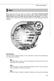
... MB button to enable or disable the Dynamic Overclocking Technology. DOT Click DOT button to read current GPU temperature, GPU clock and memory clock of graphics card will show below . Dual Core Center Main Before using this utility. VGA Click VGA button to install with the version 8.26 or newer driver)/ V046 or V060 graphics card can activate the full function of mainboard will show below . Introduction: Click each button appearing above to enter sub-menu to make further configuration...
... MB button to enable or disable the Dynamic Overclocking Technology. DOT Click DOT button to read current GPU temperature, GPU clock and memory clock of graphics card will show below . Dual Core Center Main Before using this utility. VGA Click VGA button to install with the version 8.26 or newer driver)/ V046 or V060 graphics card can activate the full function of mainboard will show below . Introduction: Click each button appearing above to enter sub-menu to make further configuration...

