User Manual
Page 8
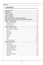
... 1 Getting Started 1-1 Mainboard Specifications 1-2 Mainboard Layout 1-4 Packing Checklist 1-5 Chapter 2 Hardware Setup 2-1 Quick Components Guide 2-2 CPU (Central Processing Unit 2-3 Memory 2-6 Power Supply 2-8 Back Panel 2-9 Connectors 2-11 Jumpers 2-19 Switch 2-20 Slots 2-21 LED Status Indicators 2-25 Chapter 3 BIOS Setup 3-1 Entering Setup 3-2 The Main Menu 3-4 Standard CMOS Features 3-6 Advanced BIOS Features 3-9 Integrated Peripherals...
... 1 Getting Started 1-1 Mainboard Specifications 1-2 Mainboard Layout 1-4 Packing Checklist 1-5 Chapter 2 Hardware Setup 2-1 Quick Components Guide 2-2 CPU (Central Processing Unit 2-3 Memory 2-6 Power Supply 2-8 Back Panel 2-9 Connectors 2-11 Jumpers 2-19 Switch 2-20 Slots 2-21 LED Status Indicators 2-25 Chapter 3 BIOS Setup 3-1 Entering Setup 3-2 The Main Menu 3-4 Standard CMOS Features 3-6 Advanced BIOS Features 3-9 Integrated Peripherals...
User Manual
Page 26
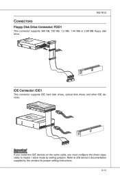
... Connector Important If you install two IDE devices on the same cable, you must configure the drives separately to IDE device's documentation supplied by setting jumpers. MS-7612 Connectors Floppy Disk Drive Connector: FDD1 This connector supports 360 KB, 720 KB, 1.2 MB, 1.44 MB or 2.88 MB floppy disk drive. Fl... Connector: IDE1 This connector supports IDE hard disk drives, optical disk drives and other IDE devices. Refer to master / slave mode by the vendors for jumper setting instructions. 2-11
... Connector Important If you install two IDE devices on the same cable, you must configure the drives separately to IDE device's documentation supplied by setting jumpers. MS-7612 Connectors Floppy Disk Drive Connector: FDD1 This connector supports 360 KB, 720 KB, 1.2 MB, 1.44 MB or 2.88 MB floppy disk drive. Fl... Connector: IDE1 This connector supports IDE hard disk drives, optical disk drives and other IDE devices. Refer to master / slave mode by the vendors for jumper setting instructions. 2-11
User Manual
Page 34
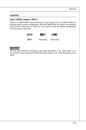
Then return to clear data. 1 JBAT1 1 Keep Data 1 Clear Data Important You can automatically boot OS every time it will damage the mainboard. 2-19 Avoid clearing the CMOS while the system is off. it is a CMOS RAM onboard that has a power supply from an external battery to keep the data of system configuration. With the CMOS RAM, the system can clear CMOS by shorting 2-3 pin while the system is on . If you want to clear the system configuration, set the jumper to 1-2 pin position. MS-7612 Jumpers Clear CMOS Jumper: JBAT1 There is turned on ;
Then return to clear data. 1 JBAT1 1 Keep Data 1 Clear Data Important You can automatically boot OS every time it will damage the mainboard. 2-19 Avoid clearing the CMOS while the system is off. it is a CMOS RAM onboard that has a power supply from an external battery to keep the data of system configuration. With the CMOS RAM, the system can clear CMOS by shorting 2-3 pin while the system is on . If you want to clear the system configuration, set the jumper to 1-2 pin position. MS-7612 Jumpers Clear CMOS Jumper: JBAT1 There is turned on ;
User Manual
Page 36
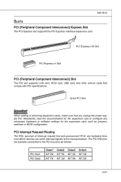
... unplug the power supply first. The PCI IRQ pins are hardware lines over which devices can send interrupt signals to the PCI bus pins as jumpers, switches or BIOS configuration. PCI Interrupt Request Routing The IRQ, acronym of interrupt request line and pronounced I-R-Q, are typically connected to the microprocessor. Meanwhile, read...
... unplug the power supply first. The PCI IRQ pins are hardware lines over which devices can send interrupt signals to the PCI bus pins as jumpers, switches or BIOS configuration. PCI Interrupt Request Routing The IRQ, acronym of interrupt request line and pronounced I-R-Q, are typically connected to the microprocessor. Meanwhile, read...


