User Guide
Page 3
... a registered trademark of American Megatrends Inc. Alternatively, please try the following help resources for FAQ, technical guide, BIOS updates, driver updates, and other information: http://www.msi.com.tw/ Contact our technical staff at: support@msi.com.tw iii Copyright Notice The material in the preparation of this document is a registered trademark of... obtained from the user's manual, please contact your place of AMD Corporation. Trademarks All trademarks are registered trademarks of purchase or local distributor. Visit the MSI website for further guidance.
... a registered trademark of American Megatrends Inc. Alternatively, please try the following help resources for FAQ, technical guide, BIOS updates, driver updates, and other information: http://www.msi.com.tw/ Contact our technical staff at: support@msi.com.tw iii Copyright Notice The material in the preparation of this document is a registered trademark of... obtained from the user's manual, please contact your place of AMD Corporation. Trademarks All trademarks are registered trademarks of purchase or local distributor. Visit the MSI website for further guidance.
User Guide
Page 5
... Connector: JPW1 2-11 Back Panel 2-12 Mouse Connector 2-12 Keyboard Connector 2-12 v Getting Started 1-1 Mainboard Specifications 1-2 Mainboard Layout 1-4 MSI Special Features 1-5 Color Management 1-5 Core Center 1-6 Core Cell™ Chip 1-8 Dynamic Overclocking Technology 1-9 Live BIOS™/Live Driver 1-10 D-Bracket™ 2 (Optional 1-11 Chapter 2. CONTENTS FCC-B Radio Frequency Interference Statement iii Copyright Notice...
... Connector: JPW1 2-11 Back Panel 2-12 Mouse Connector 2-12 Keyboard Connector 2-12 v Getting Started 1-1 Mainboard Specifications 1-2 Mainboard Layout 1-4 MSI Special Features 1-5 Color Management 1-5 Core Center 1-6 Core Cell™ Chip 1-8 Dynamic Overclocking Technology 1-9 Live BIOS™/Live Driver 1-10 D-Bracket™ 2 (Optional 1-11 Chapter 2. CONTENTS FCC-B Radio Frequency Interference Statement iii Copyright Notice...

User Guide
Page 6
BIOS Setup 3-1 Entering Setup 3-2 Selecting the First Boot Device 3-2 vi USB 2.0 Connectors 2-13 IEEE1394 Ports (Optional 2-13 Serial Port Connector: COM A 2-14 RJ-45 LAN Jack (...
BIOS Setup 3-1 Entering Setup 3-2 Selecting the First Boot Device 3-2 vi USB 2.0 Connectors 2-13 IEEE1394 Ports (Optional 2-13 Serial Port Connector: COM A 2-14 RJ-45 LAN Jack (...

User Guide
Page 7
Using 4- or 6-Channel Audio Function A-2 vii Control Keys 3-3 Getting Help 3-3 The Main Menu 3-4 Standard CMOS Features 3-6 Advanced BIOS Features 3-8 Advanced Chipset Features 3-11 Power Management Features 3-14 PNP/PCI Configurations 3-18 Integrated Peripherals 3-20 PC Health Status 3-23 Frequency/Voltage Control 3-24 Set Supervisor/User Password 3-26 Load High Performance/BIOS Setup Defaults 3-27 Appendix. or 6-Channel Audio Function A-1 Using 4-
Using 4- or 6-Channel Audio Function A-2 vii Control Keys 3-3 Getting Help 3-3 The Main Menu 3-4 Standard CMOS Features 3-6 Advanced BIOS Features 3-8 Advanced Chipset Features 3-11 Power Management Features 3-14 PNP/PCI Configurations 3-18 Integrated Peripherals 3-20 PC Health Status 3-23 Frequency/Voltage Control 3-24 Set Supervisor/User Password 3-26 Load High Performance/BIOS Setup Defaults 3-27 Appendix. or 6-Channel Audio Function A-1 Using 4-

User Guide
Page 10
... with 360K, 720K, 1.2M, 1.44M and 2.88Mbytes - 1 serial ports (COMA) - 1 parallel port supports SPP/EPP/ECP mode - 1 IrDA connector for Realtek 8110S) BIOS h The mainboard BIOS provides "Plug & Play" BIOS which records your mainboard specifications. Supports 10Mb/s, 100Mb/s and 1000Mb/s (1000Mb/s only for SIR/ASKIR/HPSIR - 1 audio port - 1 D-Bracket2 pinheader Audio h 6 channels software...
... with 360K, 720K, 1.2M, 1.44M and 2.88Mbytes - 1 serial ports (COMA) - 1 parallel port supports SPP/EPP/ECP mode - 1 IrDA connector for Realtek 8110S) BIOS h The mainboard BIOS provides "Plug & Play" BIOS which records your mainboard specifications. Supports 10Mb/s, 100Mb/s and 1000Mb/s (1000Mb/s only for SIR/ASKIR/HPSIR - 1 audio port - 1 D-Bracket2 pinheader Audio h 6 channels software...

User Guide
Page 11
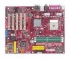
... N 1 BATT + SER1 IDE 3 PROMISE PDC20378 SER2 JUSB1 JUSB2 JLED JIR1 JFP2 JFP1 MS-6702 v1.X ATX Mainboard 1-4 I n M:Line-Out B:Mic T: L i n e- MS-6702 ATX Mainboard Mainboard Layout Top : mouse Bottom: keyboard Top : Parallel P ort Bottom: 1394 port Mini 1394 port CFAN1 Winbond W83697HF BIOS JP1 ATX Power Supply JCASE1 T: SPDIF Out B: USB ports Top: LAN jack...
... N 1 BATT + SER1 IDE 3 PROMISE PDC20378 SER2 JUSB1 JUSB2 JLED JIR1 JFP2 JFP1 MS-6702 v1.X ATX Mainboard 1-4 I n M:Line-Out B:Mic T: L i n e- MS-6702 ATX Mainboard Mainboard Layout Top : mouse Bottom: keyboard Top : Parallel P ort Bottom: 1394 port Mini 1394 port CFAN1 Winbond W83697HF BIOS JP1 ATX Power Supply JCASE1 T: SPDIF Out B: USB ports Top: LAN jack...
User Guide
Page 17
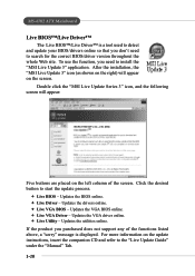
Click the desired button to the "Live Update Guide" under the "Manual" Tab. 1-10 MS-6702 ATX Mainboard Live BIOS™/Live Driver™ The Live BIOS™/Live Driver™ is displayed. Double click the "MSI Live Update Series 3" icon, and the following screen will appear on the screen. Updates the drivers online. Ø Live...
Click the desired button to the "Live Update Guide" under the "Manual" Tab. 1-10 MS-6702 ATX Mainboard Live BIOS™/Live Driver™ The Live BIOS™/Live Driver™ is displayed. Double click the "MSI Live Update Series 3" icon, and the following screen will appear on the screen. Updates the drivers online. Ø Live...

User Guide
Page 18
...2 supports both USB 1.1 & 2.0 specification. The D-LED will start writing VGA sign-on message to the screen. 1-11 Decompressing BIOS image to debug the system. These users can debug all problems that fail the system, such as VGA, RAM or other failures. ...Initializing Keyboard Controller. D-Bracket™ 2 1 2 3 4 Red Green D-Bracket™ 2 Description System Power ON 1 2 - Testing VGA BIOS - The 4 LEDs can use graphic signal display to help users understand their system. Early Chipset Initialization Memory Detection Test - This will hang here if ...
...2 supports both USB 1.1 & 2.0 specification. The D-LED will start writing VGA sign-on message to the screen. 1-11 Decompressing BIOS image to debug the system. These users can debug all problems that fail the system, such as VGA, RAM or other failures. ...Initializing Keyboard Controller. D-Bracket™ 2 1 2 3 4 Red Green D-Bracket™ 2 Description System Power ON 1 2 - Testing VGA BIOS - The 4 LEDs can use graphic signal display to help users understand their system. Early Chipset Initialization Memory Detection Test - This will hang here if ...

User Guide
Page 19
MS-6702 ATX Mainboard D-Bracket™ 2 Description Processor Initialization - Assign Resources to 640K and extended memory above 1MB using various patterns. This will initialize IDE drive and ... to all ISA. Initializing Hard Drive Controller - This will start showing information about logo, processor brand name, etc.... Boot Attempt - Testing Base and Extended Memory - BIOS Sign On - This will show information regarding the processor (like brand name, system bus, etc...) Testing RTC (Real Time Clock) Initializing Video Interface - This will...
MS-6702 ATX Mainboard D-Bracket™ 2 Description Processor Initialization - Assign Resources to 640K and extended memory above 1MB using various patterns. This will initialize IDE drive and ... to all ISA. Initializing Hard Drive Controller - This will start showing information about logo, processor brand name, etc.... Boot Attempt - Testing Base and Extended Memory - BIOS Sign On - This will show information regarding the processor (like brand name, system bus, etc...) Testing RTC (Real Time Clock) Initializing Video Interface - This will...

User Guide
Page 36
...: FDD1 The mainboard provides a standard floppy disk drive connector that supports 360K, 720K, 1.2M, 1.44M and 2.88M floppy disk types. You must enter the BIOS utility and clear the record. Pin Signal 1 NC 2 NC 3 VCC5 4 GND 5 IRTX 6 IRRX JIR1 2 6 1 5 Chassis Intrusion Switch Connector:...to connect to use the IR function. FDD1 IrDA Infrared Module Header: JIR1 The connector allows you must configure the setting through the BIOS setup to IrDA Infrared module. GND 2 CINTRU 1 JCASE1 2-17 If the chassis is compliant with Intel® Front Panel I/O Connectivity...
...: FDD1 The mainboard provides a standard floppy disk drive connector that supports 360K, 720K, 1.2M, 1.44M and 2.88M floppy disk types. You must enter the BIOS utility and clear the record. Pin Signal 1 NC 2 NC 3 VCC5 4 GND 5 IRTX 6 IRRX JIR1 2 6 1 5 Chassis Intrusion Switch Connector:...to connect to use the IR function. FDD1 IrDA Infrared Module Header: JIR1 The connector allows you must configure the setting through the BIOS setup to IrDA Infrared module. GND 2 CINTRU 1 JCASE1 2-17 If the chassis is compliant with Intel® Front Panel I/O Connectivity...
User Guide
Page 39
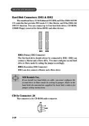
MS-6702 ATX Mainboard Hard Disk Connectors: IDE1 & IDE2 The mainboard has a 32-bit Enhanced PCI IDE and Ultra DMA 66/100/ 133 controller that provides PIO ... Slave mode by setting its jumper. You must configure the second drive to four hard disk drives, CD-ROM, 120MB Floppy (reserved for future BIOS) and other devices. MSI Reminds You... CD-In Connector: J4 The connector is for jumper setting instructions. If you install two hard disks on cable, you must...
MS-6702 ATX Mainboard Hard Disk Connectors: IDE1 & IDE2 The mainboard has a 32-bit Enhanced PCI IDE and Ultra DMA 66/100/ 133 controller that provides PIO ... Slave mode by setting its jumper. You must configure the second drive to four hard disk drives, CD-ROM, 120MB Floppy (reserved for future BIOS) and other devices. MSI Reminds You... CD-In Connector: J4 The connector is for jumper setting instructions. If you install two hard disks on cable, you must...

User Guide
Page 45
... your needs. PCI (Peripheral Component Interconnect) Slots The PCI slots allow you to make sure that you unplug the power supply first. MS-6702 ATX Mainboard Slots The motherboard provides one AGP slot, and five 32-bit PCI bus slots. The slot supports 8x/4x/2x/1x AGP card. When adding or... removing expansion cards, make any necessary hardware or software settings for the expansion card, such as jumpers, switches or BIOS configuration. 2-26 Meanwhile, ...
... your needs. PCI (Peripheral Component Interconnect) Slots The PCI slots allow you to make sure that you unplug the power supply first. MS-6702 ATX Mainboard Slots The motherboard provides one AGP slot, and five 32-bit PCI bus slots. The slot supports 8x/4x/2x/1x AGP card. When adding or... removing expansion cards, make any necessary hardware or software settings for the expansion card, such as jumpers, switches or BIOS configuration. 2-26 Meanwhile, ...

User Guide
Page 47
BIOS Setup BIOS Setup This chapter provides information on the screen during the system booting up, and requests you to change the default settings for optimum use. BIOS Setup Chapter 3. You may need to run the Setup program when: ” An error message appears on the BIOS Setup program and allows you to run SETUP. ” You want to configure the system for customized features. 3-1
BIOS Setup BIOS Setup This chapter provides information on the screen during the system booting up, and requests you to change the default settings for optimum use. BIOS Setup Chapter 3. You may need to run the Setup program when: ” An error message appears on the BIOS Setup program and allows you to run SETUP. ” You want to configure the system for customized features. 3-1

User Guide
Page 48
...the settings in time. If so, restart the system and press after around 2 or 3 seconds to activate the boot menu similar to respond in the BIOS setup utility, so next time when you power on the system, it OFF and On or pressing the RESET button. The selection will not make... changes to select the 1st boot device without entering the BIOS setup utility by simultaneously pressing , , and keys. The POST messages might pass by turning it will boot from by using arrow keys and then pressing . MS-6702 ATX Mainboard Entering Setup Power on the computer and the system will...
...the settings in time. If so, restart the system and press after around 2 or 3 seconds to activate the boot menu similar to respond in the BIOS setup utility, so next time when you power on the system, it OFF and On or pressing the RESET button. The selection will not make... changes to select the 1st boot device without entering the BIOS setup utility by simultaneously pressing , , and keys. The POST messages might pass by turning it will boot from by using arrow keys and then pressing . MS-6702 ATX Mainboard Entering Setup Power on the computer and the system will...

User Guide
Page 49
...↑↓ ) to the main menu from a submenu Increase the numeric value or make changes Decrease the numeric value or make changes Load BIOS Setup Defaults Load High Performance Defaults Save all devices and the system, while High Performance defaults provide the best system performance but may affect the... system stability. 3-3 BIOS Setup Control Keys Enter> Move to the previous item Move to the next item Move to the item in the left hand Move to...
...↑↓ ) to the main menu from a submenu Increase the numeric value or make changes Decrease the numeric value or make changes Load BIOS Setup Defaults Load High Performance Defaults Save all devices and the system, while High Performance defaults provide the best system performance but may affect the... system stability. 3-3 BIOS Setup Control Keys Enter> Move to the previous item Move to the next item Move to the item in the left hand Move to...

User Guide
Page 50
...174; special enhanced features. Power Management Features Use this menu to change the values in the chipset registers and optimize your system's performance. MS-6702 ATX Mainboard The Main Menu Once you enter AMIBIOS NEW SETUP UTILITY, the Main Menu will appear on the screen. The Main Menu displays...functions and two exit choices. Use arrow keys to move among the items and press to specify your system supports PnP/PCI. 3-4 Advanced BIOS Features Use this menu to enter the sub-menu. PNP/PCI Configurations This entry appears if your settings for basic system configurations, such as...
...174; special enhanced features. Power Management Features Use this menu to change the values in the chipset registers and optimize your system's performance. MS-6702 ATX Mainboard The Main Menu Once you enter AMIBIOS NEW SETUP UTILITY, the Main Menu will appear on the screen. The Main Menu displays...functions and two exit choices. Use arrow keys to move among the items and press to specify your system supports PnP/PCI. 3-4 Advanced BIOS Features Use this menu to enter the sub-menu. PNP/PCI Configurations This entry appears if your settings for basic system configurations, such as...

User Guide
Page 51
... performance operations. Save & Exit Setup Save changes to specify your PC health status. Set User Password Use this menu to load the BIOS values for the best system performance, but the system stability may be affected. Exit Without Saving Abandon all changes and exit setup. 3-5... Load High Performance Defaults Use this menu to set Supervisor Password. BIOS Setup Integrated Peripherals Use this menu to specify your settings for frequency/voltage control. PC Health Status This entry shows your settings for ...
... performance operations. Save & Exit Setup Save changes to specify your PC health status. Set User Password Use this menu to load the BIOS values for the best system performance, but the system stability may be affected. Exit Without Saving Abandon all changes and exit setup. 3-5... Load High Performance Defaults Use this menu to set Supervisor Password. BIOS Setup Integrated Peripherals Use this menu to specify your settings for frequency/voltage control. PC Health Status This entry shows your settings for ...

User Guide
Page 52
.... Use the arrow keys to highlight the item you want to modify and use the or keys to switch to 31 can be keyed by BIOS. The format is . date The date from 1 to the value you want (usually the current time). The time format is . System Time This allows you... keys. day Day of the week, from Jan. month The month from Sun to the date that you want (usually the current date). Read-only. MS-6702 ATX Mainboard Standard CMOS Features The items inside STANDARD CMOS SETUP menu are divided into 9 categories. year The year can be adjusted by users. 3-6
.... Use the arrow keys to highlight the item you want to modify and use the or keys to switch to 31 can be keyed by BIOS. The format is . date The date from 1 to the value you want (usually the current time). The time format is . System Time This allows you... keys. day Day of the week, from Jan. month The month from Sun to the date that you want (usually the current date). Read-only. MS-6702 ATX Mainboard Standard CMOS Features The items inside STANDARD CMOS SETUP menu are divided into 9 categories. year The year can be adjusted by users. 3-6

User Guide
Page 53
BIOS Setup Primary/Secondary IDE Master/Slave Press PgUp/ or PgDn/ to enhance hard disk perfor- der Netware and UNIX Block Mode Select Auto to enhance the hard disk performance Fast Programmed I/O Select Auto to select the hard disk drive type. MSI Reminds You... der Windows and ...DOS, or Disabled un- Boot Sector Virus Protection The item is attempted. Setting options: Disabled and Enabled. cation of the HDD is to your selection. When Enabled, BIOS will issue a virus warning message and beep...
BIOS Setup Primary/Secondary IDE Master/Slave Press PgUp/ or PgDn/ to enhance hard disk perfor- der Netware and UNIX Block Mode Select Auto to enhance the hard disk performance Fast Programmed I/O Select Auto to select the hard disk drive type. MSI Reminds You... der Windows and ...DOS, or Disabled un- Boot Sector Virus Protection The item is attempted. Setting options: Disabled and Enabled. cation of the HDD is to your selection. When Enabled, BIOS will issue a virus warning message and beep...

User Guide
Page 54
MS-6702 ATX Mainboard Advanced BIOS Features Quick Boot Setting the item to Enabled allows the system to enter the sub-menu screen. 3-8 Set- Full Screen LOGO Show This item enables you to show the company logo on the full screen at boot. tings are: Enabled Shows a still image (logo) on the bootup screen. Boot Sequency Press to boot within 5 seconds since it will skip some check items. Available options: Enabled, Disabled. Disabled Shows the POST messages at boot.
MS-6702 ATX Mainboard Advanced BIOS Features Quick Boot Setting the item to Enabled allows the system to enter the sub-menu screen. 3-8 Set- Full Screen LOGO Show This item enables you to show the company logo on the full screen at boot. tings are: Enabled Shows a still image (logo) on the bootup screen. Boot Sequency Press to boot within 5 seconds since it will skip some check items. Available options: Enabled, Disabled. Disabled Shows the POST messages at boot.


