User Guide
Page 8
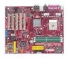
Getting Started Chapter 1. Getting Started Getting Started Thank you for digital audio transmission. The K8T Neo is based on VIA® K8T800 North Bridge & VT8237 South Bridge chipsets and provides six USB 2.0 ports for high-speed data transmission, RealTek ALC655 chip for 6-channel audio output, and a SPDIF interface for purchasing K8T Neo (MS-6702 v1.X) ATX mainboard. Designed to fit the advanced AMD® Athlon64 processors, the K8T Neo delivers a high performance and professional desktop platform solution. 1-1
Getting Started Chapter 1. Getting Started Getting Started Thank you for digital audio transmission. The K8T Neo is based on VIA® K8T800 North Bridge & VT8237 South Bridge chipsets and provides six USB 2.0 ports for high-speed data transmission, RealTek ALC655 chip for 6-channel audio output, and a SPDIF interface for purchasing K8T Neo (MS-6702 v1.X) ATX mainboard. Designed to fit the advanced AMD® Athlon64 processors, the K8T Neo delivers a high performance and professional desktop platform solution. 1-1
User Guide
Page 9
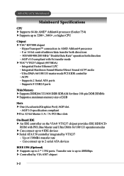
.../600/400/200 MHz "Double Data Rate" operation both direction - ACPI - HyperTransportTM connection to 2 * 1394 ports. Supports 2 Serial ATA ports - Up ot 150MB/s transfer rate - MS-6702 ATX Mainboard Mainboard Specifications CPU h Supports 64-bit AMD® Athlon64 processor (Socket 754) h Supports up to 400Mbps h Controlled by VT8237 - Transfer rate is up to 3200+, 3400...
.../600/400/200 MHz "Double Data Rate" operation both direction - ACPI - HyperTransportTM connection to 2 * 1394 ports. Supports 2 Serial ATA ports - Up ot 150MB/s transfer rate - MS-6702 ATX Mainboard Mainboard Specifications CPU h Supports 64-bit AMD® Athlon64 processor (Socket 754) h Supports up to 400Mbps h Controlled by VT8237 - Transfer rate is up to 3200+, 3400...

User Guide
Page 11
I n M:Line-Out B:Mic T: L i n e- MS-6702 ATX Mainboard Mainboard Layout Top : mouse Bottom: keyboard Top : Parallel P ort Bottom: 1394 port Mini 1394 port CFAN1 Winbond W83697HF BIOS JP1 ATX Power Supply JCASE1 T: SPDIF Out B: USB ports Top: LAN jack Bottom: USB ports T: L i n e- O u t M:Line-Out B:SPDIF Out JPW1 VIA K8T800 SFAN1 DDR 1 DDR 2 DDR 3 IDE 1 ... Slot 4 PCI Slot 5 VIA VT8237 SATA 1 SATA 2 JBAT1 JGS1 PW FA N 2 PW FA N 1 BATT + SER1 IDE 3 PROMISE PDC20378 SER2 JUSB1 JUSB2 JLED JIR1 JFP2 JFP1 MS-6702 v1.X ATX Mainboard 1-4
I n M:Line-Out B:Mic T: L i n e- MS-6702 ATX Mainboard Mainboard Layout Top : mouse Bottom: keyboard Top : Parallel P ort Bottom: 1394 port Mini 1394 port CFAN1 Winbond W83697HF BIOS JP1 ATX Power Supply JCASE1 T: SPDIF Out B: USB ports Top: LAN jack Bottom: USB ports T: L i n e- O u t M:Line-Out B:SPDIF Out JPW1 VIA K8T800 SFAN1 DDR 1 DDR 2 DDR 3 IDE 1 ... Slot 4 PCI Slot 5 VIA VT8237 SATA 1 SATA 2 JBAT1 JGS1 PW FA N 2 PW FA N 1 BATT + SER1 IDE 3 PROMISE PDC20378 SER2 JUSB1 JUSB2 JLED JIR1 JFP2 JFP1 MS-6702 v1.X ATX Mainboard 1-4

User Guide
Page 13
... select Cool'n'Quiet mode. If User mode is selected, you can detect, view and adjust the PC hardware and system status during real time operation. MS-6702 ATX Mainboard Core Center The Core Center is a new utility you will be able to adjust the CPU fan speed by sliding the adjusting bar. 1-6 The utility...
... select Cool'n'Quiet mode. If User mode is selected, you can detect, view and adjust the PC hardware and system status during real time operation. MS-6702 ATX Mainboard Core Center The Core Center is a new utility you will be able to adjust the CPU fan speed by sliding the adjusting bar. 1-6 The utility...

User Guide
Page 15
.... Diagnoses current system utilization & temperature. -- Cuts up to less noise, longer duration, more powersaving and higher performance. MS-6702 ATX Mainboard Core CellTM Chip By diagnosing the current system utilization, the CoreCell™ Chip automatically tunes your motherboard to the optimal state, leading to 65% power. -- design. -- Superior O.C. capability. -- method. LifePro -- Prevents components from operating...
.... Diagnoses current system utilization & temperature. -- Cuts up to less noise, longer duration, more powersaving and higher performance. MS-6702 ATX Mainboard Core CellTM Chip By diagnosing the current system utilization, the CoreCell™ Chip automatically tunes your motherboard to the optimal state, leading to 65% power. -- design. -- Superior O.C. capability. -- method. LifePro -- Prevents components from operating...
User Guide
Page 17
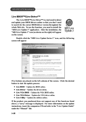
... the VGA BIOS online. Ø Live VGA Driver - If the product you don't need to install the "MSI Live Update 3" application. Updates the BIOS online. Ø Live Driver - MS-6702 ATX Mainboard Live BIOS™/Live Driver™ The Live BIOS™/Live Driver™ is a tool used to detect and... update your BIOS/drivers online so that you purchased does not support any of the screen. Double click the "MSI Live Update Series 3" icon, ...
... the VGA BIOS online. Ø Live VGA Driver - If the product you don't need to install the "MSI Live Update 3" application. Updates the BIOS online. Ø Live Driver - MS-6702 ATX Mainboard Live BIOS™/Live Driver™ The Live BIOS™/Live Driver™ is a tool used to detect and... update your BIOS/drivers online so that you purchased does not support any of the screen. Double click the "MSI Live Update Series 3" icon, ...

User Guide
Page 19
... processor (like brand name, system bus, etc...) Testing RTC (Real Time Clock) Initializing Video Interface - Boot Attempt - Testing base memory from 240K to all ISA. MS-6702 ATX Mainboard D-Bracket™ 2 Description Processor Initialization - This will initializing Floppy Drive and controller. Assign Resources to 640K and extended memory above 1MB using various patterns.
... processor (like brand name, system bus, etc...) Testing RTC (Real Time Clock) Initializing Video Interface - Boot Attempt - Testing base memory from 240K to all ISA. MS-6702 ATX Mainboard D-Bracket™ 2 Description Processor Initialization - This will initializing Floppy Drive and controller. Assign Resources to 640K and extended memory above 1MB using various patterns.

User Guide
Page 23
... power and unplug the power cord before installing the CPU. 2. If the CPU is properly and completely embedded into the socket and close the lever. MS-6702 ATX Mainboard CPU Installation Procedures for the gold arrow. Make sure to raise the lever up to make sure the CPU is correctly installed, the pins should...
... power and unplug the power cord before installing the CPU. 2. If the CPU is properly and completely embedded into the socket and close the lever. MS-6702 ATX Mainboard CPU Installation Procedures for the gold arrow. Make sure to raise the lever up to make sure the CPU is correctly installed, the pins should...

User Guide
Page 25
MS-6702 ATX Mainboard 3. Properly place the CPU onto the CPU socket . 4. Fix the retention mechanism and the backplate with two screws. 5. Position the cooling set onto the retention mechanism. retention mechanism 2-6 Locate the two screw holes of the clip to hook first. Align the retention mechanism and the backplate. Hook one end of the backplate. Turn over the mainboard again, and place the mainboard on the flat surface.
MS-6702 ATX Mainboard 3. Properly place the CPU onto the CPU socket . 4. Fix the retention mechanism and the backplate with two screws. 5. Position the cooling set onto the retention mechanism. retention mechanism 2-6 Locate the two screw holes of the clip to hook first. Align the retention mechanism and the backplate. Hook one end of the backplate. Turn over the mainboard again, and place the mainboard on the flat surface.

User Guide
Page 27
While disconnecting the Safety Hook from the fixed bolt, it is necessary to keep an eye on your fingers, because once the Safety Hook is disconnected from the fixed bolt, the fixed lever will spring back instantly. 2-8 Make sure the safety hook completely clasps the fixed bolt of the retention mechanism. Fastened down the lever. 9. MS-6702 ATX Mainboard 8. MSI Reminds You...
While disconnecting the Safety Hook from the fixed bolt, it is necessary to keep an eye on your fingers, because once the Safety Hook is disconnected from the fixed bolt, the fixed lever will spring back instantly. 2-8 Make sure the safety hook completely clasps the fixed bolt of the retention mechanism. Fastened down the lever. 9. MS-6702 ATX Mainboard 8. MSI Reminds You...
User Guide
Page 29
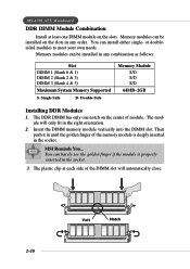
... DIMM module on the slots in any order. MSI Reminds You... You can be installed in any combination as follows: Slot DIMM 1 (Bank 0 & 1) DIMM 2 (Bank 2 & 3) DIMM 3 (Bank 4 & 5) Maximum System Memory Supported S: Single Side D: Double Side Memory Module S/D S/D S/D 64MB~2GB Installing DDR Modules 1. MS-6702 ATX Mainboard DDR DIMM Module Combination Install at each side of...
... DIMM module on the slots in any order. MSI Reminds You... You can be installed in any combination as follows: Slot DIMM 1 (Bank 0 & 1) DIMM 2 (Bank 2 & 3) DIMM 3 (Bank 4 & 5) Maximum System Memory Supported S: Single Side D: Double Side Memory Module S/D S/D S/D 64MB~2GB Installing DDR Modules 1. MS-6702 ATX Mainboard DDR DIMM Module Combination Install at each side of...

User Guide
Page 31
.... MS-6702 ATX Mainboard Back Panel The back panel provides the following connectors: Mouse Parallel SPDIF Out Line-In Line-Out MIC LAN Keyboard COM A 1394 Mini Port 1394 Port USB Ports Rear Speaker-Out Center/Subwoofer Speaker-Out SPDIF-Out Mouse Connector The mainboard provides... a standard PS/2® mouse mini DIN connector for attaching a PS/2® keyboard. Keyboard Connector The mainboard provides a standard PS/2® keyboard mini DIN connector for attaching a PS/2&#...
.... MS-6702 ATX Mainboard Back Panel The back panel provides the following connectors: Mouse Parallel SPDIF Out Line-In Line-Out MIC LAN Keyboard COM A 1394 Mini Port 1394 Port USB Ports Rear Speaker-Out Center/Subwoofer Speaker-Out SPDIF-Out Mouse Connector The mainboard provides... a standard PS/2® mouse mini DIN connector for attaching a PS/2® keyboard. Keyboard Connector The mainboard provides a standard PS/2® keyboard mini DIN connector for attaching a PS/2&#...

User Guide
Page 33
... Transmit Data Data Terminal Ready) Ground Data Set Ready Request To Send Clear To Send Ring Indicate RJ-45 LAN Jack (Optional) The mainboard provides one 9-pin male DIN connectors as serial port COM A. MS-6702 ATX Mainboard Serial Port Connectors: COM A The mainboard offers one standard RJ-45 jack for connection to the LAN jack.
... Transmit Data Data Terminal Ready) Ground Data Set Ready Request To Send Clear To Send Ring Indicate RJ-45 LAN Jack (Optional) The mainboard provides one 9-pin male DIN connectors as serial port COM A. MS-6702 ATX Mainboard Serial Port Connectors: COM A The mainboard offers one standard RJ-45 jack for connection to the LAN jack.
User Guide
Page 35
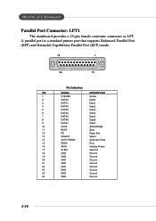
MS-6702 ATX Mainboard Parallel Port Connector: LPT1 The mainboard provides a 25-pin female centronic connector as LPT. A parallel port is a standard printer port that supports Enhanced Parallel Port (EPP) and Extended Capabilities Parallel Port (...
MS-6702 ATX Mainboard Parallel Port Connector: LPT1 The mainboard provides a 25-pin female centronic connector as LPT. A parallel port is a standard printer port that supports Enhanced Parallel Port (EPP) and Extended Capabilities Parallel Port (...
User Guide
Page 37
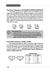
... the wire to the connectors, always take note that you must use a specially designed fan with speed sensor to GND. This mainboard has a System Hardware Monitor chipset on-board, so that the red wire is the positive and should be connected to the +12V...SENSOR PWFAN2 MSI Reminds You... 1. You can install Core Center utility that are compliant with +12V. Front USB Connectors: JUSB1 / JUSB2 The mainboard provides two USB 2.0 pin headers USB1 & USB2 that will automatically control the CPU fan speed according to a maximum throughput of the CPU fan control. MS-6702 ATX Mainboard Fan ...
... the wire to the connectors, always take note that you must use a specially designed fan with speed sensor to GND. This mainboard has a System Hardware Monitor chipset on-board, so that the red wire is the positive and should be connected to the +12V...SENSOR PWFAN2 MSI Reminds You... 1. You can install Core Center utility that are compliant with +12V. Front USB Connectors: JUSB1 / JUSB2 The mainboard provides two USB 2.0 pin headers USB1 & USB2 that will automatically control the CPU fan speed according to a maximum throughput of the CPU fan control. MS-6702 ATX Mainboard Fan ...
User Guide
Page 39
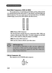
... setting its jumper. CD-In Connector: J4 The connector is for future BIOS) and other devices. J4 R GND L 2-20 MS-6702 ATX Mainboard Hard Disk Connectors: IDE1 & IDE2 The mainboard has a 32-bit Enhanced PCI IDE and Ultra DMA 66/100/ 133 controller that provides PIO mode 0~5, Bus Master, and Ultra... DMA 66/ 100/133 function. MSI Reminds You... Refer to Slave mode by hard disk vendors for jumper setting instructions. ...
... setting its jumper. CD-In Connector: J4 The connector is for future BIOS) and other devices. J4 R GND L 2-20 MS-6702 ATX Mainboard Hard Disk Connectors: IDE1 & IDE2 The mainboard has a 32-bit Enhanced PCI IDE and Ultra DMA 66/100/ 133 controller that provides PIO mode 0~5, Bus Master, and Ultra... DMA 66/ 100/133 function. MSI Reminds You... Refer to Slave mode by hard disk vendors for jumper setting instructions. ...
User Guide
Page 41
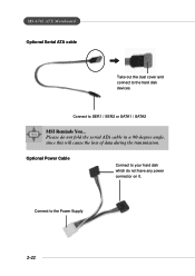
Please do not have any power connector on it. Connect to SER1 / SER2 or SATA1 / SATA2 MSI Reminds You... Optional Power Cable Connect to your hard disk which do not fold the serial ATA cable in a 90-degree angle, since this will cause the loss of data during the transmission. MS-6702 ATX Mainboard Optional Serial ATA cable Take out the dust cover and connect to the hard disk devices Connect to the Power Supply 2-22
Please do not have any power connector on it. Connect to SER1 / SER2 or SATA1 / SATA2 MSI Reminds You... Optional Power Cable Connect to your hard disk which do not fold the serial ATA cable in a 90-degree angle, since this will cause the loss of data during the transmission. MS-6702 ATX Mainboard Optional Serial ATA cable Take out the dust cover and connect to the hard disk devices Connect to the Power Supply 2-22

User Guide
Page 43
... (high for you to connect to JUSB2 (the USB pinheader in YELLOW color) LEDs 2-24 D-Bracket™ 2 is a USB Bracket that supports both USB1.1 & 2. 0 spec. MS-6702 ATX Mainboard D-Bracket™ 2 Connector: JLED (Optional) The mainboard comes with a JLED connector for red color) 9 Key 10 NC Connected to JLED D-Bracket™ 2 Connected to DBracket™ 2.
... (high for you to connect to JUSB2 (the USB pinheader in YELLOW color) LEDs 2-24 D-Bracket™ 2 is a USB Bracket that supports both USB1.1 & 2. 0 spec. MS-6702 ATX Mainboard D-Bracket™ 2 Connector: JLED (Optional) The mainboard comes with a JLED connector for red color) 9 Key 10 NC Connected to JLED D-Bracket™ 2 Connected to DBracket™ 2.

User Guide
Page 45
... is an interface specification designed for the expansion card to insert the AGP graphics card. The slot supports 8x/4x/2x/1x AGP card. MS-6702 ATX Mainboard Slots The motherboard provides one AGP slot, and five 32-bit PCI bus slots. AGP Slot PCI Slots AGP (Accelerated Graphics Port) Slot The AGP slot allows...
... is an interface specification designed for the expansion card to insert the AGP graphics card. The slot supports 8x/4x/2x/1x AGP card. MS-6702 ATX Mainboard Slots The motherboard provides one AGP slot, and five 32-bit PCI bus slots. AGP Slot PCI Slots AGP (Accelerated Graphics Port) Slot The AGP slot allows...

User Guide
Page 48
... On Self Test) process. The system will list all the bootable devices. When the message below appears on the screen, press key to enter Setup. MS-6702 ATX Mainboard Entering Setup Power on the computer and the system will not make changes to the settings in the BIOS setup utility, so next time when...
... On Self Test) process. The system will list all the bootable devices. When the message below appears on the screen, press key to enter Setup. MS-6702 ATX Mainboard Entering Setup Power on the computer and the system will not make changes to the settings in the BIOS setup utility, so next time when...


