User Guide
Page 5
... 1-2 Mainboard Layout 1-4 MSI Special Features 1-5 Color Management 1-5 Core Center 1-6 Core Cell™ Chip 1-8 Dynamic Overclocking Technology 1-9 Live BIOS™/Live Driver 1-10 D-Bracket™ 2 (Optional 1-11 Chapter 2. Hardware Setup 2-1 Quick Components Guide 2-2 Central Processing Unit: CPU 2-3 CPU Installation Procedures for Socket 754 2-4 Installing AMD Athlon64 CPU Cooler Set 2-5 Memory 2-9 Introduction to DDR...
... 1-2 Mainboard Layout 1-4 MSI Special Features 1-5 Color Management 1-5 Core Center 1-6 Core Cell™ Chip 1-8 Dynamic Overclocking Technology 1-9 Live BIOS™/Live Driver 1-10 D-Bracket™ 2 (Optional 1-11 Chapter 2. Hardware Setup 2-1 Quick Components Guide 2-2 Central Processing Unit: CPU 2-3 CPU Installation Procedures for Socket 754 2-4 Installing AMD Athlon64 CPU Cooler Set 2-5 Memory 2-9 Introduction to DDR...
User Guide
Page 9
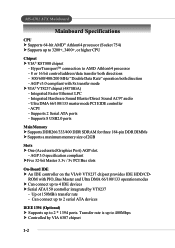
...IDE HDD/CD- HyperTransportTM connection to 4 IDE devices h Serial ATA/150 controller integrated by VIA 6307 chipset 1-2 Supports 2 Serial ATA ports - MS-6702 ATX Mainboard Mainboard Specifications CPU h Supports 64-bit AMD® Athlon64 processor (Socket 754) h Supports up to 2 * 1394 ports. Ultra... DMA 66/100/133 master mode PCI EIDE controller - Supports 8 USB2.0 ports Main Memory h Supports DDR266/333/400 DDR SDRAM for three 184-pin DDR DIMMs h Supports a maximum memory size of 2GB Slots h One (Accelerated Graphics Port) AGP slot. - Up ot 150MB/s transfer...
...IDE HDD/CD- HyperTransportTM connection to 4 IDE devices h Serial ATA/150 controller integrated by VIA 6307 chipset 1-2 Supports 2 Serial ATA ports - MS-6702 ATX Mainboard Mainboard Specifications CPU h Supports 64-bit AMD® Athlon64 processor (Socket 754) h Supports up to 2 * 1394 ports. Ultra... DMA 66/100/133 master mode PCI EIDE controller - Supports 8 USB2.0 ports Main Memory h Supports DDR266/333/400 DDR SDRAM for three 184-pin DDR DIMMs h Supports a maximum memory size of 2GB Slots h One (Accelerated Graphics Port) AGP slot. - Up ot 150MB/s transfer...

User Guide
Page 12
... ATA133 connector Serial ATA connectors Front Panel connector JFP1 Front Panel connector JFP2 1-5 Getting Started MSI Special Features Color Management MSI has a unified color management rule for some connectors on the mainboards, which helps you to install the memory modules, expansion cards and other peripherals devices more easily and conveniently. h Front panel connector...
... ATA133 connector Serial ATA connectors Front Panel connector JFP1 Front Panel connector JFP2 1-5 Getting Started MSI Special Features Color Management MSI has a unified color management rule for some connectors on the mainboards, which helps you to install the memory modules, expansion cards and other peripherals devices more easily and conveniently. h Front panel connector...

User Guide
Page 14
Left-side: Current system status In the left sub-menu, you can configure the settings of FSB, Vcore, Memory Voltage and AGP Voltage by clicking the radio button in the left and right sides. Also you may click Default to restore the default values. ...
Left-side: Current system status In the left sub-menu, you can configure the settings of FSB, Vcore, Memory Voltage and AGP Voltage by clicking the radio button in the left and right sides. Also you may click Default to restore the default values. ...

User Guide
Page 18
... LEDs, which use the feature to detect if there are any problems or failures. Early Chipset Initialization Memory Detection Test - Initializing Keyboard Controller. This will hang if the memory module is damaged or not installed properly. These users can debug all problems that fail the system, ...such as VGA, RAM or other failures. Testing onboard memory size. Decompressing BIOS image to help users understand their system. The 4 LEDs can use graphic signal display to RAM for the overclocking users...
... LEDs, which use the feature to detect if there are any problems or failures. Early Chipset Initialization Memory Detection Test - Initializing Keyboard Controller. This will hang if the memory module is damaged or not installed properly. These users can debug all problems that fail the system, ...such as VGA, RAM or other failures. Testing onboard memory size. Decompressing BIOS image to help users understand their system. The 4 LEDs can use graphic signal display to RAM for the overclocking users...

User Guide
Page 19
... - This will set low stack and boot via INT 19h. Then, detect and initialize the video adapter. Testing base memory from 240K to all ISA. Initializing Hard Drive Controller - Boot Attempt - This will show information regarding the processor (like......) Testing RTC (Real Time Clock) Initializing Video Interface - Operating System Booting 1-12 Testing Base and Extended Memory - This will initializing Floppy Drive and controller. MS-6702 ATX Mainboard D-Bracket™ 2 Description Processor Initialization - This will start showing information about logo, processor brand...
... - This will set low stack and boot via INT 19h. Then, detect and initialize the video adapter. Testing base memory from 240K to all ISA. Initializing Hard Drive Controller - Boot Attempt - This will show information regarding the processor (like......) Testing RTC (Real Time Clock) Initializing Video Interface - Operating System Booting 1-12 Testing Base and Extended Memory - This will initializing Floppy Drive and controller. MS-6702 ATX Mainboard D-Bracket™ 2 Description Processor Initialization - This will start showing information about logo, processor brand...

User Guide
Page 20
While doing the installation, be careful in holding the components and follow the installation procedures. 2-1 Hardware Setup Hardware Setup This chapter tells you how to setup the jumpers on connecting the peripheral devices, such as how to install the CPU, memory modules, and expansion cards, as well as the mouse, keyboard, etc. Hardware Setup Chapter 2. Also, it provides the instructions on the mainboard.
While doing the installation, be careful in holding the components and follow the installation procedures. 2-1 Hardware Setup Hardware Setup This chapter tells you how to setup the jumpers on connecting the peripheral devices, such as how to install the CPU, memory modules, and expansion cards, as well as the mouse, keyboard, etc. Hardware Setup Chapter 2. Also, it provides the instructions on the mainboard.

User Guide
Page 22
... the CPU, make sure the cooling fan can maximize the system performance. *Please Refer to ensure the safety of supported memory for easy CPU installation. MSI Reminds You... However, please make sure your dealer to purchase and install them before turning on the top to tolerate such...DIMM3 OK OK OK OK OK OK OK OK OK* Note: Plugging memories in DIMM1 and DIMM2 can work properly to protect the CPU from grounded outlet first to the list of CPU. Overclocking This motherboard is designed to operate beyond product specifications. 2-3 Any attempt to support ...
... the CPU, make sure the cooling fan can maximize the system performance. *Please Refer to ensure the safety of supported memory for easy CPU installation. MSI Reminds You... However, please make sure your dealer to purchase and install them before turning on the top to tolerate such...DIMM3 OK OK OK OK OK OK OK OK OK* Note: Plugging memories in DIMM1 and DIMM2 can work properly to protect the CPU from grounded outlet first to the list of CPU. Overclocking This motherboard is designed to operate beyond product specifications. 2-3 Any attempt to support ...

User Guide
Page 28
... is similar to 2GB. It uses 2.5 volts as opposed to 3.3 volts used by transferring data twice per cycle. Hardware Setup Memory The mainboard provides 3 slots for high performance PC, workstations and servers. 2-9 High memory bandwidth makes DDR an ideal solution for 184-pin DDR SDRAM DIMM (Double In-Line... Memory Module) modules and supports the memory size up to conventional SDRAM, but doubles the rate by SDR SDRAM. Plugging memories in SDR SDRAM, and requires 184-pin DIMM modules rather than 168-pin DIMM ...
... is similar to 2GB. It uses 2.5 volts as opposed to 3.3 volts used by transferring data twice per cycle. Hardware Setup Memory The mainboard provides 3 slots for high performance PC, workstations and servers. 2-9 High memory bandwidth makes DDR an ideal solution for 184-pin DDR SDRAM DIMM (Double In-Line... Memory Module) modules and supports the memory size up to conventional SDRAM, but doubles the rate by SDR SDRAM. Plugging memories in SDR SDRAM, and requires 184-pin DIMM modules rather than 168-pin DIMM ...
User Guide
Page 29
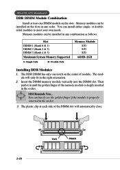
...memory module vertically into the DIMM slot. The plastic clip at least one notch on the slots. Memory...memory module is properly inserted in the socket. 3. The module will automatically close. 2-10 Volt Notch MS-6702... ATX Mainboard DDR DIMM Module Combination Install at each side of the DIMM slot will only fit in the right orientation. 2. You can be installed in any combination as follows: Slot DIMM 1 (Bank 0 & 1) DIMM 2 (Bank 2 & 3) DIMM 3 (Bank 4 & 5) Maximum System Memory... Supported S: Single Side D: Double Side Memory Module S/D S/D S/D ...
...memory module vertically into the DIMM slot. The plastic clip at least one notch on the slots. Memory...memory module is properly inserted in the socket. 3. The module will automatically close. 2-10 Volt Notch MS-6702... ATX Mainboard DDR DIMM Module Combination Install at each side of the DIMM slot will only fit in the right orientation. 2. You can be installed in any combination as follows: Slot DIMM 1 (Bank 0 & 1) DIMM 2 (Bank 2 & 3) DIMM 3 (Bank 4 & 5) Maximum System Memory... Supported S: Single Side D: Double Side Memory Module S/D S/D S/D ...

User Guide
Page 45
... expansion cards, make any necessary hardware or software settings for the expansion card to directly access main memory. It introduces a 66MHz, 32-bit channel for the throughput demands of 3D graphics. MS-6702 ATX Mainboard Slots The motherboard provides one AGP slot, and five 32-bit PCI bus slots. PCI (Peripheral Component Interconnect) Slots...
... expansion cards, make any necessary hardware or software settings for the expansion card to directly access main memory. It introduces a 66MHz, 32-bit channel for the throughput demands of 3D graphics. MS-6702 ATX Mainboard Slots The motherboard provides one AGP slot, and five 32-bit PCI bus slots. PCI (Peripheral Component Interconnect) Slots...

User Guide
Page 56
... below: Option Disabled Enabled Cached Description The specified ROM is much faster than conventional DRAM (system memory). Setting options: Enabled, Disabled. The contents of specified ROM are handled. MS-6702 ATX Mainboard Boot To OS/2 This allows you to run the OS/2® operating system with ...DRAM larger than 64MB. Internal Cache Cache memory is additional memory that is not copied to RAM for even faster access by...
... below: Option Disabled Enabled Cached Description The specified ROM is much faster than conventional DRAM (system memory). Setting options: Enabled, Disabled. The contents of specified ROM are handled. MS-6702 ATX Mainboard Boot To OS/2 This allows you to run the OS/2® operating system with ...DRAM larger than 64MB. Internal Cache Cache memory is additional memory that is not copied to RAM for even faster access by...

User Guide
Page 57
... two item control the utilized widths of the link's transmitter clock. Please note that memory is set to Manual in "Memclock Mode", user can place an artificial memory clock limit on the system. BIOS Setup Advanced Chipset Features MSI Reminds You... Change these settings only if you are familiar with the chipset. Setting...
... two item control the utilized widths of the link's transmitter clock. Please note that memory is set to Manual in "Memclock Mode", user can place an artificial memory clock limit on the system. BIOS Setup Advanced Chipset Features MSI Reminds You... Change these settings only if you are familiar with the chipset. Setting...

User Guide
Page 58
... insufficient time is installed in clock cycles) before DRAM refresh, refresh may fail to set the size of the next memory location to be accessed after receiving it. MS-6702 ATX Mainboard Bank Interleaving This field selects 2-bank or 4-bank interleave for the RAS to accumulate its charge before SDRAM ... takes to read command after the first address is the actual length of the transition from and write to properly generate the next memory location. This item applies only when synchronous DRAM is allowed for the installed SDRAM. Burst Length This setting allows you to determine ...
... insufficient time is installed in clock cycles) before DRAM refresh, refresh may fail to set the size of the next memory location to be accessed after receiving it. MS-6702 ATX Mainboard Bank Interleaving This field selects 2-bank or 4-bank interleave for the RAS to accumulate its charge before SDRAM ... takes to read command after the first address is the actual length of the transition from and write to properly generate the next memory location. This item applies only when synchronous DRAM is allowed for the installed SDRAM. Burst Length This setting allows you to determine ...

User Guide
Page 59
Select 4x only if your AGP card supports it. The option allows the selection of an aperture size of the PCI memory address range dedicated to AGP for the installed AGP card. AGP Fast Write This option enables or disables the AGP Fast Write feature. Select Enabled ... the graphics card without any translation. The Fast Write technology allows the CPU to write directly to the AGP without passing anything through the system memory and improves the AGP 4X speed. AGP Aperture Size This setting controls just how much system RAM can be allocated to graphics...
Select 4x only if your AGP card supports it. The option allows the selection of an aperture size of the PCI memory address range dedicated to AGP for the installed AGP card. AGP Fast Write This option enables or disables the AGP Fast Write feature. Select Enabled ... the graphics card without any translation. The Fast Write technology allows the CPU to write directly to the AGP without passing anything through the system memory and improves the AGP 4X speed. AGP Aperture Size This setting controls just how much system RAM can be allocated to graphics...
User Guide
Page 60
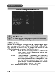
MS-6702 ATX Mainboard Power Management Features MSI Reminds You... In this state, no system context is a low power state. Auto BIOS determines the best ode automatically. 3-14 ACPI Standby State This item ... The S1 sleep mode is lost (CPU or chipset) and hardware maintains all system context. S3/STR The S3 sleep mode is saved to main memory that remains powered while most other hardware components turn off to restore the system when a "wake up" event occurs. The information stored in this field...
MS-6702 ATX Mainboard Power Management Features MSI Reminds You... In this state, no system context is a low power state. Auto BIOS determines the best ode automatically. 3-14 ACPI Standby State This item ... The S1 sleep mode is lost (CPU or chipset) and hardware maintains all system context. S3/STR The S3 sleep mode is saved to main memory that remains powered while most other hardware components turn off to restore the system when a "wake up" event occurs. The information stored in this field...

User Guide
Page 64
MS-6702 ATX Mainboard PNP/PCI Configurations This section describes configuring the PCI bus system and PnP (Plug & Play) feature. Plug and Play Aware O/S When set to ... item is set to No, BIOS will initialize all the PnP cards. Clear NVRAM The ESCD (Extended System Configuration Data) NVRAM (Non-volatile Random Access Memory) is Plug & Play. When set to the default settings. Select Yes if the operating system is where the BIOS stores resource information for booting (VGA...
MS-6702 ATX Mainboard PNP/PCI Configurations This section describes configuring the PCI bus system and PnP (Plug & Play) feature. Plug and Play Aware O/S When set to ... item is set to No, BIOS will initialize all the PnP cards. Clear NVRAM The ESCD (Extended System Configuration Data) NVRAM (Non-volatile Random Access Memory) is Plug & Play. When set to the default settings. Select Yes if the operating system is where the BIOS stores resource information for booting (VGA...

User Guide
Page 73
... set , you will be prompted to enter it every time you try to enter the password. You may also press to confirm the password. MSI Reminds You... User password: Can only enter but do not have AMIBIOS to Setup. When a password has been set password from changing any password.... You will be prompted to abort the selection and not enter a password. This prevents an unauthorized person from CMOS memory. To clear a set to Always, the password is required both at boot and at entry to request a password each time the system is ...
... set , you will be prompted to enter it every time you try to enter the password. You may also press to confirm the password. MSI Reminds You... User password: Can only enter but do not have AMIBIOS to Setup. When a password has been set password from changing any password.... You will be prompted to abort the selection and not enter a password. This prevents an unauthorized person from CMOS memory. To clear a set to Always, the password is required both at boot and at entry to request a password each time the system is ...


