
User Guide
Page 2
..., but no solution can be obtained from the user's manual, please contact your system and no guarantee is given as to make changes without notice. Netware® is a registered trademark of its contents. AMD, Athlon™, Athlon™ XP, Thoroughbred™...Support If a problem arises with your place of AMD Corporation. Copyright Notice The material in the United States and/or other information: http://global.msi.com.tw/index.php? Alternatively, please try the following help resources for FAQ, technical guide, BIOS updates, driver updates, and other countries. Visit the MSI...
..., but no solution can be obtained from the user's manual, please contact your system and no guarantee is given as to make changes without notice. Netware® is a registered trademark of its contents. AMD, Athlon™, Athlon™ XP, Thoroughbred™...Support If a problem arises with your place of AMD Corporation. Copyright Notice The material in the United States and/or other information: http://global.msi.com.tw/index.php? Alternatively, please try the following help resources for FAQ, technical guide, BIOS updates, driver updates, and other countries. Visit the MSI...
User Guide
Page 8
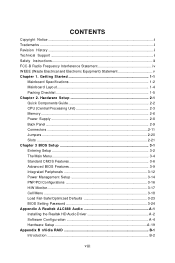
... Components Guide 2-2 CPU (Central Processing Unit 2-3 Memory ...2-6 Power Supply ...2-8 Back Panel ...2-9 Connectors ...2-11 Jumpers ...2-20 Slots ...2-21 Chapter 3 BIOS Setup 3-1 Entering Setup ...3-2 The Main Menu ...3-4 Standard CMOS Features 3-6 Advanced BIOS Features 3-9 Integrated Peripherals 3-12 Power Management Setup 3-14 PNP/PCI Configurations 3-16 H/W Monitor ...3-17 Cell Menu ...3-18 Load Fail-Safe/Optimized Defaults 3-23 BIOS Setting Password 3-24 Appendix A Realtek ALC888 Audio A-1 Installing the Realtek HD Audio Driver A-2 Software Configuration A-4 Hardware Setup...
... Components Guide 2-2 CPU (Central Processing Unit 2-3 Memory ...2-6 Power Supply ...2-8 Back Panel ...2-9 Connectors ...2-11 Jumpers ...2-20 Slots ...2-21 Chapter 3 BIOS Setup 3-1 Entering Setup ...3-2 The Main Menu ...3-4 Standard CMOS Features 3-6 Advanced BIOS Features 3-9 Integrated Peripherals 3-12 Power Management Setup 3-14 PNP/PCI Configurations 3-16 H/W Monitor ...3-17 Cell Menu ...3-18 Load Fail-Safe/Optimized Defaults 3-23 BIOS Setting Password 3-24 Appendix A Realtek ALC888 Audio A-1 Installing the Realtek HD Audio Driver A-2 Software Configuration A-4 Hardware Setup...

User Guide
Page 11
... al. p hp?func =t est report ) LAN - Supports LAN 10/100/1000 Fast Ethermet by GeForce 8100 / GeForce 8200 - t w / index. php?fu nc =c puf orm ) Supported FSB - Supports 4 pin CPU Fan Pin-Header with 360K, 720K, 1.2M, 1.44M and 2.88Mbytes Connectors Back panel - 1 PS/2 mouse port - 1 PS/2 keyboard port - 1 DVI port - 1 parallel port supporting SPP/EPP/ECP mode - 1 VGA port 1-2 AMD® Phenom/ Athlon 64/ Sempron series processors in IDE Mode) - Supports 6 SATA II devices (SATA5 and SATA6 are unavailable...
... al. p hp?func =t est report ) LAN - Supports LAN 10/100/1000 Fast Ethermet by GeForce 8100 / GeForce 8200 - t w / index. php?fu nc =c puf orm ) Supported FSB - Supports 4 pin CPU Fan Pin-Header with 360K, 720K, 1.2M, 1.44M and 2.88Mbytes Connectors Back panel - 1 PS/2 mouse port - 1 PS/2 keyboard port - 1 DVI port - 1 parallel port supporting SPP/EPP/ECP mode - 1 VGA port 1-2 AMD® Phenom/ Athlon 64/ Sempron series processors in IDE Mode) - Supports 6 SATA II devices (SATA5 and SATA6 are unavailable...

User Guide
Page 22
... pin 13 pin 12 ATX 12V Power Connector: PWR1 This 12V power connector JPW 1 is inserted in the proper orientation and the pins are connected to proper ATX power supplies to connect an ATX 24-pin power supply. PWR1 1 2 4 3 JPW1 Pin Definition PIN SIGNAL 1 GND 2 GND 3 12V 4 12V Important 1. To connect the ATX 24-pin power supply, make sure the plug of the power supply is used to provide power to avoid wrong installation. There is highly recommended for system stability. 2-8 Power supply...
... pin 13 pin 12 ATX 12V Power Connector: PWR1 This 12V power connector JPW 1 is inserted in the proper orientation and the pins are connected to proper ATX power supplies to connect an ATX 24-pin power supply. PWR1 1 2 4 3 JPW1 Pin Definition PIN SIGNAL 1 GND 2 GND 3 12V 4 12V Important 1. To connect the ATX 24-pin power supply, make sure the plug of the power supply is used to provide power to avoid wrong installation. There is highly recommended for system stability. 2-8 Power supply...
User Guide
Page 23
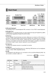
... DB15-pin female connector is for a PS/2® mouse/keyboard. Hardware Setup Back Panel Mouse Parallel Port L-In RS-Out LAN Keyboard L-Out CS-Out DVI Port VGA Port USB Ports Mic SS-Out M ouse/K ey boar d The standard PS/2® mouse/keyboard DIN connector is selected. Parallel Port A parallel port is established. You can connect a network cable to connect a LCD monitor. On (steady state) LAN link is a standard printer port that the other USB-compatible devices...
... DB15-pin female connector is for a PS/2® mouse/keyboard. Hardware Setup Back Panel Mouse Parallel Port L-In RS-Out LAN Keyboard L-Out CS-Out DVI Port VGA Port USB Ports Mic SS-Out M ouse/K ey boar d The standard PS/2® mouse/keyboard DIN connector is selected. Parallel Port A parallel port is established. You can connect a network cable to connect a LCD monitor. On (steady state) LAN link is a standard printer port that the other USB-compatible devices...

User Guide
Page 25
Hardware Setup Connectors Floppy Disk Drive Connector: FDD1 This connector supports 360KB, 720KB, 1.2MB, 1.44MB or 2.88MB floppy disk drive. IDE1 Important If you install two IDE devices on the same cable, you must configure the drives separately to IDE device's documentation supplied by setting jumpers. Refer to master / slave mode by the vendors for jumper setting instructions. 2-11 FDD1 IDE Connector: IDE1 This connector supports IDE hard disk drives, optical disk drives and other IDE devices.
Hardware Setup Connectors Floppy Disk Drive Connector: FDD1 This connector supports 360KB, 720KB, 1.2MB, 1.44MB or 2.88MB floppy disk drive. IDE1 Important If you install two IDE devices on the same cable, you must configure the drives separately to IDE device's documentation supplied by setting jumpers. Refer to master / slave mode by the vendors for jumper setting instructions. 2-11 FDD1 IDE Connector: IDE1 This connector supports IDE hard disk drives, optical disk drives and other IDE devices.
User Guide
Page 33
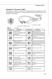
... memory above 1MB using various patterns. D-Bracket™ 2 (Optional) 1 2 DBG1 DBR1 DBG2 DBR2 DBG3 DBR3 DBG4 DBR4 Key NC 9 10 Connected to USB connector Connected to JDB1 Red Green LED Signal 1 2 3 4 Description System Power ON The D-LED will hang here if the processor is for fast booting. 3 4 1 2 Initializing Keyboard Controller. 1 2 Initializing Hard Drive Controller This will initialize IDE drive and 3 4 3 4 controller. 1 2 Testing VGA BIOS 1 2 Initializing Floppy Drive Controller This will start writing VGA sign-on This will initialize Floppy...
... memory above 1MB using various patterns. D-Bracket™ 2 (Optional) 1 2 DBG1 DBR1 DBG2 DBR2 DBG3 DBR3 DBG4 DBR4 Key NC 9 10 Connected to USB connector Connected to JDB1 Red Green LED Signal 1 2 3 4 Description System Power ON The D-LED will hang here if the processor is for fast booting. 3 4 1 2 Initializing Keyboard Controller. 1 2 Initializing Hard Drive Controller This will initialize IDE drive and 3 4 3 4 controller. 1 2 Testing VGA BIOS 1 2 Initializing Floppy Drive Controller This will start writing VGA sign-on This will initialize Floppy...
User Guide
Page 35
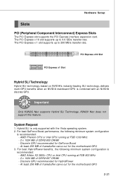
... motherboard GPU 2-21 The PCI Express x 1 slot supports up to 250 MB/s transfer rate. Important Only K9N2G Neo supports Hybird SLI Technology, K9N2V Neo does not support this feature. System Request 1. Hybrid SLI is combined with the Vista operating system. 2. Discrete GPU recommended for HybridPower - Hardware Setup Slots PCI (Peripheral Component Interconnect) Express Slots The PCI Express slot supports the PCI Express interface expansion card. At least 256 MB of DDR2-667 DRAM - AMD Phenom CPU or Intel CPU...
... motherboard GPU 2-21 The PCI Express x 1 slot supports up to 250 MB/s transfer rate. Important Only K9N2G Neo supports Hybird SLI Technology, K9N2V Neo does not support this feature. System Request 1. Hybrid SLI is combined with the Vista operating system. 2. Discrete GPU recommended for HybridPower - Hardware Setup Slots PCI (Peripheral Component Interconnect) Express Slots The PCI Express slot supports the PCI Express interface expansion card. At least 256 MB of DDR2-667 DRAM - AMD Phenom CPU or Intel CPU...

User Guide
Page 37
... signals to the microprocessor. Hardware Setup PCI (Peripheral Component Interconnect) Slots The PCI slots support LAN cards, SCSI cards, USB cards, and other add-on cards that you unplug the power supply first. PCI Interrupt Request Routing The IRQ, acronym of 133 MBps. 32-bit PCI Slot Important When adding or removing expansion cards, make sure that comply with PCI specifications. Meanwhile, read the documentation for the expansion card to the PCI bus pins as jumpers, switches or BIOS configuration.
... signals to the microprocessor. Hardware Setup PCI (Peripheral Component Interconnect) Slots The PCI slots support LAN cards, SCSI cards, USB cards, and other add-on cards that you unplug the power supply first. PCI Interrupt Request Routing The IRQ, acronym of 133 MBps. 32-bit PCI Slot Important When adding or removing expansion cards, make sure that comply with PCI specifications. Meanwhile, read the documentation for the expansion card to the PCI bus pins as jumpers, switches or BIOS configuration.
User Guide
Page 44
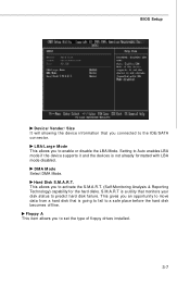
Setting to set the type of floppy drives installed. 3-7 Floppy A This item allows you to Auto enables LBA mode if the device supports it and the devices is not already formatted with LBA mode disabled. BIOS Setup Device/ Vender/ Size It will showing the device information that monitors your disk status to predict hard disk failure. LBA/Large M ode This allows you to the IDE/SATA connector. Hard Disk S.M.A.R.T. This allows you an opportunity to move data from a hard disk that is a utility that...
Setting to set the type of floppy drives installed. 3-7 Floppy A This item allows you to Auto enables LBA mode if the device supports it and the devices is not already formatted with LBA mode disabled. BIOS Setup Device/ Vender/ Size It will showing the device information that monitors your disk status to predict hard disk failure. LBA/Large M ode This allows you to the IDE/SATA connector. Hard Disk S.M.A.R.T. This allows you an opportunity to move data from a hard disk that is a utility that...
User Guide
Page 46
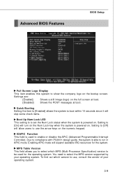
... allow users to compliance with PC2001 design guide, the system is powered on the numeric keypad. Advanced BIOS Features BIOS Setup Full Screen Logo Display This item enables this system to select the MPS version supported by your operating system. 3-9 Setting to enable or disable the APIC (Advanced Programmable Interrupt Controller). Quick Booting Setting the item to [Enabled] allows the system to boot within 10 seconds since it will turn...
... allow users to compliance with PC2001 design guide, the system is powered on the numeric keypad. Advanced BIOS Features BIOS Setup Full Screen Logo Display This item enables this system to select the MPS version supported by your operating system. 3-9 Setting to enable or disable the APIC (Advanced Programmable Interrupt Controller). Quick Booting Setting the item to [Enabled] allows the system to boot within 10 seconds since it will turn...
User Guide
Page 47
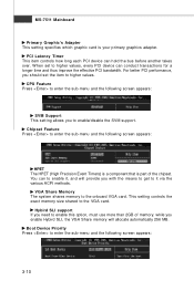
... enable this option, must use more than 2GB of the chipset. This setting controls the exact memory size shared to the onboard VGA card. MS-7511 Mainboard Primary Graphic's Adapter This setting specifies which graphic card is part of memory. For better PCI performance, you with the means to get to enable/disable the SVM support. while you to it , and will allocate automatically 256 MB. VGA Share Memory The system shares memory to the VGA card. Boot Device...
... enable this option, must use more than 2GB of the chipset. This setting controls the exact memory size shared to the onboard VGA card. MS-7511 Mainboard Primary Graphic's Adapter This setting specifies which graphic card is part of memory. For better PCI performance, you with the means to get to enable/disable the SVM support. while you to it , and will allocate automatically 256 MB. VGA Share Memory The system shares memory to the VGA card. Boot Device...

User Guide
Page 50
... allow the onboard parallel port to enable or disable the IDE controller. OnChip SATA Controller This item allows users to select mode for the 2nd serial port. If you to enable/ disable BIOS to used to enable or disable the SATA controller. Parallel Port There is used PCI busmastering for the 1st/2nd serial port. RAID Mode This item is a built-in parallel port on the on-board Super I /O Devices Configuration Press to IDE drives. To operate the onboard parallel port in ECP mode only. I /O chipset that...
... allow the onboard parallel port to enable or disable the IDE controller. OnChip SATA Controller This item allows users to select mode for the 2nd serial port. If you to enable/ disable BIOS to used to enable or disable the SATA controller. Parallel Port There is used PCI busmastering for the 1st/2nd serial port. RAID Mode This item is a built-in parallel port on the on-board Super I /O Devices Configuration Press to IDE drives. To operate the onboard parallel port in ECP mode only. I /O chipset that...

User Guide
Page 52
... PCIE Device W hen set to [Enabled], the feature allows your system will not function anymore and you choose Specific Key, the power button on state. [Last State] Restores the system to be awakened from the power saving modes through any event on the system. If you must type the password to enable or disable the feature of the power button. BIOS Setup Power Button Function This feature sets the function of booting...
... PCIE Device W hen set to [Enabled], the feature allows your system will not function anymore and you choose Specific Key, the power button on state. [Last State] Restores the system to be awakened from the power saving modes through any event on the system. If you must type the password to enable or disable the feature of the power button. BIOS Setup Power Button Function This feature sets the function of booting...

User Guide
Page 53
... users to operate at speeds nearing the speed the CPU itself uses when communicating with its special components. W hen set the item to higher values. For better PCI performance, you will be reserved for PCI bus architecture. Settings are: PCI Device For Plug & Play compatible devices designed for further request. 3-16 MS-7511 Mainboard PnP/PCI Configurations This section describes configuring the PCI bus system and PnP (Plug & Play) feature. PCI Slot 1/2/3 IRQ This setting...
... users to operate at speeds nearing the speed the CPU itself uses when communicating with its special components. W hen set the item to higher values. For better PCI performance, you will be reserved for PCI bus architecture. Settings are: PCI Device For Plug & Play compatible devices designed for further request. 3-16 MS-7511 Mainboard PnP/PCI Configurations This section describes configuring the PCI bus system and PnP (Plug & Play) feature. PCI Slot 1/2/3 IRQ This setting...

User Guide
Page 54
... temperature to [Reset]. CPU/System Temperature, CPU FAN/ SYS FAN 1/ SYS FAN 2 Speed, CPU Vcore, 3.3VCC, 5V, 12V, 3V SB These items display the current status of all fans' speeds. 3-17 The setting of the monitored hardware devices/ components such as CPU voltage, temperatures and all of the field will automatically return to [Enabled] later. To clear the warning message, set the field to keep it with in a specific range --PC Health Status-- H/W Monitor BIOS Setup Chassis...
... temperature to [Reset]. CPU/System Temperature, CPU FAN/ SYS FAN 1/ SYS FAN 2 Speed, CPU Vcore, 3.3VCC, 5V, 12V, 3V SB These items display the current status of all fans' speeds. 3-17 The setting of the monitored hardware devices/ components such as CPU voltage, temperatures and all of the field will automatically return to [Enabled] later. To clear the warning message, set the field to keep it with in a specific range --PC Health Status-- H/W Monitor BIOS Setup Chassis...
User Guide
Page 58
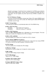
... interference (EMI). M emory Voltage Adjusting the memory voltage can increase the memory speed. Select [1T] makes SDRAM signal controller to automatically detect all of the DRAM timing. SB to CPU LinkWidth This item allows you to [Disabled], the item will remove (turn off) clocks from CPU to precharge. NB Voltage Adjust the North Bridge chipset voltage. BIOS Setup allowed to chipset. Auto Disable DIMM/PCI Frequency W hen set to increase the CPU voltage. Adjust AM D NB...
... interference (EMI). M emory Voltage Adjusting the memory voltage can increase the memory speed. Select [1T] makes SDRAM signal controller to automatically detect all of the DRAM timing. SB to CPU LinkWidth This item allows you to [Disabled], the item will remove (turn off) clocks from CPU to precharge. NB Voltage Adjust the North Bridge chipset voltage. BIOS Setup allowed to chipset. Auto Disable DIMM/PCI Frequency W hen set to increase the CPU voltage. Adjust AM D NB...
User Guide
Page 86
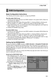
nVidia RAID RAID Configuration Basic Configuration Instructions The following are to be RAID enabled in the system BIOS. (Refer the bios section for details.) 2. Enter the W indows OS, run the W indows nForce Setup application and install the RAID software. (Check B-8 for details.) 4. Entering the RAID BIOS Setup 1. The RAID prompt appears as part of the array. B-3 Boot from the W indows CD, use the floppy disk that are to loading the OS. 2. The PC will appear. After...
nVidia RAID RAID Configuration Basic Configuration Instructions The following are to be RAID enabled in the system BIOS. (Refer the bios section for details.) 2. Enter the W indows OS, run the W indows nForce Setup application and install the RAID software. (Check B-8 for details.) 4. Entering the RAID BIOS Setup 1. The RAID prompt appears as part of the array. B-3 Boot from the W indows CD, use the floppy disk that are to loading the OS. 2. The PC will appear. After...
User Guide
Page 90
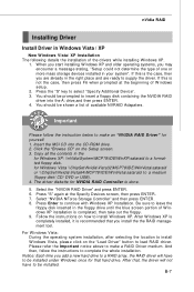
... CD-ROM drive. 2. Press "S" again at the beginning of W indows setup. 2. You should be installed. Insert the MSI CD into the A: drive,and then press ENTER. 4. After W indows XP is completely installed, it is done. 5. For W indows Vista: During the operating system installation, after selecting the location to install W indows Vista, please click on the "Load Driver" button to select "Specify Additional Device". 3. nVidia RAID Installing Driver Install Driver in Windows...
... CD-ROM drive. 2. Press "S" again at the beginning of W indows setup. 2. You should be installed. Insert the MSI CD into the A: drive,and then press ENTER. 4. After W indows XP is completely installed, it is done. 5. For W indows Vista: During the operating system installation, after selecting the location to install W indows Vista, please click on the "Load Driver" button to select "Specify Additional Device". 3. nVidia RAID Installing Driver Install Driver in Windows...

User Guide
Page 102
... enter sub-menu to make further configuration or to enable or disable the Dynamic Overclocking Technology. C-3 Dual Core Center Main Before using this utility, we have to remind you install a graphics card of other brand, only hardware status of this utility. VGA Click VGA button to read current CPU temperature, FSB and CPU clock of graphics card will show below . If you : only when installing the MSI V044 (V044 has to read current GPU temperature, GPU clock and memory clock of mainboard...
... enter sub-menu to make further configuration or to enable or disable the Dynamic Overclocking Technology. C-3 Dual Core Center Main Before using this utility, we have to remind you install a graphics card of other brand, only hardware status of this utility. VGA Click VGA button to read current CPU temperature, FSB and CPU clock of graphics card will show below . If you : only when installing the MSI V044 (V044 has to read current GPU temperature, GPU clock and memory clock of mainboard...

