
User Guide
Page 4
... work well or you can be obtained from the user's manual, please contact your system and no solution can not get the equipment checked by the manu f ac tu rer. The openings on the enclosure are for technical guide, BIOS updates, driver updates, and other information: http://www.msi.com.tw & http://www.msi. Always Unplug the Power Cord before setting it...
... work well or you can be obtained from the user's manual, please contact your system and no solution can not get the equipment checked by the manu f ac tu rer. The openings on the enclosure are for technical guide, BIOS updates, driver updates, and other information: http://www.msi.com.tw & http://www.msi. Always Unplug the Power Cord before setting it...
User Guide
Page 8
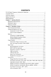
...SDRAM 2-7 Memory Module Population Rules 2-7 Installing DDRII Modules 2-8 Power Supply ...2-9 ATX 24-Pin Power Connector: ATX 2-9 ATX 12V Power Connector: JPW / JPW R 2-9 Back Panel ...2-10 Mouse/Keyboard Connector 2-10 IEEE 1394 Port (optional 2-10 Serial Port Connector: COM Port 2-11 USB Connectors 2-11 LAN (RJ-45) Jack 2-12 Audio Port Connectors 2-12 Parallel Port Connector: LPT1 2-13 Connectors ...2-14 Floppy Disk Drive Connector: FDD 2-14 Fan Power Connectors: CPU_FAN / SYS_FAN / PWR_FAN / NB_FAN 2-14 Hard Disk Connector: IDE1/ IDE2 2-15 SATAII Connectors controlled by Intel...
...SDRAM 2-7 Memory Module Population Rules 2-7 Installing DDRII Modules 2-8 Power Supply ...2-9 ATX 24-Pin Power Connector: ATX 2-9 ATX 12V Power Connector: JPW / JPW R 2-9 Back Panel ...2-10 Mouse/Keyboard Connector 2-10 IEEE 1394 Port (optional 2-10 Serial Port Connector: COM Port 2-11 USB Connectors 2-11 LAN (RJ-45) Jack 2-12 Audio Port Connectors 2-12 Parallel Port Connector: LPT1 2-13 Connectors ...2-14 Floppy Disk Drive Connector: FDD 2-14 Fan Power Connectors: CPU_FAN / SYS_FAN / PWR_FAN / NB_FAN 2-14 Hard Disk Connector: IDE1/ IDE2 2-15 SATAII Connectors controlled by Intel...
User Guide
Page 10
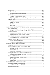
... RAID Migration Instructions 5-14 Create RAID Volume from Existing Disk 5-15 Degraded RAID Array 5-21 Missing Hard Drive Member 5-21 Failed Hard Drive Member 5-21 Chapter 6. Realtek ALC883 Introduction 7-1 Installing the Realtek HD Audio Driver 7-3 Installation for W indows 2000/XP 7-2 Software Configuration 7-4 x Intel ICH7R SATA RAID Introduction 5-1 BIOS Configuration 5-2 Using the Intel Matrix Stroage Manager Option ROM 5-2 Installing Software 5-8 Install Driver in W indows XP / 2000 6-9 JMicron Raid Configurer 6-10 Viewing RAID Array Configurations 6-10 Creating RAID...
... RAID Migration Instructions 5-14 Create RAID Volume from Existing Disk 5-15 Degraded RAID Array 5-21 Missing Hard Drive Member 5-21 Failed Hard Drive Member 5-21 Chapter 6. Realtek ALC883 Introduction 7-1 Installing the Realtek HD Audio Driver 7-3 Installation for W indows 2000/XP 7-2 Software Configuration 7-4 x Intel ICH7R SATA RAID Introduction 5-1 BIOS Configuration 5-2 Using the Intel Matrix Stroage Manager Option ROM 5-2 Installing Software 5-8 Install Driver in W indows XP / 2000 6-9 JMicron Raid Configurer 6-10 Viewing RAID Array Configurations 6-10 Creating RAID...

User Guide
Page 13
... http://www.msi.com.tw/program/ products/mainboard/mbd/pro_mbd_cpu_support.php) Chipset † Intel® 975X chipset - On-Board IDE/ SATA † One Ultra DMA 66/100 IDE controllers integrated in LGA775 package. † Support Cedar Mill Value Processor † Supports 4-pin CPU Fan pin header with SATA RAID 0, RAID 1, RAID 10, RAID 5 and Matrix RAID. 1-2 Supports 2 PCI Express x16 graphics interface (can transfer into 2 PCIE x 8 ports). † 2 PCI Express x1 slots. † 2 V2.3 Master PCI bus slots (32-bit, 3.3V/5V interface). Main Memory † Supports 4 DDRII 533...
... http://www.msi.com.tw/program/ products/mainboard/mbd/pro_mbd_cpu_support.php) Chipset † Intel® 975X chipset - On-Board IDE/ SATA † One Ultra DMA 66/100 IDE controllers integrated in LGA775 package. † Support Cedar Mill Value Processor † Supports 4-pin CPU Fan pin header with SATA RAID 0, RAID 1, RAID 10, RAID 5 and Matrix RAID. 1-2 Supports 2 PCI Express x16 graphics interface (can transfer into 2 PCIE x 8 ports). † 2 PCI Express x1 slots. † 2 V2.3 Master PCI bus slots (32-bit, 3.3V/5V interface). Main Memory † Supports 4 DDRII 533...

User Guide
Page 14
... mode - 1 Line-In / Line-Out / MIC-In / Rear Speaker Out / Center-Subwoofer Speaker Out (5 in 1) audio connector, a coaxial SPDIF-Out and a optical SPDIF-Out - 8 USB ports (Rear * 4/ Front * 4) - 1 RJ-45 LAN jack - 2 IEEE 1394 ports (rear*1/ front*1) (optional) On-board LAN †Broadcom BCM5751 - Supports ACPI Power Management. 1394 (optional) † Supports two IEEE1394 ports. Compliane with PCI 2.2. - Getting Started † One PCI Express to PATA/ SATAII Host controller integrated in Intel® ICH7R chip. † 7.1 + 2 channels audio...
... mode - 1 Line-In / Line-Out / MIC-In / Rear Speaker Out / Center-Subwoofer Speaker Out (5 in 1) audio connector, a coaxial SPDIF-Out and a optical SPDIF-Out - 8 USB ports (Rear * 4/ Front * 4) - 1 RJ-45 LAN jack - 2 IEEE 1394 ports (rear*1/ front*1) (optional) On-board LAN †Broadcom BCM5751 - Supports ACPI Power Management. 1394 (optional) † Supports two IEEE1394 ports. Compliane with PCI 2.2. - Getting Started † One PCI Express to PATA/ SATAII Host controller integrated in Intel® ICH7R chip. † 7.1 + 2 channels audio...
User Guide
Page 23
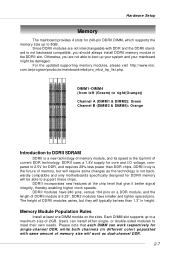
... spaced pins. Users can work as the technology is the top limit of memory, but they will require some changes as dual-channel DDR. 2-7 Please note that give it better signal integrity, thereby enabling higher clock speeds. DDRII truly is the future of current DDR technology. The height of memory module, and its speed is not backwardly compatible and only motherboards specifically designed for DDRII memory will work respectively...
... spaced pins. Users can work as the technology is the top limit of memory, but they will require some changes as dual-channel DDR. 2-7 Please note that give it better signal integrity, thereby enabling higher clock speeds. DDRII truly is the future of current DDR technology. The height of memory module, and its speed is not backwardly compatible and only motherboards specifically designed for DDRII memory will work respectively...

User Guide
Page 25
... 8 +12V 1 JPWR JPWR Pin Definition PIN SIGNAL 1 5V 2 GND 3 GND 4 12V MSI Reminds You... 1. To connect the ATX 24-pin power supply, make sure that no damage will be greater than 18A. 2-9 ATX 12V power connection should be caused. Hardware Setup Power Supply The mainboard supports ATX power supply for system stability. 3. ATX 24-Pin Power Connector: ATX This connector allows you to the CPU. And the JPWR 12V power connector is highly recommended for the power system. Power supply of the...
... 8 +12V 1 JPWR JPWR Pin Definition PIN SIGNAL 1 5V 2 GND 3 GND 4 12V MSI Reminds You... 1. To connect the ATX 24-pin power supply, make sure that no damage will be greater than 18A. 2-9 ATX 12V power connection should be caused. Hardware Setup Power Supply The mainboard supports ATX power supply for system stability. 3. ATX 24-Pin Power Connector: ATX This connector allows you to the CPU. And the JPWR 12V power connector is highly recommended for the power system. Power supply of the...

User Guide
Page 31
... install two hard disks on cable, you must configure second hard drive to the hard disk documentation supplied by hard disk vendors for jumper setting instructions. 2-15 MSI Reminds You... IDE1 (blue) IDE2 (yellow) IDE1 (Primary IDE Connector) The first hard drive should always be connected to Slave mode by setting the jumper accordingly. IDE1 can connect a Master drive. Hardware Setup Hard Disk Connector: IDE1/ IDE2 The mainboard supports 2 IDE connectors, which supports PIO & Bus Master operation modes. You must configure the second drive to IDE1. Refer to Slave mode...
... install two hard disks on cable, you must configure second hard drive to the hard disk documentation supplied by hard disk vendors for jumper setting instructions. 2-15 MSI Reminds You... IDE1 (blue) IDE2 (yellow) IDE1 (Primary IDE Connector) The first hard drive should always be connected to Slave mode by setting the jumper accordingly. IDE1 can connect a Master drive. Hardware Setup Hard Disk Connector: IDE1/ IDE2 The mainboard supports 2 IDE connectors, which supports PIO & Bus Master operation modes. You must configure the second drive to IDE1. Refer to Slave mode...

User Guide
Page 40
... other sophisticated applications. It supports 2 PCIE x 16 slots transfer into 2 PCIE x 8 ports (CrossFire Technology). The mainboard can insert the expansion cards to complete CrossFire: 1. PCI Express architecture provides a high performance I /O. To utilize this technology, always install the CrossFire Edition graphics card in the Primary PCIE x16 (PEG1) slot and install the CrossFire Ready graphics card in BIOS by ATI that you unplug the power supply first. M S-7246 ATX Mainboard Slots The mainboard provides 2 PCI Express x16 slots, 2 PCI Express x1 slots and 2 PCI bus slots.
... other sophisticated applications. It supports 2 PCIE x 16 slots transfer into 2 PCIE x 8 ports (CrossFire Technology). The mainboard can insert the expansion cards to complete CrossFire: 1. PCI Express architecture provides a high performance I /O. To utilize this technology, always install the CrossFire Edition graphics card in the Primary PCIE x16 (PEG1) slot and install the CrossFire Ready graphics card in BIOS by ATI that you unplug the power supply first. M S-7246 ATX Mainboard Slots The mainboard provides 2 PCI Express x16 slots, 2 PCI Express x1 slots and 2 PCI bus slots.

User Guide
Page 41
.... Then connectting a monitor to the monitor) DVI connector MSI Reminds You... 1. The CrossFire Edition graphics card. DMS connector DVI connector (connectting to the left DVI connector. Only Windows® XP with Service Pack 2 (SP2)& Windows® XP Profes -sional x64 Edition support the CrossFire function. 3. The cable is attached from the CrossFire Ready graphics card's DVI connector to connect the two graphics cards. Hardware Setup 2.Use the external cable to the CrossFire Edition high density input connector...
.... Then connectting a monitor to the monitor) DVI connector MSI Reminds You... 1. The CrossFire Edition graphics card. DMS connector DVI connector (connectting to the left DVI connector. Only Windows® XP with Service Pack 2 (SP2)& Windows® XP Profes -sional x64 Edition support the CrossFire function. 3. The cable is attached from the CrossFire Ready graphics card's DVI connector to connect the two graphics cards. Hardware Setup 2.Use the external cable to the CrossFire Edition high density input connector...

User Guide
Page 48
BIOS Setup Standard CMOS Features The items in Standard CMOS Features Menu includes some basic setup items. Use the arrow keys to highlight the item and then use [Manual] to set the system to select [Manual], [None] or [Auto] type. only. month The month from the keyboard. year The year can be keyed by users. Capacity The formatted size of heads. date The date from your drive must match with...
BIOS Setup Standard CMOS Features The items in Standard CMOS Features Menu includes some basic setup items. Use the arrow keys to highlight the item and then use [Manual] to set the system to select [Manual], [None] or [Auto] type. only. month The month from the keyboard. year The year can be keyed by users. Capacity The formatted size of heads. date The date from your drive must match with...

User Guide
Page 53
... be cached. Setting optoins: [ECC], [Non-ECC]. W hen this option according to the type of DRAM installed in your system: error-correcting code (ECC) or parity (default). Setting options: [Disabled], [Enabled]. M S-7246 ATX Mainboard Advanced Chipset Features System BIOS Cacheable Selecting [Enabled] allows caching of the system BIOS ROM at C0000h to C7FFFh, resulting in better video performance. However, if any program writes to this memory area, a system error may result. Setting options: [Enabled], [Disabled]. Setting options: [Enabled], [Disabled]. 3-10
... be cached. Setting optoins: [ECC], [Non-ECC]. W hen this option according to the type of DRAM installed in your system: error-correcting code (ECC) or parity (default). Setting options: [Disabled], [Enabled]. M S-7246 ATX Mainboard Advanced Chipset Features System BIOS Cacheable Selecting [Enabled] allows caching of the system BIOS ROM at C0000h to C7FFFh, resulting in better video performance. However, if any program writes to this memory area, a system error may result. Setting options: [Enabled], [Disabled]. Setting options: [Enabled], [Disabled]. 3-10

User Guide
Page 55
...-menu and the following screen appears: Onboard FDC Controller Select [Enabled] if your system has a floppy disk controller (FDC) installed on the system board and you install add-on FDC or the system has no floppy drive, select [Disabled] in parallel port on the on the screen: "EPP Mode Select." COM Port Select an address and corresponding interrupt for the onboard parallel port. At this field. IO Devices Configuration Press to use it. Setting options...
...-menu and the following screen appears: Onboard FDC Controller Select [Enabled] if your system has a floppy disk controller (FDC) installed on the system board and you install add-on FDC or the system has no floppy drive, select [Disabled] in parallel port on the on the screen: "EPP Mode Select." COM Port Select an address and corresponding interrupt for the onboard parallel port. At this field. IO Devices Configuration Press to use it. Setting options...

User Guide
Page 56
... channel [3] or [1]. If your IDE hard drive supports block mode (most new drives do), select [Enabled] for automatic detection of the optimal number of the four IDE devices that the IDE controller on the PCI local bus has bus mastering capability. Choose [Enabled] to enter the sub-menu and the following message will appear: "ECP Mode Use DMA." IDE Devices Configuration Press to activate the channel. Settings options: [Disabled], [Enabled]. BIOS Setup ECP Mode Use DMA The ECP mode has to use the DMA channel...
... channel [3] or [1]. If your IDE hard drive supports block mode (most new drives do), select [Enabled] for automatic detection of the optimal number of the four IDE devices that the IDE controller on the PCI local bus has bus mastering capability. Choose [Enabled] to enter the sub-menu and the following message will appear: "ECP Mode Use DMA." IDE Devices Configuration Press to activate the channel. Settings options: [Disabled], [Enabled]. BIOS Setup ECP Mode Use DMA The ECP mode has to use the DMA channel...

User Guide
Page 57
... the setting options of On-Chip Serial ATA, select [Disabled] if you to select the parallel ATA channel. Select [AHCI] to allow you to select the compatible SATA Spec version. Setting options: [Disabled], [Force GEN I], [Force GEN II]. Setting options: [IDE], [AHCI], [RAID]. Refer to let the system arrange automatically. SATA Port This feature allows users to 4 devices. M S-7246 ATX Mainboard SATA Devices Configuration Press to enter the sub-menu and the following tables for details. Select [Combined Mode] to use all SATA controllers.
... the setting options of On-Chip Serial ATA, select [Disabled] if you to select the parallel ATA channel. Select [AHCI] to allow you to select the compatible SATA Spec version. Setting options: [Disabled], [Force GEN I], [Force GEN II]. Setting options: [IDE], [AHCI], [RAID]. Refer to let the system arrange automatically. SATA Port This feature allows users to 4 devices. M S-7246 ATX Mainboard SATA Devices Configuration Press to enter the sub-menu and the following tables for details. Select [Combined Mode] to use all SATA controllers.

User Guide
Page 66
... x 2). Auto Detect PCI Clk This item is adjustable in MHz) and overclock the processor by adjusting the FSB clock to a higher frequency. Read only. M emory Voltage Adjusting the memory voltage can increase the memory speed. BIOS Setup FSB & Memory Clock Ratio These settings control the ratio of FSB Clock and Memory Clock to enable the CPU & Memory to increase the performance of your PCI Express card when overclocking, but the stability may cause a stability issue, so changing the memory voltage...
... x 2). Auto Detect PCI Clk This item is adjustable in MHz) and overclock the processor by adjusting the FSB clock to a higher frequency. Read only. M emory Voltage Adjusting the memory voltage can increase the memory speed. BIOS Setup FSB & Memory Clock Ratio These settings control the ratio of FSB Clock and Memory Clock to enable the CPU & Memory to increase the performance of your PCI Express card when overclocking, but the stability may cause a stability issue, so changing the memory voltage...
User Guide
Page 82
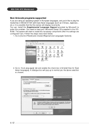
... box will display incorrectly. You need to the [Languages] tab and enable the check box of [Install files for East Asian languages]. You can install the Supplemental Language Support provided by Microsoft to [Control Panel] and choose [Regional and Languages Options]. 2. M S-7246MASTI XFeMaatuinreboard Non-Unicode programs supported If you are configured here. etc.), it is chosen. 4-12 Go to solve this problem.
... box will display incorrectly. You need to the [Languages] tab and enable the check box of [Install files for East Asian languages]. You can install the Supplemental Language Support provided by Microsoft to [Control Panel] and choose [Regional and Languages Options]. 2. M S-7246MASTI XFeMaatuinreboard Non-Unicode programs supported If you are configured here. etc.), it is chosen. 4-12 Go to solve this problem.

User Guide
Page 90
... Stroage Manager Option ROM is only available with a supported Intel chipset. Also, you are reinstalling your system. The "Driver Model", "Serial #" and "Size" in BIOS (please refer to "Chapter 3" SATA Mode for details) to enter the RAID Configuration Utility. M S-7246 ATX M ainboard BIOS Configuration The Intel Matrix Storage Manager Option ROM should be integrated with the system BIOS on all motherboards with a newly-built system or if you need to enable the RAID function in...
... Stroage Manager Option ROM is only available with a supported Intel chipset. Also, you are reinstalling your system. The "Driver Model", "Serial #" and "Size" in BIOS (please refer to "Chapter 3" SATA Mode for details) to enter the RAID Configuration Utility. M S-7246 ATX M ainboard BIOS Configuration The Intel Matrix Storage Manager Option ROM should be integrated with the system BIOS on all motherboards with a newly-built system or if you need to enable the RAID function in...
User Guide
Page 96
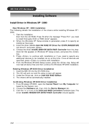
... SATAII RAID Controller should appear. 5-8 Insert the driver diskette Intel IAA RAID XP Driver For ICH7R (NH82801GR) into the CD-ROM drive. 2. Click the "+" in Windows XP / 2000 † New Windows XP / 2000 Installation The following details the installation of the SCSI and RAID Controllers hardware type. M S-7246 ATX M ainboard Installing Software Install Driver in front of the drivers while installing W indows XP / 2000. 1. Choose the driver Intel(R) 82801GR SATA RAID Controller from the dropdown list...
... SATAII RAID Controller should appear. 5-8 Insert the driver diskette Intel IAA RAID XP Driver For ICH7R (NH82801GR) into the CD-ROM drive. 2. Click the "+" in Windows XP / 2000 † New Windows XP / 2000 Installation The following details the installation of the SCSI and RAID Controllers hardware type. M S-7246 ATX M ainboard Installing Software Install Driver in front of the drivers while installing W indows XP / 2000. 1. Choose the driver Intel(R) 82801GR SATA RAID Controller from the dropdown list...
User Guide
Page 119
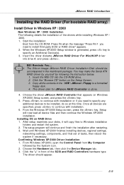
... be accompanied in the \\IDE \ JMicron \ Floppy to specify an Additional Device(s). 3. JMicron RAID Introduction Installing the RAID Driver (For bootable RAID array) Install Driver in front of the SCSI and RAID Controllers hardware type. Insert the driver diskette JMicron RAID Driver For Win2K/XP driver into the CD-ROM drive. 2. Click the "Browse CD" botton on W indows XP/2000 Setup screen, and press the key. 5. Once all device files and then continue the...
... be accompanied in the \\IDE \ JMicron \ Floppy to specify an Additional Device(s). 3. JMicron RAID Introduction Installing the RAID Driver (For bootable RAID array) Install Driver in front of the SCSI and RAID Controllers hardware type. Insert the driver diskette JMicron RAID Driver For Win2K/XP driver into the CD-ROM drive. 2. Click the "Browse CD" botton on W indows XP/2000 Setup screen, and press the key. 5. Once all device files and then continue the...

