
User Guide
Page 1
... frequency energy and, if not installed and used in order to provide reasonable protection against harmful interference in a residential installation. n Connect the equipment into an outlet on , the user is connected. n Consult the dealer or an experienced radio/ television technician for a class B digital device, pursuant to part 15 of the measures listed below. Notice 2 Shielded interface cables and A.C. This equipment generates, uses...
... frequency energy and, if not installed and used in order to provide reasonable protection against harmful interference in a residential installation. n Connect the equipment into an outlet on , the user is connected. n Consult the dealer or an experienced radio/ television technician for a class B digital device, pursuant to part 15 of the measures listed below. Notice 2 Shielded interface cables and A.C. This equipment generates, uses...

User Guide
Page 3
... read the safety instructions carefully. n Keep this User Manual for air convection hence protects the equipment from humidity. n The openings on the equipment should be noted. n Make sure the voltage of the following situations arises, get it . The power cord or plug is incorrectly replaced. Replace only with the same or equivalent type recommended by a service personnel: - n All cautions and...
... read the safety instructions carefully. n Keep this User Manual for air convection hence protects the equipment from humidity. n The openings on the equipment should be noted. n Make sure the voltage of the following situations arises, get it . The power cord or plug is incorrectly replaced. Replace only with the same or equivalent type recommended by a service personnel: - n All cautions and...
User Guide
Page 7
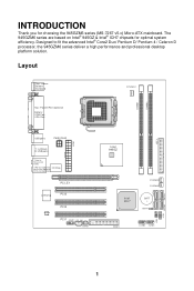
... (optional) I/O Chip M:CS-Out (optional) B:SS-Out (optional) PCI_E1 LAN Chip PCI3 AUDIO Chip PCI2 PCI1 JAUD1 CD_IN1 JSPD1 Intel 945GZ FDD1 SY S FAN 1 SY S FAN 2 BATT + JBAT1 JUSB2 JUSB1 SATA1 S ATA 4 JFP2 IDE 1 SATA3 JFP1 SATA2 1 INTRODUCTION Thank you for optimal system efficiency. Designed to fit the advanced Intel® Core2 Duo/ Pentium D/ Pentium 4 / Celeron D processor, the 945GZM6 series deliver a high performance and professional desktop...
... (optional) I/O Chip M:CS-Out (optional) B:SS-Out (optional) PCI_E1 LAN Chip PCI3 AUDIO Chip PCI2 PCI1 JAUD1 CD_IN1 JSPD1 Intel 945GZ FDD1 SY S FAN 1 SY S FAN 2 BATT + JBAT1 JUSB2 JUSB1 SATA1 S ATA 4 JFP2 IDE 1 SATA3 JFP1 SATA2 1 INTRODUCTION Thank you for optimal system efficiency. Designed to fit the advanced Intel® Core2 Duo/ Pentium D/ Pentium 4 / Celeron D processor, the 945GZM6 series deliver a high performance and professional desktop...

User Guide
Page 8
....msi.com.tw/testreport.htm) LAN l Supports 10/100 Mb/s Fast Ethernet by Realtek RTL 8100C l Or Supports 10/100/1000 Fast Ethermet by Realtek RTL 8110SC Audio l Chip integrated by Realtek ALC883, supports HD 5.1-channel audio-out l Or chip integrated by Realtek ALC888, supports HD 7.1-channel audio-out l Vista Premium compliance IDE l 1 IDE port l Supports Ultra DMA 66/100 mode l Supports PIO, Bus Master operation mode SATA l Four SATA ports by ICH7 chipset l Supports four SATA devices l Supports storage...
....msi.com.tw/testreport.htm) LAN l Supports 10/100 Mb/s Fast Ethernet by Realtek RTL 8100C l Or Supports 10/100/1000 Fast Ethermet by Realtek RTL 8110SC Audio l Chip integrated by Realtek ALC883, supports HD 5.1-channel audio-out l Or chip integrated by Realtek ALC888, supports HD 7.1-channel audio-out l Vista Premium compliance IDE l 1 IDE port l Supports Ultra DMA 66/100 mode l Supports PIO, Bus Master operation mode SATA l Four SATA ports by ICH7 chipset l Supports four SATA devices l Supports storage...
User Guide
Page 9
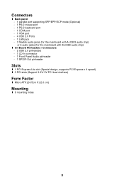
Connectors l Back panel - 1 parallel port supporting SPP/EPP/ECP mode (Optional) - 1 PS/2 mouse port - 1 PS/2 keyboard port - 1 COM port - 1 VGA port - 4 USB 2.0 Ports - 1 LAN jack - 3 flexible audio jacks (for the mainboard with ALC883 audio chip) or 6 audio jacks (for the mainboard with ALC888 audio chip) l On-Board Pinheaders / Connectors - 2 USB 2.0 pinheaders - 1 CD-In connector - 1 Front Panel Audio pinheader - 1 SPDIF-Out pinheader Slots l 1 PCI Express Lite slot (Special design, supports PCI Express x 4 speed) l 3 PCI slots (Support 3.3V/ 5V PCI bus interface) Form Factor l Micro-ATX (...
Connectors l Back panel - 1 parallel port supporting SPP/EPP/ECP mode (Optional) - 1 PS/2 mouse port - 1 PS/2 keyboard port - 1 COM port - 1 VGA port - 4 USB 2.0 Ports - 1 LAN jack - 3 flexible audio jacks (for the mainboard with ALC883 audio chip) or 6 audio jacks (for the mainboard with ALC888 audio chip) l On-Board Pinheaders / Connectors - 2 USB 2.0 pinheaders - 1 CD-In connector - 1 Front Panel Audio pinheader - 1 SPDIF-Out pinheader Slots l 1 PCI Express Lite slot (Special design, supports PCI Express x 4 speed) l 3 PCI slots (Support 3.3V/ 5V PCI bus interface) Form Factor l Micro-ATX (...
User Guide
Page 10
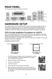
... some thermal paste on the top to prevent overheating. REAR PANEL The rear panel provides the following connectors: Mouse Parall el Port (optional) LAN Li ne-In RS-Out(optional) Li ne-Out CS-Out(optional) Key boa rd Serial Port VGA Port USB Ports Mic SS-Out(optional) HARDWARE SETUP This chapter tells you how to install the CPU, memory modules, and expansion cards, as well as the mouse, keyboard, etc.
... some thermal paste on the top to prevent overheating. REAR PANEL The rear panel provides the following connectors: Mouse Parall el Port (optional) LAN Li ne-In RS-Out(optional) Li ne-Out CS-Out(optional) Key boa rd Serial Port VGA Port USB Ports Mic SS-Out(optional) HARDWARE SETUP This chapter tells you how to install the CPU, memory modules, and expansion cards, as well as the mouse, keyboard, etc.
User Guide
Page 11
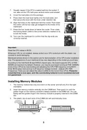
... CPU socket pin with pure vertical motion and reinstall. 8. Installing Memory Modules 1. Notch Vo l t 5 The appearance of the CPU/cooler installation only. Please be noted that the clip-ends are for the Core 2 Duo CPUs. Then push it ) to [Frequency/ Voltage Control]à[Adjust CPU FSB Frequency]. You can adjust the value to the Intel North Bridge 945GZ chipset spec, this section are correctly inserted. Turn...
... CPU socket pin with pure vertical motion and reinstall. 8. Installing Memory Modules 1. Notch Vo l t 5 The appearance of the CPU/cooler installation only. Please be noted that the clip-ends are for the Core 2 Duo CPUs. Then push it ) to [Frequency/ Voltage Control]à[Adjust CPU FSB Frequency]. You can adjust the value to the Intel North Bridge 945GZ chipset spec, this section are correctly inserted. Turn...
User Guide
Page 12
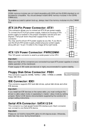
... the connectors are connected to proper ATX power supplies to one Serial ATA device. Power supply of 350 watts (and above) is highly recommended for jumper setting instructions. To connect the ATX 24-pin power supply, make sure the plug of the mainboard. IDE Connector: IDE1 This connector supports IDE hard disk drives, optical disk drives and other IDE devices. Otherwise, data loss may use the 20-pin ATX power supply, please plug your power supply along with DDR and the DDR2 standard is a high-speed Serial ATA interface port. To enable successful system boot-up...
... the connectors are connected to proper ATX power supplies to one Serial ATA device. Power supply of 350 watts (and above) is highly recommended for jumper setting instructions. To connect the ATX 24-pin power supply, make sure the plug of the mainboard. IDE Connector: IDE1 This connector supports IDE hard disk drives, optical disk drives and other IDE devices. Otherwise, data loss may use the 20-pin ATX power supply, please plug your power supply along with DDR and the DDR2 standard is a high-speed Serial ATA interface port. To enable successful system boot-up...
User Guide
Page 13
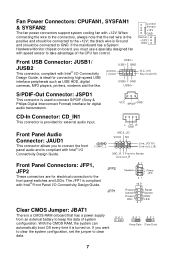
...; I /O Connectivity Design Guide. Control Sensor +12V GND Sensor +12V GND Front USB Connector: JUSB1/ JUSB2 This connector, compliant with +12V. VCC SPDIF GND CD-In Connector: CD_IN1 This connector is the positive and should be connected to clear data. 3 21 3 21 3 21 Keep Data Clear Data 7 JFP2 JFP1 87 Speaker Power LED 21 10 9 + -- + -+ Power Reset Switch Switch Power HDD LED LED 21 Clear CMOS Jumper: JBAT1 There is a CMOS RAM onboard that the red wire is provided for digital audio...
...; I /O Connectivity Design Guide. Control Sensor +12V GND Sensor +12V GND Front USB Connector: JUSB1/ JUSB2 This connector, compliant with +12V. VCC SPDIF GND CD-In Connector: CD_IN1 This connector is the positive and should be connected to clear data. 3 21 3 21 3 21 Keep Data Clear Data 7 JFP2 JFP1 87 Speaker Power LED 21 10 9 + -- + -+ Power Reset Switch Switch Power HDD LED LED 21 Clear CMOS Jumper: JBAT1 There is a CMOS RAM onboard that the red wire is provided for digital audio...
User Guide
Page 14
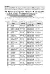
Then return to 1-2 pin position. PCI (Peripheral Component Interconnect) Express Slot The PCI Express slot supports the PCI Express interface expansion card. The PCI Express Lite slot is on; Supported PCI Express VGA Card List for PCI Express Lite Slot (PCI Express x4) MSI MSI MSI MSI ASUS MSI MSI MSI MSI MSI MSI MSI ASUS MSI MSI MSI Colorful ASUS MSI MSI MSI MSI MSI MSI MSI MSI MSI MSI MSI Model VGA Chip MS-8969 Geforce FX5700 MS-8968 Geforce FX5200 NX6600LE-TD128E/128B Geforce 6600LE NX6600LE-TD128E/128B Geforce 6600LE EN6600LE/SILENCER/TD Geforce 6600LE MS-V031 ...
Then return to 1-2 pin position. PCI (Peripheral Component Interconnect) Express Slot The PCI Express slot supports the PCI Express interface expansion card. The PCI Express Lite slot is on; Supported PCI Express VGA Card List for PCI Express Lite Slot (PCI Express x4) MSI MSI MSI MSI ASUS MSI MSI MSI MSI MSI MSI MSI ASUS MSI MSI MSI Colorful ASUS MSI MSI MSI MSI MSI MSI MSI MSI MSI MSI MSI Model VGA Chip MS-8969 Geforce FX5700 MS-8968 Geforce FX5200 NX6600LE-TD128E/128B Geforce 6600LE NX6600LE-TD128E/128B Geforce 6600LE EN6600LE/SILENCER/TD Geforce 6600LE MS-V031 ...
User Guide
Page 15
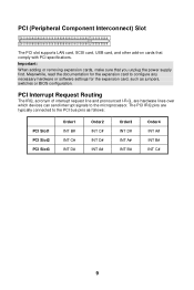
... pronounced I-R-Q, are typically connected to the PCI bus pins as jumpers, switches or BIOS configuration. PCI (Peripheral Component Interconnect) Slot The PCI slot supports LAN card, SCSI card, USB card, and other add-on cards that you unplug the power supply first. Important: When adding or removing expansion cards, make sure that comply with PCI specifications. The PCI IRQ pins are hardware lines over which devices can send interrupt signals to configure any necessary hardware or software settings for the expansion...
... pronounced I-R-Q, are typically connected to the PCI bus pins as jumpers, switches or BIOS configuration. PCI (Peripheral Component Interconnect) Slot The PCI slot supports LAN card, SCSI card, USB card, and other add-on cards that you unplug the power supply first. Important: When adding or removing expansion cards, make sure that comply with PCI specifications. The PCI IRQ pins are hardware lines over which devices can send interrupt signals to configure any necessary hardware or software settings for the expansion...
User Guide
Page 16
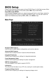
... settings for basic system configurations, such as time, date etc. Integrated Peripherals Use this menu for integrated peripherals. Advanced BIOS Features Use this menu to specify your settings for frequency/voltage control. 10 Frequency/Voltage Control Use this menu to setup the items of your system supports PnP/PCI. H/W Monitor This entry shows the status of special enhanced features. Power Management Setup Use this menu to specify your settings for power management. BIOS Setup Power on the screen, press key to enter Setup...
... settings for basic system configurations, such as time, date etc. Integrated Peripherals Use this menu for integrated peripherals. Advanced BIOS Features Use this menu to specify your settings for frequency/voltage control. 10 Frequency/Voltage Control Use this menu to setup the items of your system supports PnP/PCI. H/W Monitor This entry shows the status of special enhanced features. Power Management Setup Use this menu to specify your settings for power management. BIOS Setup Power on the screen, press key to enter Setup...
User Guide
Page 17
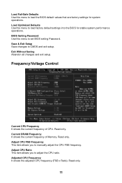
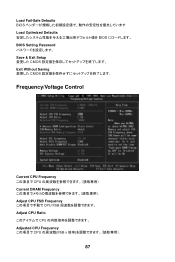
... Setup Save changes to adjust the CPU ratio. Current DRAM Frequency It shows the current frequency of CPU. Adjust CPU FSB Frequency This item allows you to CMOS and exit setup. Load Optimized Defaults Use this menu to manually adjust the CPU FSB frequency. Exit Without Saving Abandon all changes and exit setup. Adjusted CPU Frequency It shows the adjusted CPU frequency (FSB x Ratio). Frequency/Voltage Control Current CPU Frequency It shows the current frequency of Memory. BIOS Setting Password Use this menu to load the BIOS default values...
... Setup Save changes to adjust the CPU ratio. Current DRAM Frequency It shows the current frequency of CPU. Adjust CPU FSB Frequency This item allows you to CMOS and exit setup. Load Optimized Defaults Use this menu to manually adjust the CPU FSB frequency. Exit Without Saving Abandon all changes and exit setup. Adjusted CPU Frequency It shows the adjusted CPU frequency (FSB x Ratio). Frequency/Voltage Control Current CPU Frequency It shows the current frequency of Memory. BIOS Setting Password Use this menu to load the BIOS default values...
User Guide
Page 18
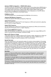
... remove (turn off) clocks from empty DIMM and PCI slots to adjust the Memory/PCI Express voltage. Any changes made to a higher frequency. But if you to select the PCI clock frequency (in clock speed which may just cause your overclocked processor to Enabled for EMI reduction. Remember to disable Spread Spectrum if you do not have any EMI problem, leave the setting at [Disabled] for optimal system stability and performance. Auto Disable DIMM/PCI Frequency When set...
... remove (turn off) clocks from empty DIMM and PCI slots to adjust the Memory/PCI Express voltage. Any changes made to a higher frequency. But if you to select the PCI clock frequency (in clock speed which may just cause your overclocked processor to Enabled for EMI reduction. Remember to disable Spread Spectrum if you do not have any EMI problem, leave the setting at [Disabled] for optimal system stability and performance. Auto Disable DIMM/PCI Frequency When set...
User Guide
Page 65
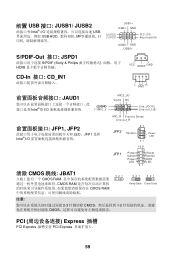
...(10) Line-out_L(9) MIC_R Front to Sense Line-out_R JFP1, JFP2 LED。JFP1 是和 Intel® I /O USB USB HDD MP3 USB1+ USB1- 前置 USB 接口: JUSB1/ JUSB2 Intel® I /O 87 JFP2 Speaker Power LED 21 10 9 + -- + -+ JFP1 Power Reset Switch Switch Power HDD LED LED 21 清除 CMOS 跳线: JBAT1 3 21 CMOS RAM CMOS RAM CMOS RAM 3 21 3 21 Keep Data Clear Data 注意: 2-3 CMOS 1-2 CMOS PCI Express 插槽 PCI Express PCI Express 59
...(10) Line-out_L(9) MIC_R Front to Sense Line-out_R JFP1, JFP2 LED。JFP1 是和 Intel® I /O USB USB HDD MP3 USB1+ USB1- 前置 USB 接口: JUSB1/ JUSB2 Intel® I /O 87 JFP2 Speaker Power LED 21 10 9 + -- + -+ JFP1 Power Reset Switch Switch Power HDD LED LED 21 清除 CMOS 跳线: JBAT1 3 21 CMOS RAM CMOS RAM CMOS RAM 3 21 3 21 Keep Data Clear Data 注意: 2-3 CMOS 1-2 CMOS PCI Express 插槽 PCI Express PCI Express 59
User Guide
Page 69
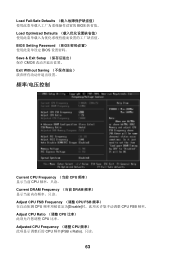
Load Fail-Safe Defaults BIOS Load Optimized Defaults BIOS Setting Password (BIOS BIOS Save & Exit Setup CMOS Exit Without Saving Current CPU Frequency (当前 CPU CPU Current DRAM Frequency (当前 DRAM Adjust CPU FSB Frequency (调整 CPU FSB CPU Disable CPU FSB 频率。 Adjust CPU Ratio (调整 CPU CPU 比率。 Adjusted CPU Frequency (调整 CPU CPU 频率(FSB x Ratio). 只读。 63
Load Fail-Safe Defaults BIOS Load Optimized Defaults BIOS Setting Password (BIOS BIOS Save & Exit Setup CMOS Exit Without Saving Current CPU Frequency (当前 CPU CPU Current DRAM Frequency (当前 DRAM Adjust CPU FSB Frequency (调整 CPU FSB CPU Disable CPU FSB 频率。 Adjust CPU Ratio (调整 CPU CPU 比率。 Adjusted CPU Frequency (调整 CPU CPU 频率(FSB x Ratio). 只读。 63
User Guide
Page 77
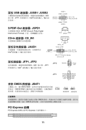
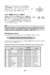
... Sense Line-out_R JFP1, JFP2 LED JFP1 Intel JFP2 87 Speaker Power LED 21 10 9 + -- + -+ JFP1 Power Reset Switch Switch Power HDD LED LED 21 清除 CMOS 跨接器: JBAT1 CMOS RAM CMOS RAM 3 21 3 21 3 21 K保ee留p D資at料a C清lea除r D資ata料 2-3 CMOS 1-2 CMOS PCI Express 插槽 PCI Express PCI Express 71 GND (2)VCC (1)VCC N.C.(10) Key,no pin(9) USB0- 面板 USB 連接器: JUSB1/ JUSB2...
... Sense Line-out_R JFP1, JFP2 LED JFP1 Intel JFP2 87 Speaker Power LED 21 10 9 + -- + -+ JFP1 Power Reset Switch Switch Power HDD LED LED 21 清除 CMOS 跨接器: JBAT1 CMOS RAM CMOS RAM 3 21 3 21 3 21 K保ee留p D資at料a C清lea除r D資ata料 2-3 CMOS 1-2 CMOS PCI Express 插槽 PCI Express PCI Express 71 GND (2)VCC (1)VCC N.C.(10) Key,no pin(9) USB0- 面板 USB 連接器: JUSB1/ JUSB2...
User Guide
Page 81
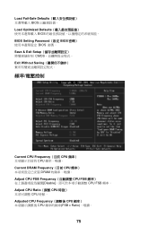
Load Fail-Safe Defaults BIOS Load Optimized Defaults BIOS BIOS Setting Password(設定 BIOS BIOS 密碼。 Save & Exit Setup CMOS Exit Without Saving Current CPU Frequency(目前 CPU CPU Current DRAM Frequency(目前 CPU DRAM Adjust CPU FSB Frequency CPU FSB Disable CPU FSB 頻率。 Adjust CPU Ratio(調整 CPU CPU 時脈。 Adjusted CPU Frequency CPU CPU FSB x Ratio 75
Load Fail-Safe Defaults BIOS Load Optimized Defaults BIOS BIOS Setting Password(設定 BIOS BIOS 密碼。 Save & Exit Setup CMOS Exit Without Saving Current CPU Frequency(目前 CPU CPU Current DRAM Frequency(目前 CPU DRAM Adjust CPU FSB Frequency CPU FSB Disable CPU FSB 頻率。 Adjust CPU Ratio(調整 CPU CPU 時脈。 Adjusted CPU Frequency CPU CPU FSB x Ratio 75
User Guide
Page 90
...12399; Intel® Front Panel I/O Connectivity Design Guide JFP1 10 9 + -- + -+ Power Reset Switch Switch Power HDD LED LED 21 クリア CMOS JBAT1 CMOS RAM BIOS 3 21 CMOS RAM OS CMOS ボタ 3 21 3 21 Keep Data Clear Data 注意: CMOS 2-3 1-2 CMOS PCI Express PCI Express PCI Express PCI Express Lite PCI Express x4 PCI-E x16 VGA x4 Supported PCI Express VGA Card List for PCI Express Lite Slot (PCI Express x4) MSI MSI MSI MSI ASUS MSI MSI MSI MSI MSI MSI MSI Model VGA Chip MS-8969 Geforce FX5700...
...12399; Intel® Front Panel I/O Connectivity Design Guide JFP1 10 9 + -- + -+ Power Reset Switch Switch Power HDD LED LED 21 クリア CMOS JBAT1 CMOS RAM BIOS 3 21 CMOS RAM OS CMOS ボタ 3 21 3 21 Keep Data Clear Data 注意: CMOS 2-3 1-2 CMOS PCI Express PCI Express PCI Express PCI Express Lite PCI Express x4 PCI-E x16 VGA x4 Supported PCI Express VGA Card List for PCI Express Lite Slot (PCI Express x4) MSI MSI MSI MSI ASUS MSI MSI MSI MSI MSI MSI MSI Model VGA Chip MS-8969 Geforce FX5700...
User Guide
Page 93
Load Fail-Safe Defaults BIOS Load Optimized Defaults BIOS BIOS Setting Password Save & Exit Setup CMOS Exit Without Saving CMOS Frequency/Voltage Control Current CPU Frequency CPU Current DRAM Frequency Adjust CPU FSB Frequency CPU FSB Adjust CPU Ratio CPU Adjusted CPU Frequency CPU FSB x 87
Load Fail-Safe Defaults BIOS Load Optimized Defaults BIOS BIOS Setting Password Save & Exit Setup CMOS Exit Without Saving CMOS Frequency/Voltage Control Current CPU Frequency CPU Current DRAM Frequency Adjust CPU FSB Frequency CPU FSB Adjust CPU Ratio CPU Adjusted CPU Frequency CPU FSB x 87


