

User Guide
Page 8
... Pentium 4/ Celeron D LGA 775 processors (For the latest information about CPU, please visit http:// www.msi.com.tw/cpusupport.htm) Supported FSB l 800 / 533 MHz Chipset l North Bridge: Intel® 945GZ chipset l South Bridge: Intel® ICH7 chipset Memory Support l DDR2 400/ 533 SDRAM (2GB Max) l 2 DDR2 DIMMs ...compatible components, please visit http:// www.msi.com.tw/testreport.htm) LAN l Supports 10/100 Mb/s Fast Ethernet by Realtek RTL 8100C l Or Supports 10/100/1000 Fast Ethermet by Realtek RTL 8110SC Audio l Chip integrated by Realtek ALC883, supports HD 5.1-channel audio-out l Or chip...
... Pentium 4/ Celeron D LGA 775 processors (For the latest information about CPU, please visit http:// www.msi.com.tw/cpusupport.htm) Supported FSB l 800 / 533 MHz Chipset l North Bridge: Intel® 945GZ chipset l South Bridge: Intel® ICH7 chipset Memory Support l DDR2 400/ 533 SDRAM (2GB Max) l 2 DDR2 DIMMs ...compatible components, please visit http:// www.msi.com.tw/testreport.htm) LAN l Supports 10/100 Mb/s Fast Ethernet by Realtek RTL 8100C l Or Supports 10/100/1000 Fast Ethermet by Realtek RTL 8110SC Audio l Chip integrated by Realtek ALC883, supports HD 5.1-channel audio-out l Or chip...
User Guide
Page 11
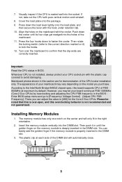
Mainboard photos shown in this board supports CPU of FSB 800MHz at FSB 1066MHz (Core 2 Duo CPUs) by default. There ...load plate, and then secure the lever with the plastic cap covered to [Frequency/ Voltage Control]à[Adjust CPU FSB Frequency]. The memory module has only one notch on the memory module is not recommended and not guaranteed.... Insert the memory module vertically into the socket. Turn over -spec, and this is not installed, always protect your CPU socket pin with the hook under retention tab. 10. Notch Vo l t 5 However, you may let your mainboard...
Mainboard photos shown in this board supports CPU of FSB 800MHz at FSB 1066MHz (Core 2 Duo CPUs) by default. There ...load plate, and then secure the lever with the plastic cap covered to [Frequency/ Voltage Control]à[Adjust CPU FSB Frequency]. The memory module has only one notch on the memory module is not recommended and not guaranteed.... Insert the memory module vertically into the socket. Turn over -spec, and this is not installed, always protect your CPU socket pin with the hook under retention tab. 10. Notch Vo l t 5 However, you may let your mainboard...
User Guide
Page 12
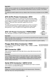
... supplies to ensure stable operation of 350 watts (and above) is highly recommended for jumper setting instructions. IDE Connector: IDE1 This connector supports IDE hard disk drives, optical disk drives and other IDE devices. You should always install DDR2 memory modules in the proper orientation and ...12V +12V +3.3V ATX 12V Power Connector: PWRCONN1 +12V +12V This 12V power connector is not backwards compatible. If you like to the CPU. Important: Please do not fold the Serial ATA cable into 90-degree angle. Otherwise, data loss may use the 20-pin ATX power ...
... supplies to ensure stable operation of 350 watts (and above) is highly recommended for jumper setting instructions. IDE Connector: IDE1 This connector supports IDE hard disk drives, optical disk drives and other IDE devices. You should always install DDR2 memory modules in the proper orientation and ...12V +12V +3.3V ATX 12V Power Connector: PWRCONN1 +12V +12V This 12V power connector is not backwards compatible. If you like to the CPU. Important: Please do not fold the Serial ATA cable into 90-degree angle. Otherwise, data loss may use the 20-pin ATX power ...
User Guide
Page 13
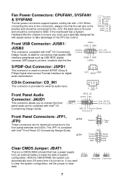
...Data 7 When connecting the wire to the connectors, always note that has a power supply from an external battery to keep the data of the CPU fan control. GND USB0+ S/PDIF-Out Connector: JSPD1 This connector is the positive and should be connected to the +12V; the black wire ... connect S/PDIF (Sony & Philips Digital Interconnect Format) interface for external audio input. Fan Power Connectors: CPUFAN1, SYSFAN1 & SYSFAN2 The fan power connectors support system cooling fan with speed sensor to take advantage of system configuration. If you must use a specially designed fan with +12V.
...Data 7 When connecting the wire to the connectors, always note that has a power supply from an external battery to keep the data of the CPU fan control. GND USB0+ S/PDIF-Out Connector: JSPD1 This connector is the positive and should be connected to the +12V; the black wire ... connect S/PDIF (Sony & Philips Digital Interconnect Format) interface for external audio input. Fan Power Connectors: CPUFAN1, SYSFAN1 & SYSFAN2 The fan power connectors support system cooling fan with speed sensor to take advantage of system configuration. If you must use a specially designed fan with +12V.
User Guide
Page 16
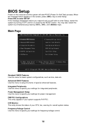
...the system by turning it OFF and On or pressing the RESET button. Integrated Peripherals Use this menu to setup the items of your system supports PnP/PCI. When the message below appears on the computer and the system will start POST (Power On Self Test) process. BIOS Setup Power... status. Main Page Standard CMOS Features Use this menu to specify your settings for integrated peripherals. PNP/PCI Configurations This entry appears if your CPU, fan, warning for frequency/voltage control. 10 Press DEL to enter SETUP If the message disappears before you respond and you still wish to...
...the system by turning it OFF and On or pressing the RESET button. Integrated Peripherals Use this menu to setup the items of your system supports PnP/PCI. When the message below appears on the computer and the system will start POST (Power On Self Test) process. BIOS Setup Power... status. Main Page Standard CMOS Features Use this menu to specify your settings for integrated peripherals. PNP/PCI Configurations This entry appears if your CPU, fan, warning for frequency/voltage control. 10 Press DEL to enter SETUP If the message disappears before you respond and you still wish to...


