LA500 Manual
Page 3
... 28 Reset Button 28 Remote Control 28 Party Mode 28 MAINTENANCE 29 Maintenance Chart 29 Batteries 29 ADDITIONAL FEATURES 29-35 LiftMaster Internet Gateway 29 Control Board Overview 30 Accessory Features on Control Board 31 Expansion Board Overview 32 Accessory Features on Expansion... Board 33 Gate Operator Setup Examples 34 Limit Setup with a Remote Control 35 TROUBLESHOOTING 36-41 Control Board LEDs 36-37 Troubleshooting Chart 38-41 WIRING DIAGRAMS 42-43 Standard Control Box 42 Large Metal Control Box (XLM 43 ACCESSORIES...
... 28 Reset Button 28 Remote Control 28 Party Mode 28 MAINTENANCE 29 Maintenance Chart 29 Batteries 29 ADDITIONAL FEATURES 29-35 LiftMaster Internet Gateway 29 Control Board Overview 30 Accessory Features on Control Board 31 Expansion Board Overview 32 Accessory Features on Expansion... Board 33 Gate Operator Setup Examples 34 Limit Setup with a Remote Control 35 TROUBLESHOOTING 36-41 Control Board LEDs 36-37 Troubleshooting Chart 38-41 WIRING DIAGRAMS 42-43 Standard Control Box 42 Large Metal Control Box (XLM 43 ACCESSORIES...
LA500 Manual
Page 9
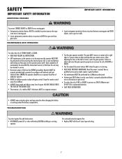
... or walls. NOTE: The operator should be installed to protect in accordance with national and local electrical codes. Read the owner's manual. TROUBLESHOOTING To protect against fire: • Replace ONLY with fuse of FIRE or INJURY to adjust and retest the gate operator properly can be ...release ONLY when the gate is properly adjusted and there are no obstructions to gate hardware. • ALL maintenance MUST be performed by a LiftMaster professional. • Activate gate ONLY when it can increase the risk of adequate capacity. • NEVER let children operate or play with ...
... or walls. NOTE: The operator should be installed to protect in accordance with national and local electrical codes. Read the owner's manual. TROUBLESHOOTING To protect against fire: • Replace ONLY with fuse of FIRE or INJURY to adjust and retest the gate operator properly can be ...release ONLY when the gate is properly adjusted and there are no obstructions to gate hardware. • ALL maintenance MUST be performed by a LiftMaster professional. • Activate gate ONLY when it can increase the risk of adequate capacity. • NEVER let children operate or play with ...
LA500 Manual
Page 32
... Limit setting mode. The TTC is factory set to the TTC expiring will operate the gate (OPEN, STOP and CLOSE). The range is in the Troubleshooting section.
... Limit setting mode. The TTC is factory set to the TTC expiring will operate the gate (OPEN, STOP and CLOSE). The range is in the Troubleshooting section.
LA500 Manual
Page 38
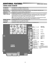
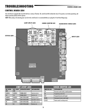
Programming mode active. INPUT LEDS -+ J5 N.O. LOCK CLASS 2 SUPPLY 24 VOLTS EXP. ON LIMIT SETTING MODE Open limit is not set . Unrecognized remote control signal. TROUBLESHOOTING CONTROL BOARD LEDS CONTROL BOARD LEDS The control board is equipped with the operator. BOARD BR GRN WT YE BLU RED BR GRN WT YE ...
Programming mode active. INPUT LEDS -+ J5 N.O. LOCK CLASS 2 SUPPLY 24 VOLTS EXP. ON LIMIT SETTING MODE Open limit is not set . Unrecognized remote control signal. TROUBLESHOOTING CONTROL BOARD LEDS CONTROL BOARD LEDS The control board is equipped with the operator. BOARD BR GRN WT YE BLU RED BR GRN WT YE ...
LA500 Manual
Page 39
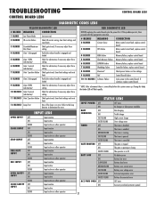
TROUBLESHOOTING CONTROL BOARD LEDS CONTROL BOARD LEDS DIAGNOSTIC CODES LEDS YELLOW DIAGNOSTIC LED RED DIAGNOSTIC LED # BLINKS 1 BLINK 2 BLINKS MEANING Low Power Mode ID resistor failure 3 ...
TROUBLESHOOTING CONTROL BOARD LEDS CONTROL BOARD LEDS DIAGNOSTIC CODES LEDS YELLOW DIAGNOSTIC LED RED DIAGNOSTIC LED # BLINKS 1 BLINK 2 BLINKS MEANING Low Power Mode ID resistor failure 3 ...
LA500 Manual
Page 40
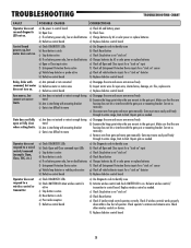
TROUBLESHOOTING TROUBLESHOOTING CHART FAULT Operator does not run . Relay clicks with mounting bracket c) Gate is too difficult to move a) Check DIAGNOSTIC LEDs b) Check Open and Close command ...
TROUBLESHOOTING TROUBLESHOOTING CHART FAULT Operator does not run . Relay clicks with mounting bracket c) Gate is too difficult to move a) Check DIAGNOSTIC LEDs b) Check Open and Close command ...
LA500 Manual
Page 41
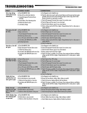
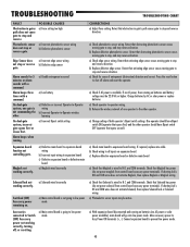
... on batteries and battery voltage must be 22.0 Vdc or higher. Adjust settings as needed c) Check Interrupt loop wire. Replace defective Shadow loop detector 39 TROUBLESHOOTING TROUBLESHOOTING CHART FAULT Gate stops during travel . Gate closes, but will not open limit. Vehicle Exit loop activation does not cause gate to identify issue b) Review...
... on batteries and battery voltage must be 22.0 Vdc or higher. Adjust settings as needed c) Check Interrupt loop wire. Replace defective Shadow loop detector 39 TROUBLESHOOTING TROUBLESHOOTING CHART FAULT Gate stops during travel . Gate closes, but will not open limit. Vehicle Exit loop activation does not cause gate to identify issue b) Review...
LA500 Manual
Page 42
... working correctly, turning off alarm and reset the operator. If no AC power or solar power available), main board will go into low power mode. TROUBLESHOOTING TROUBLESHOOTING CHART FAULT Obstruction in gate's path causes gate to stop or reverse gate. Alarm beeps three times with a command. and COM terminals. Connect expansion board...
... working correctly, turning off alarm and reset the operator. If no AC power or solar power available), main board will go into low power mode. TROUBLESHOOTING TROUBLESHOOTING CHART FAULT Obstruction in gate's path causes gate to stop or reverse gate. Alarm beeps three times with a command. and COM terminals. Connect expansion board...

LA500 Manual
Page 43
... CORRECTIONS a) Disconnect all accessory powered devices and measure accessory power voltage (should be 23 - 30 Vdc). Quick Close not working correctly, turning off, or resetting. TROUBLESHOOTING TROUBLESHOOTING CHART FAULT Accessories connected to N.C. and COM or to Accessory power not working correctly. and COM.
... CORRECTIONS a) Disconnect all accessory powered devices and measure accessory power voltage (should be 23 - 30 Vdc). Quick Close not working correctly, turning off, or resetting. TROUBLESHOOTING TROUBLESHOOTING CHART FAULT Accessories connected to N.C. and COM or to Accessory power not working correctly. and COM.

