
Solar Gate Access System Daily Cycle Chart Manual
Page 1
... 3 4 Not Available 1 1 2 1 NUMBER OF CYCLES PER DAY (SOLAR-SINGLE SWING GATE) Swing Gate ACCESSORY ZONE 1 Installation POWER (6 Hrs (12 ft. 800 lb. LA500 Solar Gate Access System Daily Cycle Chart The LA500 Solar Gate Access System utilizes an Solar panel(s) must be two 20W (12V) panels in series. 100 174 69... 25 200 76 0 300 270 185 60W SOLAR PANEL 50 300 215 134 NOTE: 100...
... 3 4 Not Available 1 1 2 1 NUMBER OF CYCLES PER DAY (SOLAR-SINGLE SWING GATE) Swing Gate ACCESSORY ZONE 1 Installation POWER (6 Hrs (12 ft. 800 lb. LA500 Solar Gate Access System Daily Cycle Chart The LA500 Solar Gate Access System utilizes an Solar panel(s) must be two 20W (12V) panels in series. 100 174 69... 25 200 76 0 300 270 185 60W SOLAR PANEL 50 300 215 134 NOTE: 100...
"Manufacturer's Certification for Credit" Manual
Page 1
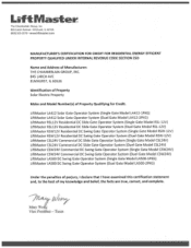
...LiftMaster LA412 Solar Gate Operator System (Single Gate Model LA412-1PKG) LiftMaster LA412 Solar Gate Operator System (Duel Gate Model LA412-2PKG) LiftMaster RSL12V Residential DC Slide Gate Operator System (Single Gate Model RSL-12V) LiftMaster RSL12V Residential DC Slide Gate Operator System (Duel Gate Model RSL-12V) LiftMaster... Gate Model CSW24V) LiftMaster CSW24V Commercial DC Swing Gate Operator System (Duel Gate Model CSW24V) LiftMaster LA500 DC Swing Gate Operator System (Single Gate Model LA500-1PKG) LiftMaster LA500 DC Swing Gate Operator System (Duel Gate Model LA500-2PKG) Under the ...
...LiftMaster LA412 Solar Gate Operator System (Single Gate Model LA412-1PKG) LiftMaster LA412 Solar Gate Operator System (Duel Gate Model LA412-2PKG) LiftMaster RSL12V Residential DC Slide Gate Operator System (Single Gate Model RSL-12V) LiftMaster RSL12V Residential DC Slide Gate Operator System (Duel Gate Model RSL-12V) LiftMaster... Gate Model CSW24V) LiftMaster CSW24V Commercial DC Swing Gate Operator System (Duel Gate Model CSW24V) LiftMaster LA500 DC Swing Gate Operator System (Single Gate Model LA500-1PKG) LiftMaster LA500 DC Swing Gate Operator System (Duel Gate Model LA500-2PKG) Under the ...

LA500 Manual
Page 8
...) is on, heater may be hot. • To AVOID damaging gas, power or other control may be performed until disconnecting the electrical power (AC or solar and battery) and locking-out the power via the operator power switch. We recommend that time the unit may also need adjustment. • After ANY...
...) is on, heater may be hot. • To AVOID damaging gas, power or other control may be performed until disconnecting the electrical power (AC or solar and battery) and locking-out the power via the operator power switch. We recommend that time the unit may also need adjustment. • After ANY...
LA500 Manual
Page 9
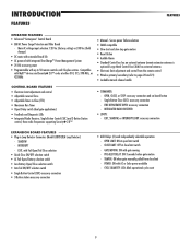
... is not moving. • KEEP GATES PROPERLY MAINTAINED. Pedestrians MUST use ONLY LiftMaster part 29-NP712 for vehicles ONLY. For continued protection against fire and electrocution: • DISCONNECT power (AC or solar and battery) BEFORE installing or servicing operator. Upon completion of adequate capacity. &#...the gate operator monthly. To reduce the risk of FIRE or INJURY to gate hardware. • ALL maintenance MUST be performed by a LiftMaster professional. • Activate gate ONLY when it can increase the risk of same type and rating. 7 Read the owner's manual. Keep ...
... is not moving. • KEEP GATES PROPERLY MAINTAINED. Pedestrians MUST use ONLY LiftMaster part 29-NP712 for vehicles ONLY. For continued protection against fire and electrocution: • DISCONNECT power (AC or solar and battery) BEFORE installing or servicing operator. Upon completion of adequate capacity. &#...the gate operator monthly. To reduce the risk of FIRE or INJURY to gate hardware. • ALL maintenance MUST be performed by a LiftMaster professional. • Activate gate ONLY when it can increase the risk of same type and rating. 7 Read the owner's manual. Keep ...
LA500 Manual
Page 10
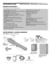
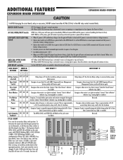
....35" (102.5 cm) Post Bracket Gate Bracket Warning Signs (2) and Warranty Card OR Key (2) Terminal Block Connector MODEL LA500-S ONLY Standard Control Box with Toroid Kit ONLY) Solar Power Max: 24 Vdc at 50 watts max. Main Supply (Motor): 24 Vdc Accessory Power: 24 Vdc nominal Class II battery voltage source is...: -40°C to 60°C (-40°F to 1000 feet - 100 mA NOTE: Increased accessory power drawn from the operator will shorten the battery life (solar applications ONLY).
....35" (102.5 cm) Post Bracket Gate Bracket Warning Signs (2) and Warranty Card OR Key (2) Terminal Block Connector MODEL LA500-S ONLY Standard Control Box with Toroid Kit ONLY) Solar Power Max: 24 Vdc at 50 watts max. Main Supply (Motor): 24 Vdc Accessory Power: 24 Vdc nominal Class II battery voltage source is...: -40°C to 60°C (-40°F to 1000 feet - 100 mA NOTE: Increased accessory power drawn from the operator will shorten the battery life (solar applications ONLY).
LA500 Manual
Page 11
... connection • AUX Relays (2) each independently selectable operation: - SHADOW - EXIT, with gate moving - PRE-ALERT DELAY: ON 3 seconds before gate motion - Compatible with AC or Solar power available - CLOSE LIMIT: OFF at open limit switch - Single Button Close (SBC): accessory connection - OPEN, CLOSE, or STOP: accessory connection and on-board button...
... connection • AUX Relays (2) each independently selectable operation: - SHADOW - EXIT, with gate moving - PRE-ALERT DELAY: ON 3 seconds before gate motion - Compatible with AC or Solar power available - CLOSE LIMIT: OFF at open limit switch - Single Button Close (SBC): accessory connection - OPEN, CLOSE, or STOP: accessory connection and on-board button...
LA500 Manual
Page 20
... "FIRE EPT " OPEN XIT SHADOW CLOSE EYES/ NTERRUPT +- -+ J5 N C. J15 + BATT - + DC POWER BR GRN WT YE BLU RED BR GRN WT YE BLU RED SOLAR / CHARGER + LOCK LA S 2 U P Y 4V L S GROUND ID RESET ALARM ACCESSORY POWER + ON- + SW-. EXP. If you should cut the ground wire too short, break it, or...
... "FIRE EPT " OPEN XIT SHADOW CLOSE EYES/ NTERRUPT +- -+ J5 N C. J15 + BATT - + DC POWER BR GRN WT YE BLU RED BR GRN WT YE BLU RED SOLAR / CHARGER + LOCK LA S 2 U P Y 4V L S GROUND ID RESET ALARM ACCESSORY POWER + ON- + SW-. EXP. If you should cut the ground wire too short, break it, or...
LA500 Manual
Page 24
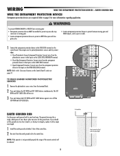
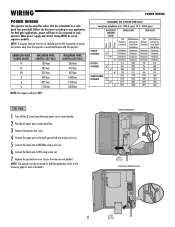
.../ 19 ft. 500 lb. Ensure the wires are not pinched. Main power supply and control wiring MUST be wired for either 120 Vac (standard) or a solar panel (not provided). Refer to the Accessory page for 240 Vac application. WIRING POWER WIRING This operator can also be connected to each operator. For...
.../ 19 ft. 500 lb. Ensure the wires are not pinched. Main power supply and control wiring MUST be wired for either 120 Vac (standard) or a solar panel (not provided). Refer to the Accessory page for 240 Vac application. WIRING POWER WIRING This operator can also be connected to each operator. For...
LA500 Manual
Page 25
...where temperatures reach below 32˚F. WIRING POWER WIRING CONTINUED... For solar applications, a minimum of two 10W solar panels in an open area clear of obstructions and shading for solar applications. We recommend LiftMaster low power draw accessories to minimize power draw, refer to the ...J15 plug labeled BATT(-)(+) DC(-)(+) on a regular basis for Large Metal Control Box (XLM) ONLY). NOTE: Solar power maximum is not supported ...
...where temperatures reach below 32˚F. WIRING POWER WIRING CONTINUED... For solar applications, a minimum of two 10W solar panels in an open area clear of obstructions and shading for solar applications. We recommend LiftMaster low power draw accessories to minimize power draw, refer to the ...J15 plug labeled BATT(-)(+) DC(-)(+) on a regular basis for Large Metal Control Box (XLM) ONLY). NOTE: Solar power maximum is not supported ...
LA500 Manual
Page 26
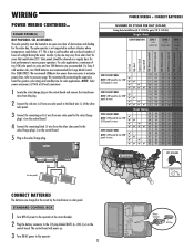
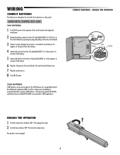
WIRING CONNECT BATTERIES The batteries are required for a Large Metal Control Box (XLM) solar application ONLY. A wall or column mount installation is now engaged. 24 CONNECT BATTERIES + ENGAGE THE OPERATOR Battery Connector J15 Plug Red Wire Jumper Black Wire .... 5 Connect the black wire from the J15 plug labeled BATT (-) to the J15 plug labeled BATT(-)(+) DC(-)(+) on the control board by the transformer or solar panel. The operator is recommended when using the 33AH batteries. A battery tray (model K10-36183) and battery harness (model K94-36596) are charged in place...
WIRING CONNECT BATTERIES The batteries are required for a Large Metal Control Box (XLM) solar application ONLY. A wall or column mount installation is now engaged. 24 CONNECT BATTERIES + ENGAGE THE OPERATOR Battery Connector J15 Plug Red Wire Jumper Black Wire .... 5 Connect the black wire from the J15 plug labeled BATT (-) to the J15 plug labeled BATT(-)(+) DC(-)(+) on the control board by the transformer or solar panel. The operator is recommended when using the 33AH batteries. A battery tray (model K10-36183) and battery harness (model K94-36596) are charged in place...
LA500 Manual
Page 31
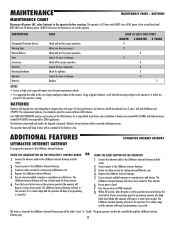
...wear or damage Check all for proper operation Inspect all power (AC, solar, battery) to the operator if it enters learn mode). The LiftMaster Internet Gateway will pair to the operator before servicing. The LiftMaster Internet Gateway will stay in learn mode for three minutes. 6 Press the... Check and test for proper operation Make sure they are required for a Large Metal Control Box solar installation. For best performance, the batteries should be controlled through the LiftMaster Internet Gateway app. 29 Within 30 seconds, when the gate is at the site voltage readings ...
...wear or damage Check all for proper operation Inspect all power (AC, solar, battery) to the operator if it enters learn mode). The LiftMaster Internet Gateway will pair to the operator before servicing. The LiftMaster Internet Gateway will stay in learn mode for three minutes. 6 Press the... Check and test for proper operation Make sure they are required for a Large Metal Control Box solar installation. For best performance, the batteries should be controlled through the LiftMaster Internet Gateway app. 29 Within 30 seconds, when the gate is at the site voltage readings ...
LA500 Manual
Page 32
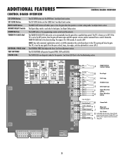
... dial adjusts the force. The TTC is used only for dual gates. BOARD BR GRN WT YE BLU RED BR GRN WT YE BLU RED SOLAR / CHARGER + GROUND ID RESET ALARM 30 ADDITIONAL FEATURES CONTROL BOARD OVERVIEW CONTROL BOARD OVERVIEW SET OPEN Button SET CLOSE Button MOVE GATE Button BIPART DELAY...
... dial adjusts the force. The TTC is used only for dual gates. BOARD BR GRN WT YE BLU RED BR GRN WT YE BLU RED SOLAR / CHARGER + GROUND ID RESET ALARM 30 ADDITIONAL FEATURES CONTROL BOARD OVERVIEW CONTROL BOARD OVERVIEW SET OPEN Button SET CLOSE Button MOVE GATE Button BIPART DELAY...
LA500 Manual
Page 34
... = 22 V • When set to stop and reverse. Relay always off . light). warning light or sounder). Power ON ON OFF Energizes when AC power or solar power is between 1,000 and 9,999,000 cycles. Tamper ON OFF ON Energizes if gate is faulted and inoperative). If under 1,000 cycles the Open...
... = 22 V • When set to stop and reverse. Relay always off . light). warning light or sounder). Power ON ON OFF Energizes when AC power or solar power is between 1,000 and 9,999,000 cycles. Tamper ON OFF ON Energizes if gate is faulted and inoperative). If under 1,000 cycles the Open...
LA500 Manual
Page 38
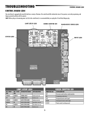
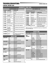
...that have a variety of the operator, assist with programming, and diagnose potential problems with many LEDs that you unplug the J15 and Solar/Charger plug. Recognized remote control signal. TROUBLESHOOTING CONTROL BOARD LEDS CONTROL BOARD LEDS The control board is equipped with the operator. INPUT ...+ BATT J15 + DC POWER ACCESSORY POWER + ON- + SW-. BOARD BR GRN WT YE BLU RED BR GRN WT YE BLU RED SOLAR / CHARGER + GROUND ID RESET ALARM SET OPEN LED BLINKING OFF BLINKING BLINKING ON ON LIMIT SETUP LEDS SET CLOSE OPERATOR MODE EXPLANATION LED BLINKING...
...that have a variety of the operator, assist with programming, and diagnose potential problems with many LEDs that you unplug the J15 and Solar/Charger plug. Recognized remote control signal. TROUBLESHOOTING CONTROL BOARD LEDS CONTROL BOARD LEDS The control board is equipped with the operator. INPUT ...+ BATT J15 + DC POWER ACCESSORY POWER + ON- + SW-. BOARD BR GRN WT YE BLU RED BR GRN WT YE BLU RED SOLAR / CHARGER + GROUND ID RESET ALARM SET OPEN LED BLINKING OFF BLINKING BLINKING ON ON LIMIT SETUP LEDS SET CLOSE OPERATOR MODE EXPLANATION LED BLINKING...
LA500 Manual
Page 39
... Input active BLINK Input active on other operator OFF Input inactive ON Input active STATUS LEDS INPUT POWER OFF OFF state ON AC charger or Solar power available BATT OFF CHARGING ON Not charging Trickle charge FAST BLINK High current charge FASTER BLINK Over voltage error TIMER OFF The timer is...
... Input active BLINK Input active on other operator OFF Input inactive ON Input active STATUS LEDS INPUT POWER OFF OFF state ON AC charger or Solar power available BATT OFF CHARGING ON Not charging Trickle charge FAST BLINK High current charge FASTER BLINK Over voltage error TIMER OFF The timer is...
LA500 Manual
Page 40
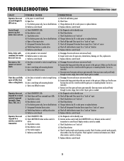
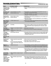
...button is stuck e) Poor radio reception f) Defective control board CORRECTIONS a) Check AC and battery power b) Check fuses c) Charge batteries by AC or solar power or replace batteries f) Check all Entrapment Protection Device inputs for a "stuck on" sensor g) Check all Open and Close inputs for a "... inputs for a "stuck on" input c) Check Stop button is not "stuck on" d) Check Reset button e) Charges batteries by AC or solar power or replace batteries d) Replace defective control board a) Use Diagnostic code to identify issue b) Activate wireless control and check XMITTER LED is on ...
...button is stuck e) Poor radio reception f) Defective control board CORRECTIONS a) Check AC and battery power b) Check fuses c) Charge batteries by AC or solar power or replace batteries f) Check all Entrapment Protection Device inputs for a "stuck on" sensor g) Check all Open and Close inputs for a "... inputs for a "stuck on" input c) Check Stop button is not "stuck on" d) Check Reset button e) Charges batteries by AC or solar power or replace batteries d) Replace defective control board a) Use Diagnostic code to identify issue b) Activate wireless control and check XMITTER LED is on ...
LA500 Manual
Page 41
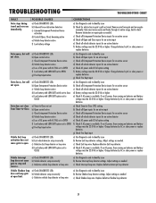
...detector setup incorrectly c) Defective vehicle loop detector or loop wire CORRECTIONS a) Use Diagnostic code to stop and reverse. Charge batteries by AC or solar power or replace batteries a) Use Diagnostic code to identify issue b) Check all Entrapment Protection Device inputs for an active sensor c) Check all... vehicle detector inputs for an active detector d) Battery voltage must be 22.0 Vdc or higher. Charge batteries by AC or solar power or replace batteries g) Check Fire Dept input a) Use Diagnostic code to identify issue b) Check all Open inputs for an active input ...
...detector setup incorrectly c) Defective vehicle loop detector or loop wire CORRECTIONS a) Use Diagnostic code to stop and reverse. Charge batteries by AC or solar power or replace batteries a) Use Diagnostic code to identify issue b) Check all Entrapment Protection Device inputs for an active sensor c) Check all... vehicle detector inputs for an active detector d) Battery voltage must be 22.0 Vdc or higher. Charge batteries by AC or solar power or replace batteries g) Check Fire Dept input a) Use Diagnostic code to identify issue b) Check all Open inputs for an active input ...
LA500 Manual
Page 42
...board disconnected and running on . Switched (SW) Accessory power remaining on batteries (no AC power, then running . If no AC power or solar power available), main board will go into low power mode. If required, replace wire cable. b) Check wiring to all inputs on batteries and ... or Solenoid wiring a) Photoelectric sensor inputs may be 22.0 Vdc or higher. Accessories connected to -operator wiring. Charge batteries by AC or solar power or replace batteries a) Check operator-to Switch (SW) Accessory power not working correctly, turning off alarm and reset the operator. POSSIBLE ...
...board disconnected and running on . Switched (SW) Accessory power remaining on batteries (no AC power, then running . If no AC power or solar power available), main board will go into low power mode. If required, replace wire cable. b) Check wiring to all inputs on batteries and ... or Solenoid wiring a) Photoelectric sensor inputs may be 22.0 Vdc or higher. Accessories connected to -operator wiring. Charge batteries by AC or solar power or replace batteries a) Check operator-to Switch (SW) Accessory power not working correctly, turning off alarm and reset the operator. POSSIBLE ...
LA500 Manual
Page 44
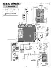
... Power Connection L GND N Tranformer Run Kit (Optional) Switch/5A Breaker L Connect Outlets to Outlet Metal Chassis With a Single Screw Primary Operator Secondary Operator Two 12V Solar Panels in Series + - + - Input Power Connection N GND EMI FILTER/SURGE PROTECTION BOARD Gray Yellow Blue White Brown Purple Red Orange Transformer 200 VA STANDARD CONTROL... Photoelectric Sensors Photoelectric Sensors Field Wiring Edge J5 N O COM N C J15 + BATT - + DC POWER BR GRN WT YE BLU RED BR GRN WT YE BLU RED SOLAR / CHARGER + -
... Power Connection L GND N Tranformer Run Kit (Optional) Switch/5A Breaker L Connect Outlets to Outlet Metal Chassis With a Single Screw Primary Operator Secondary Operator Two 12V Solar Panels in Series + - + - Input Power Connection N GND EMI FILTER/SURGE PROTECTION BOARD Gray Yellow Blue White Brown Purple Red Orange Transformer 200 VA STANDARD CONTROL... Photoelectric Sensors Photoelectric Sensors Field Wiring Edge J5 N O COM N C J15 + BATT - + DC POWER BR GRN WT YE BLU RED BR GRN WT YE BLU RED SOLAR / CHARGER + -
LA500 Manual
Page 45
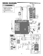
... + + (-) (+) (+) (-) Photoelectric Sensors Photoelectric Sensors J5 N O COM N C J15 + BATT - + DC POWER BR GRN WT YE BLU RED BR GRN WT YE BLU RED SOLAR / CHARGER + - Secondary Operator Two 12V Solar Panels in Series + - + - LARGE METAL CONTROL BOX (XLM) Field Wiring Reset Switch Wire Loop Wire Loop Wire Loop Field Wiring WIRING DIAGRAMS To...
... + + (-) (+) (+) (-) Photoelectric Sensors Photoelectric Sensors J5 N O COM N C J15 + BATT - + DC POWER BR GRN WT YE BLU RED BR GRN WT YE BLU RED SOLAR / CHARGER + - Secondary Operator Two 12V Solar Panels in Series + - + - LARGE METAL CONTROL BOX (XLM) Field Wiring Reset Switch Wire Loop Wire Loop Wire Loop Field Wiring WIRING DIAGRAMS To...


