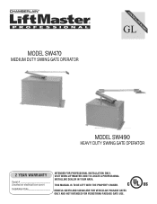
LiftMaster SW470 Support Question
LiftMaster SW470 Support Question
Find answers below for this question about LiftMaster SW470.Need a LiftMaster SW470 manual? We have 2 online manuals for this item!
Question posted by All4scott on November 1st, 2023
Where Is The Battery Located In My Sw470? My Gate Is Electric And Not Solar Powe
Current Answers
Answer #1: Posted by SonuKumar on November 1st, 2023 9:08 PM

Member since:
May 9th, 2021 Points: 16,604,800

Here are the steps on how to locate the battery in your SW470 gate operator:
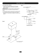
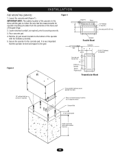
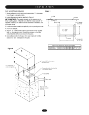
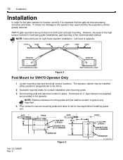
Locate the control box for your gate operator. This is typically a metal box mounted on a post near the gate.
Open the control box by removing the screws that secure the cover.
Inside the control box, you will see the battery. It is typically a large, black battery with two terminals.
To remove the battery, disconnect the two terminals from the battery.
Be careful when handling the battery, as it can be heavy and may contain acid.
Once you have removed the battery, you can replace it with a new one. Be sure to purchase a battery that is the same type and size as the original battery.
Here are some additional tips for replacing the battery in your SW470 gate operator:
Make sure that the gate is in the closed position before you start replacing the battery.
Disconnect the power supply to the gate operator before you start replacing the battery.
Be careful when handling the battery, as it can be heavy and may contain acid.
Dispose of the old battery properly.
If you have any difficulty replacing the battery, please contact your gate operator manufacturer for assistance.
Please respond to my effort to provide you with the best possible solution by using the "Acceptable Solution" and/or the "Helpful" buttons when the answer has proven to be helpful.
Regards,
Sonu
Your search handyman for all e-support needs!!
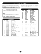
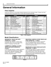
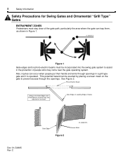
Related LiftMaster SW470 Manual Pages
Similar Questions

Gate won't open from 2pm to 4pm everyday, motor just clicks when pressing button

the measurements at the base for mounting is 20.25 inches. My gate is 13 feet 8 inches wide. Will th...

