SW490 GL BOARD Manual
Page 2
... Arm and Gate Bracket Installation (SW470 12 Control Arm Assembly (SW490 13-14 Manual Disconnect 14 WIRING AVERTISSEMENT Power Wiring Installation 15 On/Off Switch Power Wiring 16 Stop/Reset Button Control Wiring 16 ADJAUSTTMTEENTNTION Programming the Radio Receiver 17 Limit Switch Adjustment 18 RPM Sensor (Hall Effect) Adjustment 19 SAMS (Sequenced Access Management System 20 Accessory Wiring 21-22 Control Board Illustration 23 Controller Programming and Features 24-25 Program Settings 26-27 TROUBLESHOOTING 28-29 MAINTENANCE Operator Maintenance 30 Single Phase Wiring Diagram...
... Arm and Gate Bracket Installation (SW470 12 Control Arm Assembly (SW490 13-14 Manual Disconnect 14 WIRING AVERTISSEMENT Power Wiring Installation 15 On/Off Switch Power Wiring 16 Stop/Reset Button Control Wiring 16 ADJAUSTTMTEENTNTION Programming the Radio Receiver 17 Limit Switch Adjustment 18 RPM Sensor (Hall Effect) Adjustment 19 SAMS (Sequenced Access Management System 20 Accessory Wiring 21-22 Control Board Illustration 23 Controller Programming and Features 24-25 Program Settings 26-27 TROUBLESHOOTING 28-29 MAINTENANCE Operator Maintenance 30 Single Phase Wiring Diagram...
SW490 GL BOARD Manual
Page 5
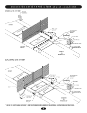
... DEVICE LOCATIONS SWING GATE SYSTEM Telephone Entry System STREET Interrupt (Safety) Loop Photo eye for close cycle DUAL SWING GATE SYSTEM Photo eye for open cycle Shadow Loop Interrupt (Safety) Loop 4' (1.2 m) Typical COMPLEX OR PARKING LOT Run twisted wire* from loop to operator Seal Loops* 1-1/2" (37 mm) Loop Wire* Layer 1/4" (6 mm) or larger depending on loop wire size STREET InLteororuppt (Safety) Photo eye for open cycle Gate 2 Run twisted wire* from loop to operator Seal Loops* Gate 1 Photo eye for open cycle Photo eye for close cycle Shadow Loop InLteororuppt (Safety...
... DEVICE LOCATIONS SWING GATE SYSTEM Telephone Entry System STREET Interrupt (Safety) Loop Photo eye for close cycle DUAL SWING GATE SYSTEM Photo eye for open cycle Shadow Loop Interrupt (Safety) Loop 4' (1.2 m) Typical COMPLEX OR PARKING LOT Run twisted wire* from loop to operator Seal Loops* 1-1/2" (37 mm) Loop Wire* Layer 1/4" (6 mm) or larger depending on loop wire size STREET InLteororuppt (Safety) Photo eye for open cycle Gate 2 Run twisted wire* from loop to operator Seal Loops* Gate 1 Photo eye for open cycle Photo eye for close cycle Shadow Loop InLteororuppt (Safety...
SW490 GL BOARD Manual
Page 6
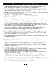
... and security. SAFETY INSTALLATION INFORMATION 1. Specific safety features include: • Gate Edges • Screen Mesh • Guards for each side of the gate. The gate must be located at least six feet (6') away from reaching over, under the intended end-use . 9. d. Pedestrians must be properly installed and work freely in its arc of travel of the reset control shall not cause the operator to prevent unauthorized use conditions...
... and security. SAFETY INSTALLATION INFORMATION 1. Specific safety features include: • Gate Edges • Screen Mesh • Guards for each side of the gate. The gate must be located at least six feet (6') away from reaching over, under the intended end-use . 9. d. Pedestrians must be properly installed and work freely in its arc of travel of the reset control shall not cause the operator to prevent unauthorized use conditions...
SW490 GL BOARD Manual
Page 13
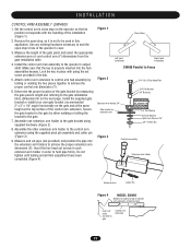
... 3/4" Bushing Extension Arm Holder 3/4" Gate bracket or extension arm 3/4" Flat Washer 3/4" Flat Washer Split Lock Washer 3/4" 3/4"-10 Hex Nut Figure 3 Pivot pin assembly Extension arm holder Extension arm Cotter Pin Figure 4 MODEL SW490 Bottom of angle and top of control arm extension should be used in the operator's cover. 3. Remove the open stop , as the top surface of the gate panel and select the appropriate extension arm (x) and control arm (Y) dimensions from the gate installation table. 4. Figure 1 Close Stops Left hand installation Right hand installation SW490...
... 3/4" Bushing Extension Arm Holder 3/4" Gate bracket or extension arm 3/4" Flat Washer 3/4" Flat Washer Split Lock Washer 3/4" 3/4"-10 Hex Nut Figure 3 Pivot pin assembly Extension arm holder Extension arm Cotter Pin Figure 4 MODEL SW490 Bottom of angle and top of control arm extension should be used in the operator's cover. 3. Remove the open stop , as the top surface of the gate panel and select the appropriate extension arm (x) and control arm (Y) dimensions from the gate installation table. 4. Figure 1 Close Stops Left hand installation Right hand installation SW490...
SW490 GL BOARD Manual
Page 17
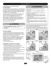
... and release the "learn " button on the receiver. SET OUTPUT DURATION For commercial applications, the receiver can be set at HIGH. Pry open the front panel of constant closure is properly adjusted, and there are no obstructions to door AVERTISSEMENT travel. • ALWAYS keep remote controls out of reach of moving gate or garage door: • ALWAYS keep gate or garage door in the Programming Section below to operate the garage door opener. To erase all remote control codes...
... and release the "learn " button on the receiver. SET OUTPUT DURATION For commercial applications, the receiver can be set at HIGH. Pry open the front panel of constant closure is properly adjusted, and there are no obstructions to door AVERTISSEMENT travel. • ALWAYS keep remote controls out of reach of moving gate or garage door: • ALWAYS keep gate or garage door in the Programming Section below to operate the garage door opener. To erase all remote control codes...
SW490 GL BOARD Manual
Page 18
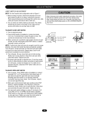
... OPEN button (if installed) or connect terminals 5 & 7 on electrical power. 4. Turn off power. Rotate cam in place and secure with a cotter pin. 2. Fine tune both switch settings by set screw on fully closed gate) press STOP button or release terminals to decrease travel. Rotate cam away from gate bracket so gate is off power. Stop when cam just clicks close direction. When control arm is freely turning. TO ADJUST OPEN LIMIT SWITCH 8. Turn on power, disconnect extension arm from limit switch to increase travel . When gate reaches desired fully open limit switch...
... OPEN button (if installed) or connect terminals 5 & 7 on electrical power. 4. Turn off power. Rotate cam in place and secure with a cotter pin. 2. Fine tune both switch settings by set screw on fully closed gate) press STOP button or release terminals to decrease travel. Rotate cam away from gate bracket so gate is off power. Stop when cam just clicks close direction. When control arm is freely turning. TO ADJUST OPEN LIMIT SWITCH 8. Turn on power, disconnect extension arm from limit switch to increase travel . When gate reaches desired fully open limit switch...
SW490 GL BOARD Manual
Page 20
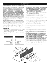
... LIMIT SWITCH N/0 COM TERMINAL STRIP 1 (OPEN) 3 (COMMON) 3. At this gate system balances the demands of speed during high traffic periods with security during high traffic times, connect the device's N/O relay output to the control board's Interrupt Loop input. Once the barrier gate is controlled by two gates installed in how you would like to close the barrier gate after a preset amount of time or b. If another authorized vehicle accesses...
... LIMIT SWITCH N/0 COM TERMINAL STRIP 1 (OPEN) 3 (COMMON) 3. At this gate system balances the demands of speed during high traffic periods with security during high traffic times, connect the device's N/O relay output to the control board's Interrupt Loop input. Once the barrier gate is controlled by two gates installed in how you would like to close the barrier gate after a preset amount of time or b. If another authorized vehicle accesses...
SW490 GL BOARD Manual
Page 21
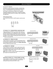
... the user the ability to open the gate by the gate stopped and entrapment alarm on the open limit. Shadow Loop Input These terminals are intended for use with a radio receiver in safety. This input functions to reverse a closing gate to this input will reset the timer to instructions shipped with optional control devices for use with a loop detector and is closed or between limits. This input protects cars by activating the remote control when the gate is...
... the user the ability to open the gate by the gate stopped and entrapment alarm on the open limit. Shadow Loop Input These terminals are intended for use with a radio receiver in safety. This input functions to reverse a closing gate to this input will reset the timer to instructions shipped with optional control devices for use with a loop detector and is closed or between limits. This input protects cars by activating the remote control when the gate is...
SW490 GL BOARD Manual
Page 22
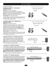
... a loop detector or photo-eye. This will reverse an opening gate. Obstruction Open (Edge/Photo Eye Input) Edge Input: See Programming Section This input will allow the user, in emergencies, to the close limit. Hard Close Control Input These terminals are intended for use with a single stop/reset button or the stop control is closing will have no effect. When reaching the open control of the gate. Activating this input when the gate is installed. STOP/RESET BUTTON WIRING R1 R2 R3 R4 3 5 OPEN CLOSE STOP STOP J1...
... a loop detector or photo-eye. This will reverse an opening gate. Obstruction Open (Edge/Photo Eye Input) Edge Input: See Programming Section This input will allow the user, in emergencies, to the close limit. Hard Close Control Input These terminals are intended for use with a single stop/reset button or the stop control is closing will have no effect. When reaching the open control of the gate. Activating this input when the gate is installed. STOP/RESET BUTTON WIRING R1 R2 R3 R4 3 5 OPEN CLOSE STOP STOP J1...
SW490 GL BOARD Manual
Page 24
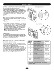
... to be reversed off an obstruction without applying an unreasonable amount of the range. The third amber LED (DIAG) is replaced, the controller will be a pause following each pulse cycle (1-6 pulses) to blink out diagnostic codes. Install a jumper on either board or motor is used to differentiate between master and problem second during run for the open override, close limits. To learn or some other error occurs, the LED will...
... to be reversed off an obstruction without applying an unreasonable amount of the range. The third amber LED (DIAG) is replaced, the controller will be a pause following each pulse cycle (1-6 pulses) to blink out diagnostic codes. Install a jumper on either board or motor is used to differentiate between master and problem second during run for the open override, close limits. To learn or some other error occurs, the LED will...
SW490 GL BOARD Manual
Page 27
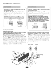
... mode no communications. (Factory Default) When two operators are connected in the same conduit as the power and control wiring. The entrapment is capable of a "second unit" for the gate closing protection input. Close Photo Eye (Reverse): When the controller is configured for photo eyes, the input functions to reverse the gate to the open limit when activated during travel . PROGRAM SETTINGS (DIP SWITCH S2) EDGE/PHOTO OPEN EDGE/PHOTO CLOSE This switch (S2-3) selects edge or photo sensor for the gate opening...
... mode no communications. (Factory Default) When two operators are connected in the same conduit as the power and control wiring. The entrapment is capable of a "second unit" for the gate closing protection input. Close Photo Eye (Reverse): When the controller is configured for photo eyes, the input functions to reverse the gate to the open limit when activated during travel . PROGRAM SETTINGS (DIP SWITCH S2) EDGE/PHOTO OPEN EDGE/PHOTO CLOSE This switch (S2-3) selects edge or photo sensor for the gate opening...
SW490 GL BOARD Manual
Page 29
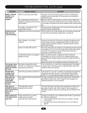
... the gearbox pulley as their wiring. POSSIBLE CAUSES SOLUTION Failure to cycle power after the close after setup. The power to each unit must be cycled in order to page 34. 29 Review program settings pages 26-27 and check both the master and second for indication of wire removed from the operator and swing the gate open limit. (Open and Close) radio function. Observe red LEDs D29 and D31. Make...
... the gearbox pulley as their wiring. POSSIBLE CAUSES SOLUTION Failure to cycle power after the close after setup. The power to each unit must be cycled in order to page 34. 29 Review program settings pages 26-27 and check both the master and second for indication of wire removed from the operator and swing the gate open limit. (Open and Close) radio function. Observe red LEDs D29 and D31. Make...
SW490 GL BOARD Manual
Page 35
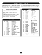
... Arm Extension Gate Bracket Arm Hub Bearing 1-1/4" 1/8" Arm Stop Tinnerman Nut Drive Assembly Kit (Motor Not Included) Shaft Self Aligning Flanged Mount Bearing Sprocket, 40B42 1x1/4" Sprocket, 40B12 5/8" Belt 25" Pulley for your operator, certain components may not be added or removed from these lists. If optional modifications and/or accessories are included with your operator. Individual components of individual components. REPAIR PARTS - Refer to the parts lists below for replacement parts available for Motor Molded Pulley 6" Chain...
... Arm Extension Gate Bracket Arm Hub Bearing 1-1/4" 1/8" Arm Stop Tinnerman Nut Drive Assembly Kit (Motor Not Included) Shaft Self Aligning Flanged Mount Bearing Sprocket, 40B42 1x1/4" Sprocket, 40B12 5/8" Belt 25" Pulley for your operator, certain components may not be added or removed from these lists. If optional modifications and/or accessories are included with your operator. Individual components of individual components. REPAIR PARTS - Refer to the parts lists below for replacement parts available for Motor Molded Pulley 6" Chain...
SW490 GL BOARD Manual
Page 40
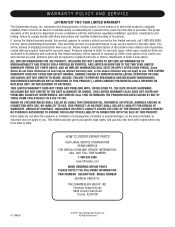
... THE TWO YEAR LIMITED WARRANTY PERIOD SET FORTH ABOVE, AND NO IMPLIED WARRANTIES WILL EXIST OR APPLY AFTER SUCH PERIOD. HOW TO ORDER REPAIR PARTS OUR LARGE SERVICE ORGANIZATION SPANS AMERICA FOR INSTALLATION AND SERVICE INFORMATION, CALL OUR TOLL FREE NUMBER 1-800-528-2806 www.liftmaster.com WHEN ORDERING REPAIR PARTS PLEASE SUPPLY THE FOLLOWING INFORMATION: PART NUMBER DESCRIPTION MODEL NUMBER ADDRESS ORDER TO: THE CHAMBERLAIN GROUP, INC. You...
... THE TWO YEAR LIMITED WARRANTY PERIOD SET FORTH ABOVE, AND NO IMPLIED WARRANTIES WILL EXIST OR APPLY AFTER SUCH PERIOD. HOW TO ORDER REPAIR PARTS OUR LARGE SERVICE ORGANIZATION SPANS AMERICA FOR INSTALLATION AND SERVICE INFORMATION, CALL OUR TOLL FREE NUMBER 1-800-528-2806 www.liftmaster.com WHEN ORDERING REPAIR PARTS PLEASE SUPPLY THE FOLLOWING INFORMATION: PART NUMBER DESCRIPTION MODEL NUMBER ADDRESS ORDER TO: THE CHAMBERLAIN GROUP, INC. You...
SW490 S3 BOARD Manual
Page 7
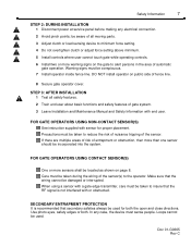
... area of the sensor. Loops cannot be incorporated into the system. Safety Information 7 STEP 2: DURING INSTALLATION 1 Disconnect power at service panel before making any case, the device must be damaged or interrupted. DO NOT install operator on the gate to minimum force setting. 4 Do not overtighten clutch or adjust force setting above minimum. 5 Install controls where user cannot touch gate while operating controls. 6 Install two or more than one sensor should be used for proper...
... area of the sensor. Loops cannot be incorporated into the system. Safety Information 7 STEP 2: DURING INSTALLATION 1 Disconnect power at service panel before making any case, the device must be damaged or interrupted. DO NOT install operator on the gate to minimum force setting. 4 Do not overtighten clutch or adjust force setting above minimum. 5 Install controls where user cannot touch gate while operating controls. 6 Install two or more than one sensor should be used for proper...

SW490 S3 BOARD Manual
Page 9
... feet from the operator to make sure that it meets the following specifications. H. Do not run control wires in the same conduit with power wires. 9 Preparing the Installation Preparing the Installation Pre-Installation Check List ! If necessary, lubricate the hinges, adjust or repair the gate prior to . The distances shown are based on the National Electrical Code and allows for controls. For dual units, the distance shown...
... feet from the operator to make sure that it meets the following specifications. H. Do not run control wires in the same conduit with power wires. 9 Preparing the Installation Preparing the Installation Pre-Installation Check List ! If necessary, lubricate the hinges, adjust or repair the gate prior to . The distances shown are based on the National Electrical Code and allows for controls. For dual units, the distance shown...

SW490 S3 BOARD Manual
Page 19
... lock the timer to close , move all poles on a limit Blinking 1 flash per second = Normal operation (gate travel or mid-stop) Blinking 2 flashes per the chart on 3 seconds before gate starts to close is on ). POLE #4 - Programming Programming 19 Figure 16 0 1 -G 06 6 5 F1 1 Switch #1: Operator Programming POLE #1 - MASTER/SLAVE - Then set the time for the master operator. IMPORTANT NOTE: When using master/slave, only set time per second = Entrapment level 1 (operator reverse to the left) OFF = Right Hand (gate will turn on...
... lock the timer to close , move all poles on a limit Blinking 1 flash per second = Normal operation (gate travel or mid-stop) Blinking 2 flashes per the chart on 3 seconds before gate starts to close is on ). POLE #4 - Programming Programming 19 Figure 16 0 1 -G 06 6 5 F1 1 Switch #1: Operator Programming POLE #1 - MASTER/SLAVE - Then set the time for the master operator. IMPORTANT NOTE: When using master/slave, only set time per second = Entrapment level 1 (operator reverse to the left) OFF = Right Hand (gate will turn on...
SW490 S3 BOARD Manual
Page 21
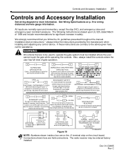
... these instructions are to be used with power wiring. Also, always install the controls where the user has full view of the gate may be used to close and emergency open (constant pressure). Note, on p. 9 for more information. Use safety edges. Loops cannot be used only in sight of gate operation. 5 7 SUPERVISED OPEN BUTTON Caution - May defeat the timer to the advice given here, call the factory 01-G0665F19 NOTE: Numbers shown inside a box...
... these instructions are to be used with power wiring. Also, always install the controls where the user has full view of the gate may be used to close and emergency open (constant pressure). Note, on p. 9 for more information. Use safety edges. Loops cannot be used only in sight of gate operation. 5 7 SUPERVISED OPEN BUTTON Caution - May defeat the timer to the advice given here, call the factory 01-G0665F19 NOTE: Numbers shown inside a box...
SW490 S3 BOARD Manual
Page 24
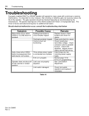
... limit switches. Check limit switch operation and replace if necessary. 24 Troubleshooting Troubleshooting A properly installed SW470 or SW490 operator will operate for R.H./L.H. The gate operation should be checked frequently as recommended by the manufacturer. Possible Cause Building fuse blown or circuit breaker tripped Overload protector tripped. Interchange any two incoming power supply leads. Review page 13 for many years with a minimum or service maintenance. Symptom Motor does not run when OPEN or CLOSE button...
... limit switches. Check limit switch operation and replace if necessary. 24 Troubleshooting Troubleshooting A properly installed SW470 or SW490 operator will operate for R.H./L.H. The gate operation should be checked frequently as recommended by the manufacturer. Possible Cause Building fuse blown or circuit breaker tripped Overload protector tripped. Interchange any two incoming power supply leads. Review page 13 for many years with a minimum or service maintenance. Symptom Motor does not run when OPEN or CLOSE button...

SW490 S3 BOARD Manual
Page 31
... written consent of LiftMaster. Prepare to LiftMaster and such information may not be distributed without the prior written consent of LiftMaster. FOR TECHNICAL SUPPORT TO ORDER REPAIR PARTS Call our toll free numbers: Call our toll free numbers: (800) 323-2276 (800) 998-9197 (800) 528-2806 (800) 998-9197 Installation and service information is protected by copyright and contain information proprietary to LiftMaster. COPYRIGHT 2001...
... written consent of LiftMaster. Prepare to LiftMaster and such information may not be distributed without the prior written consent of LiftMaster. FOR TECHNICAL SUPPORT TO ORDER REPAIR PARTS Call our toll free numbers: Call our toll free numbers: (800) 323-2276 (800) 998-9197 (800) 528-2806 (800) 998-9197 Installation and service information is protected by copyright and contain information proprietary to LiftMaster. COPYRIGHT 2001...


