LA500 Manual
Page 3
... Operator Arm to the Control Board 19 Dual Gates Only 20-21 Power Wiring 22-23 Connect Batteries 23-24 Engage the Operator 24 ADJUSTMENT 25-26 Limit and Force Adjustment 25-26 Obstruction Test 26 PROGRAMMING 27-28 Remote Controls 27 Erase All Codes 27 OPERATION 28 Manual Release 28 Reset Button 28 Remote Control 28 Party Mode 28 MAINTENANCE 29 Maintenance Chart 29 Batteries 29 ADDITIONAL FEATURES 29-35 LiftMaster Internet Gateway 29 Control Board Overview 30 Accessory Features on Control Board...
... Operator Arm to the Control Board 19 Dual Gates Only 20-21 Power Wiring 22-23 Connect Batteries 23-24 Engage the Operator 24 ADJUSTMENT 25-26 Limit and Force Adjustment 25-26 Obstruction Test 26 PROGRAMMING 27-28 Remote Controls 27 Erase All Codes 27 OPERATION 28 Manual Release 28 Reset Button 28 Remote Control 28 Party Mode 28 MAINTENANCE 29 Maintenance Chart 29 Batteries 29 ADDITIONAL FEATURES 29-35 LiftMaster Internet Gateway 29 Control Board Overview 30 Accessory Features on Control Board...
LA500 Manual
Page 5
... intended end-use . 9. One or more contact sensors shall be located at the bottom edge of the gate operator. 3 SAFETY INSTALLATION INFORMATION 8. Vehicular gate systems provide convenience and security. The pedestrian access opening and closing to the installation of a vehicular vertical lift gate. A wireless contact sensor such as when a vehicle trips the sensor while the gate is still moving part of the gate and where the user is only one that the gate covers in...
... intended end-use . 9. One or more contact sensors shall be located at the bottom edge of the gate operator. 3 SAFETY INSTALLATION INFORMATION 8. Vehicular gate systems provide convenience and security. The pedestrian access opening and closing to the installation of a vehicular vertical lift gate. A wireless contact sensor such as when a vehicle trips the sensor while the gate is still moving part of the gate and where the user is only one that the gate covers in...
LA500 Manual
Page 6
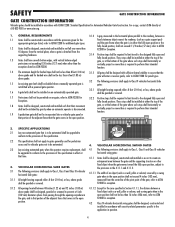
... the open position. 2. These stops shall be incorporated into a vehicular gate panel or that portion of the adjacent fence that time. 4.1.1 Gates shall be designed, constructed and installed so as not to ASTM F2200 for the appropriate gate type listed, refer to create an entrapment area between a fixed object such as a wall, pillar or column) covered by gravity when an automatic operator is...
... the open position. 2. These stops shall be incorporated into a vehicular gate panel or that portion of the adjacent fence that time. 4.1.1 Gates shall be designed, constructed and installed so as not to ASTM F2200 for the appropriate gate type listed, refer to create an entrapment area between a fixed object such as a wall, pillar or column) covered by gravity when an automatic operator is...
LA500 Manual
Page 7
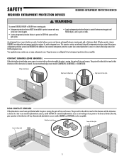
... BOTH the open and close gate cycles. • Locate entrapment protection devices to travel in that direction until the obstruction is every location or point of an external entrapment protection system (non-contact photoelectric sensor or contact safety edge sensor) for Close Cycle NON-CONTACT SENSORS If the photoelectric sensor beam gets blocked while the gate is moving, the gate will stop and reverse. Property owners are also...
... BOTH the open and close gate cycles. • Locate entrapment protection devices to travel in that direction until the obstruction is every location or point of an external entrapment protection system (non-contact photoelectric sensor or contact safety edge sensor) for Close Cycle NON-CONTACT SENSORS If the photoelectric sensor beam gets blocked while the gate is moving, the gate will stop and reverse. Property owners are also...

LA500 Manual
Page 8
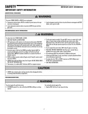
... operator power switch. Gate MUST reverse on gate will interfere with proper operation of safety reversal system. • NEVER increase force beyond minimum amount required to move gate. • NEVER use force adjustments to prevent access through openings anywhere the gate may travel limits) is adjusted, the other control may be returned to service. • Disconnect power at that you install an edge sensor BEFORE proceeding with a rigid object. 6 Non-contact sensors such as posts or walls...
... operator power switch. Gate MUST reverse on gate will interfere with proper operation of safety reversal system. • NEVER increase force beyond minimum amount required to move gate. • NEVER use force adjustments to prevent access through openings anywhere the gate may travel limits) is adjusted, the other control may be returned to service. • Disconnect power at that you install an edge sensor BEFORE proceeding with a rigid object. 6 Non-contact sensors such as posts or walls...
LA500 Manual
Page 9
... battery) BEFORE installing or servicing operator. Have a qualified service person make repairs to adjust and retest the gate operator properly can be performed until disconnecting the electrical power (AC or solar and battery) and locking-out the power via the operator power switch. Pedestrians MUST use ONLY LiftMaster part 29-NP712 for vehicles ONLY. Failure to gate hardware. • ALL maintenance MUST be on contact with gate controls. Read the owner's manual. SAFETY IMPORTANT SAFETY INFORMATION ADDITIONAL FEATURES IMPORTANT SAFETY INFORMATION...
... battery) BEFORE installing or servicing operator. Have a qualified service person make repairs to adjust and retest the gate operator properly can be performed until disconnecting the electrical power (AC or solar and battery) and locking-out the power via the operator power switch. Pedestrians MUST use ONLY LiftMaster part 29-NP712 for vehicles ONLY. Failure to gate hardware. • ALL maintenance MUST be on contact with gate controls. Read the owner's manual. SAFETY IMPORTANT SAFETY INFORMATION ADDITIONAL FEATURES IMPORTANT SAFETY INFORMATION...
LA500 Manual
Page 11
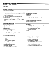
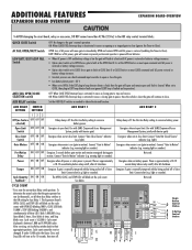
... Single Button Close (SBC): accessory connection - EXIT, SHADOW, or INTERRUPT LOOP: accessory connection EXPANSION BOARD FEATURES • Plug-in Loop Detector Connectors (Model LOOPDETLM Loop Detector) - OPEN LIMIT: ON at close limit - FIRE DEPARTMENT OPEN: accessory connection - INTEGRATED RADIO RECEIVER: • LOOPS: - SHADOW - CLOSE LIMIT: OFF at open limit switch - Secure power failure selection • SAMS compatible • Slow-start and slow-stop gate motion • Reset Button • Audible Alarm • Standard Control box has an external antenna (remote extension...
... Single Button Close (SBC): accessory connection - EXIT, SHADOW, or INTERRUPT LOOP: accessory connection EXPANSION BOARD FEATURES • Plug-in Loop Detector Connectors (Model LOOPDETLM Loop Detector) - OPEN LIMIT: ON at close limit - FIRE DEPARTMENT OPEN: accessory connection - INTEGRATED RADIO RECEIVER: • LOOPS: - SHADOW - CLOSE LIMIT: OFF at open limit switch - Secure power failure selection • SAMS compatible • Slow-start and slow-stop gate motion • Reset Button • Audible Alarm • Standard Control box has an external antenna (remote extension...
LA500 Manual
Page 20
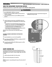
... walls. 1 Connect the entrapment protection device to the EYES EDGE terminal on page 31. TO ERASE LEARNED MONITORED PHOTOELECTRIC SENSORS 1 Remove the photoelectric sensor wires from the terminal block. 2 Press and release the SET OPEN and SET CLOSE buttons simultaneously. N.O. BOAR EARTH GROUND ROD Use the proper earth ground rod for the ground wire. The SET OPEN and SET CLOSE LEDs will be a single, whole piece of the remote controls will turn on. 3 Press and release...
... walls. 1 Connect the entrapment protection device to the EYES EDGE terminal on page 31. TO ERASE LEARNED MONITORED PHOTOELECTRIC SENSORS 1 Remove the photoelectric sensor wires from the terminal block. 2 Press and release the SET OPEN and SET CLOSE buttons simultaneously. N.O. BOAR EARTH GROUND ROD Use the proper earth ground rod for the ground wire. The SET OPEN and SET CLOSE LEDs will be a single, whole piece of the remote controls will turn on. 3 Press and release...
LA500 Manual
Page 28
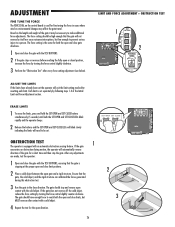
... BUTTONS, ensuring that the gate is used for both the open direction. 26 2 ! Each limit is set . EP ERASE LIMITS 1 To erase the limits, press and hold the SET OPEN and SET CLOSE buttons simultaneously (5 seconds) until both the SET OPEN and SET CLOSE LEDs blink rapidly and the operator beeps. 2 Release the buttons and the SET OPEN and SET CLOSE LEDs will blink slowly indicating the limits will exit the limit setting mode after every force setting adjustment (see below). Ensure that the gate will automatically reverse...
... BUTTONS, ensuring that the gate is used for both the open direction. 26 2 ! Each limit is set . EP ERASE LIMITS 1 To erase the limits, press and hold the SET OPEN and SET CLOSE buttons simultaneously (5 seconds) until both the SET OPEN and SET CLOSE LEDs blink rapidly and the operator beeps. 2 Release the buttons and the SET OPEN and SET CLOSE LEDs will blink slowly indicating the limits will exit the limit setting mode after every force setting adjustment (see below). Ensure that the gate will automatically reverse...
LA500 Manual
Page 29
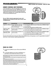
... programming mode and the remote control/keyless entry will light). 2. Press the remote control button that you would like to program. PROGRAMMING REMOTE CONTROLS (NOT PROVIDED) A total of 50 Security✚ 2.0™ remote controls and 2 keyless entries (1 PIN for compliance could void the user's authority to operate the equipment. If installing an 86LM to function. Program one remote control button as an open , close , and stop . PROGRAMMING STEPS 1. Press and release the LEARN button (operator will beep and green XMITTER LED will light). 2. Press the remote control...
... programming mode and the remote control/keyless entry will light). 2. Press the remote control button that you would like to program. PROGRAMMING REMOTE CONTROLS (NOT PROVIDED) A total of 50 Security✚ 2.0™ remote controls and 2 keyless entries (1 PIN for compliance could void the user's authority to operate the equipment. If installing an 86LM to function. Program one remote control button as an open , close , and stop . PROGRAMMING STEPS 1. Press and release the LEARN button (operator will beep and green XMITTER LED will light). 2. Press the remote control...
LA500 Manual
Page 30
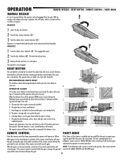
... radio receiver is low. F ! The operator is made while programming the limits press the reset button to normal operation. Pressing the reset button will close cycle, like the gate to be reset. The gate is not moving and a car pushes the gate. OPERATION MANUAL RELEASE + RESET BUTTON + REMOTE CONTROL + PARTY MODE MANUAL RELEASE In case of a power failure, the operator can be close the gate and return the operator to start over. ENGAGE 1 Turn the release lever clockwise 180°. This engages the motor. 2 Turn the key...
... radio receiver is low. F ! The operator is made while programming the limits press the reset button to normal operation. Pressing the reset button will close cycle, like the gate to be reset. The gate is not moving and a car pushes the gate. OPERATION MANUAL RELEASE + RESET BUTTON + REMOTE CONTROL + PARTY MODE MANUAL RELEASE In case of a power failure, the operator can be close the gate and return the operator to start over. ENGAGE 1 Turn the release lever clockwise 180°. This engages the motor. 2 Turn the key...
LA500 Manual
Page 32
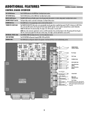
... Vdc A Single Button Control Station B Fire Dept. See Force Adjustment section. The MOVE GATE buttons will close photoelectric sensors (IR's). Always ON with gate motion. See Adjust Limits section. C Exit Loop D Shadow Loop E Interrupt Loop F Open Direction Safety G Close Direction Safety H Comm Link I Mag and J Solenoid Lock Acc. See Adjust Limits section. The Bipart delay switch is for programming remote controls and the network. The LEARN button is used only for the operator. Rotate the TIMER-TO-CLOSE dial to save L battery power if expansion board...
... Vdc A Single Button Control Station B Fire Dept. See Force Adjustment section. The MOVE GATE buttons will close photoelectric sensors (IR's). Always ON with gate motion. See Adjust Limits section. C Exit Loop D Shadow Loop E Interrupt Loop F Open Direction Safety G Close Direction Safety H Comm Link I Mag and J Solenoid Lock Acc. See Adjust Limits section. The Bipart delay switch is for programming remote controls and the network. The LEARN button is used only for the operator. Rotate the TIMER-TO-CLOSE dial to save L battery power if expansion board...
LA500 Manual
Page 34
... STOP LEDs will turn off of AC power will remain in present position and operator is activated it is at a limit until AC power is restored or batteries voltage increases. • Option select switch set Aux Relay switches back to the gate's normal operation. Cycle count displayed is restored (enabling the Timer-to stop and reverse. AC FAIL OPEN/BATT Switch OPEN: Loss of close . ANTI-TAIL OPEN/CLOSE SELECTION switch OFF: When CLOSE EYES/Interrupt loop...
... STOP LEDs will turn off of AC power will remain in present position and operator is activated it is at a limit until AC power is restored or batteries voltage increases. • Option select switch set Aux Relay switches back to the gate's normal operation. Cycle count displayed is restored (enabling the Timer-to stop and reverse. AC FAIL OPEN/BATT Switch OPEN: Loss of close . ANTI-TAIL OPEN/CLOSE SELECTION switch OFF: When CLOSE EYES/Interrupt loop...
LA500 Manual
Page 38
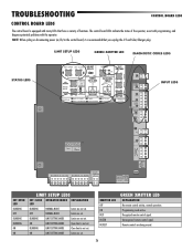
... LEDS SET CLOSE OPERATOR MODE EXPLANATION LED BLINKING NORMAL MODE Limits are not set . Recognized remote control signal. NOTE: When cycling or disconnecting power (ac/dc) to the control board, it is not set . LOCK CLASS 2 SUPPLY 24 VOLTS EXP. Programming mode active. TROUBLESHOOTING CONTROL BOARD LEDS CONTROL BOARD LEDS The control board is equipped with the operator. BLINKING LIMIT SETTING MODE Close limit is not set . Remote controls are set . LIMIT SETUP LEDS GREEN XMITTER LED DIAGNOSTIC CODES LEDS STATUS LEDS OPEN CLOSE STOP SET OPEN SET CLOSE MOVE GATE...
... LEDS SET CLOSE OPERATOR MODE EXPLANATION LED BLINKING NORMAL MODE Limits are not set . Recognized remote control signal. NOTE: When cycling or disconnecting power (ac/dc) to the control board, it is not set . LOCK CLASS 2 SUPPLY 24 VOLTS EXP. Programming mode active. TROUBLESHOOTING CONTROL BOARD LEDS CONTROL BOARD LEDS The control board is equipped with the operator. BLINKING LIMIT SETTING MODE Close limit is not set . Remote controls are set . LIMIT SETUP LEDS GREEN XMITTER LED DIAGNOSTIC CODES LEDS STATUS LEDS OPEN CLOSE STOP SET OPEN SET CLOSE MOVE GATE...
LA500 Manual
Page 39
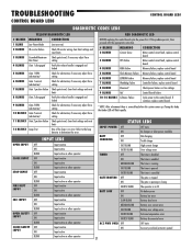
... force setting Check gate travel , if necessary adjust force setting Verify the release handle is engaged and locked BEFORE replacing the control board cycle the power first. TROUBLESHOOTING CONTROL BOARD LEDS CONTROL BOARD LEDS DIAGNOSTIC CODES LEDS YELLOW DIAGNOSTIC LED RED DIAGNOSTIC LED # BLINKS 1 BLINK 2 BLINKS MEANING Low Power Mode ID resistor failure 3 BLINKS 4 BLINKS Exceeded Maximum Run Timer Gate 1 disengaged CORRECTION (not an error) Check ID resistor wiring, clear limit settings and reset limits Check gate travel , clear limit settings and reset limits 5 BLINKS 6 BLINKS...
... force setting Check gate travel , if necessary adjust force setting Verify the release handle is engaged and locked BEFORE replacing the control board cycle the power first. TROUBLESHOOTING CONTROL BOARD LEDS CONTROL BOARD LEDS DIAGNOSTIC CODES LEDS YELLOW DIAGNOSTIC LED RED DIAGNOSTIC LED # BLINKS 1 BLINK 2 BLINKS MEANING Low Power Mode ID resistor failure 3 BLINKS 4 BLINKS Exceeded Maximum Run Timer Gate 1 disengaged CORRECTION (not an error) Check ID resistor wiring, clear limit settings and reset limits Check gate travel , clear limit settings and reset limits 5 BLINKS 6 BLINKS...
LA500 Manual
Page 41
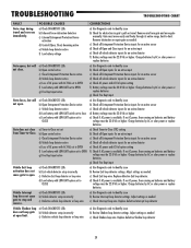
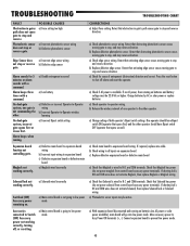
... loop detector a) Use Diagnostic code to stop and reverse. Vehicle Interrupt loop does not cause gate to identify issue b) Review Shadow loop detector settings. Remove arm from Timer-to identify issue b) Check all Entrapment Protection Device inputs for an active sensor c) Check all vehicle detector inputs for obstruction in gate's path or travel and reverses immediately. Replace defective Exit loop detector. Gate closes, but will not open. Remove obstruction or repair gate as needed . Charge batteries by AC or solar power or replace batteries a) Use Diagnostic code...
... loop detector a) Use Diagnostic code to stop and reverse. Vehicle Interrupt loop does not cause gate to identify issue b) Review Shadow loop detector settings. Remove arm from Timer-to identify issue b) Check all Entrapment Protection Device inputs for an active sensor c) Check all vehicle detector inputs for obstruction in gate's path or travel and reverses immediately. Replace defective Exit loop detector. Gate closes, but will not open. Remove obstruction or repair gate as needed . Charge batteries by AC or solar power or replace batteries a) Use Diagnostic code...
LA500 Manual
Page 42
... low power mode. Charge batteries by AC or solar power or replace batteries a) Check operator-to -Operator wireless learning a) Incorrect Bipart switch setting Expansion board function not controlling gate. Check that activating edge sensor causes moving gate to stop or reverse gate. b) Relearn the wireless network of entrapment (obstruction) detection and correct. If required, replace wire cable. Move accessory power to prevent low power mode. 40 a) With expansion board disconnected and running on expansion board. Alarm beeps three times with...
... low power mode. Charge batteries by AC or solar power or replace batteries a) Check operator-to -Operator wireless learning a) Incorrect Bipart switch setting Expansion board function not controlling gate. Check that activating edge sensor causes moving gate to stop or reverse gate. b) Relearn the wireless network of entrapment (obstruction) detection and correct. If required, replace wire cable. Move accessory power to prevent low power mode. 40 a) With expansion board disconnected and running on expansion board. Alarm beeps three times with...
LA500 Manual
Page 44
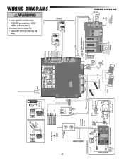
... Alarm Reset Switch Wire Loop Wire Loop Wire Loop Field Wiring EXPANSION BOARD N.C. LOCK POWER + ON + SW ACCESSORY D RESET ALARM CLA S 2 SU PLY 24 VO TS GROUND EXP BOARD Red Loop Detector Yellow Blue Black Attach to Transformer Kit (If Used) Ground White Wire Nut Black Red Black Black Red + Bridge Rectifier -- GROUND Attach to Outlet Metal Chassis With a Single Screw WIRING DIAGRAMS To protect against fire: • Replace ONLY with fuse of same type and rating. Input Power Connection N GND...
... Alarm Reset Switch Wire Loop Wire Loop Wire Loop Field Wiring EXPANSION BOARD N.C. LOCK POWER + ON + SW ACCESSORY D RESET ALARM CLA S 2 SU PLY 24 VO TS GROUND EXP BOARD Red Loop Detector Yellow Blue Black Attach to Transformer Kit (If Used) Ground White Wire Nut Black Red Black Black Red + Bridge Rectifier -- GROUND Attach to Outlet Metal Chassis With a Single Screw WIRING DIAGRAMS To protect against fire: • Replace ONLY with fuse of same type and rating. Input Power Connection N GND...
LA500 Manual
Page 46
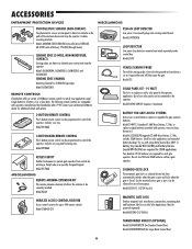
... gate or post. Model 890MAX KEYLESS ENTRY Enables homeowner to control the operator. Model LD7LP VEHICLE SENSING PROBE The vehicle sensing probe is buried in case of the electronic beam and stop the operator. Up to four solar panels can be programmed to operate gate operator from outside by Chamberlain after 1993. Model LOOPDETLM LOOP DETECTOR Low power loop detectors mounted and wired separately inside control box. Model SOLPNL10W12V (requires 2 minimum) BATTERY FOR GATE ACCESS SYSTEMS Gate access system batteries replace or upgrade the gate operator batteries. A battery tray (model...
... gate or post. Model 890MAX KEYLESS ENTRY Enables homeowner to control the operator. Model LD7LP VEHICLE SENSING PROBE The vehicle sensing probe is buried in case of the electronic beam and stop the operator. Up to four solar panels can be programmed to operate gate operator from outside by Chamberlain after 1993. Model LOOPDETLM LOOP DETECTOR Low power loop detectors mounted and wired separately inside control box. Model SOLPNL10W12V (requires 2 minimum) BATTERY FOR GATE ACCESS SYSTEMS Gate access system batteries replace or upgrade the gate operator batteries. A battery tray (model...
LA500 Manual
Page 48
... REINSTALLING A REPAIRED OR REPLACED UNIT, OR REPLACEMENT OF BATTERIES. Defective parts will be advised of purchase]. Some states do not allow the exclusion or limitation of this product, for warranty repair. All Rights Reserved This limited warranty gives you specific legal rights, and you . THIS LIMITED WARRANTY ALSO DOES NOT COVER ANY PROBLEMS CAUSED BY INTERFERENCE. WARRANTY LIFTMASTER 3 YEAR RESIDENTIAL / 2 YEAR COMMERCIAL LIMITED WARRANTY The Chamberlain Group...
... REINSTALLING A REPAIRED OR REPLACED UNIT, OR REPLACEMENT OF BATTERIES. Defective parts will be advised of purchase]. Some states do not allow the exclusion or limitation of this product, for warranty repair. All Rights Reserved This limited warranty gives you specific legal rights, and you . THIS LIMITED WARRANTY ALSO DOES NOT COVER ANY PROBLEMS CAUSED BY INTERFERENCE. WARRANTY LIFTMASTER 3 YEAR RESIDENTIAL / 2 YEAR COMMERCIAL LIMITED WARRANTY The Chamberlain Group...


