LA500 Manual
Page 1
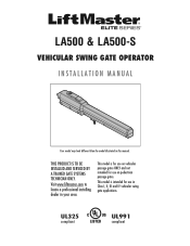
Visit www.liftmaster.com to locate a professional installing dealer in this manual. This model is for use on vehicular passage gates ONLY and not intended for use on pedestrian passage gates. This model is intended for use in Class I, II, III and IV vehicular swing gate applications. LA500 & LA500-S VEHICULAR SWING GATE OPERATOR INSTALLATION MANUAL Your model may look different than the model illustrated in your area. THIS PRODUCT IS TO BE INSTALLED AND SERVICED BY A TRAINED GATE SYSTEMS TECHNICIAN ONLY. UL325 compliant UL991 compliant
Visit www.liftmaster.com to locate a professional installing dealer in this manual. This model is for use on vehicular passage gates ONLY and not intended for use on pedestrian passage gates. This model is intended for use in Class I, II, III and IV vehicular swing gate applications. LA500 & LA500-S VEHICULAR SWING GATE OPERATOR INSTALLATION MANUAL Your model may look different than the model illustrated in your area. THIS PRODUCT IS TO BE INSTALLED AND SERVICED BY A TRAINED GATE SYSTEMS TECHNICIAN ONLY. UL325 compliant UL991 compliant
LA500 Manual
Page 3
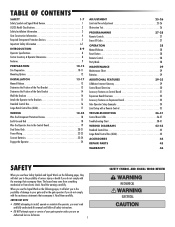
... Specifications 8 Carton Inventory & Operator Dimensions 8 Features 9 PREPARATION 10-12 Site Preparation 10-11 Mounting Options 12 INSTALLATION 13-17 Manual Release 13 Determine the Position of the Post Bracket 13 Determine the Position of the Gate Bracket 14 Weld the Brackets 14 Attach...Remote Controls 27 Erase All Codes 27 OPERATION 28 Manual Release 28 Reset Button 28 Remote Control 28 Party Mode 28 MAINTENANCE 29 Maintenance Chart 29 Batteries 29 ADDITIONAL FEATURES 29-35 LiftMaster Internet Gateway 29 Control Board Overview 30 Accessory ...
... Specifications 8 Carton Inventory & Operator Dimensions 8 Features 9 PREPARATION 10-12 Site Preparation 10-11 Mounting Options 12 INSTALLATION 13-17 Manual Release 13 Determine the Position of the Post Bracket 13 Determine the Position of the Gate Bracket 14 Weld the Brackets 14 Attach...Remote Controls 27 Erase All Codes 27 OPERATION 28 Manual Release 28 Reset Button 28 Remote Control 28 Party Mode 28 MAINTENANCE 29 Maintenance Chart 29 Batteries 29 ADDITIONAL FEATURES 29-35 LiftMaster Internet Gateway 29 Control Board Overview 30 Accessory ...
LA500 Manual
Page 5
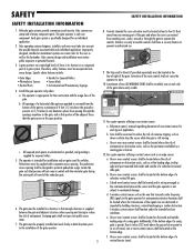
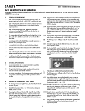
... and where the user is greater than 6 inches (152 mm) above the ground to the installation of the gate operator. 3 SAFETY INSTALLATION INFORMATION 8. Reference owner's manual regarding placement of non-contact sensor for an individual application. 2. b. Additionally, if the bottom edge of entrapment. Vehicular gate systems provide convenience and security. c. Controls...
... and where the user is greater than 6 inches (152 mm) above the ground to the installation of the gate operator. 3 SAFETY INSTALLATION INFORMATION 8. Reference owner's manual regarding placement of non-contact sensor for an individual application. 2. b. Additionally, if the bottom edge of entrapment. Vehicular gate systems provide convenience and security. c. Controls...
LA500 Manual
Page 6
... closed positions. Positive stops shall be required to limit travel to ASTM F2200 for additional gate types. An existing gate latch shall be disabled when a manually operated gate is detached from passing through the openings anywhere in the gate, and in that portion of the adjacent fence that covers in the...
... closed positions. Positive stops shall be required to limit travel to ASTM F2200 for additional gate types. An existing gate latch shall be disabled when a manually operated gate is detached from passing through the openings anywhere in the gate, and in that portion of the adjacent fence that covers in the...
LA500 Manual
Page 9
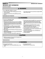
...to protect anyone who may be properly grounded and connected in BOTH the open and close gate cycles. Pedestrians MUST use ONLY LiftMaster part 29-NP712 for vehicles ONLY. Operator MUST be returned to protect in accordance with fuse of INJURY or DEATH. • Use the... manual disconnect release ONLY when the gate is not moving. • KEEP GATES PROPERLY MAINTAINED. Read the owner's manual. For continued protection against fire and electrocution: • DISCONNECT power (AC or solar and ...
...to protect anyone who may be properly grounded and connected in BOTH the open and close gate cycles. Pedestrians MUST use ONLY LiftMaster part 29-NP712 for vehicles ONLY. Operator MUST be returned to protect in accordance with fuse of INJURY or DEATH. • Use the... manual disconnect release ONLY when the gate is not moving. • KEEP GATES PROPERLY MAINTAINED. Read the owner's manual. For continued protection against fire and electrocution: • DISCONNECT power (AC or solar and ...
LA500 Manual
Page 11
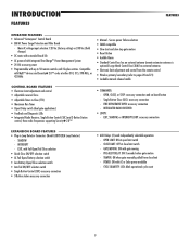
... • Programmable with AC or Solar power available - Single Button Close (SBC): accessory connection - TAMPER: ON when gate manually pulled from the remote control • Wireless primary/secondary (refer to 50 remote controls and 2 keyless entries. OPEN, CLOSE,... connection - INTEGRATED RADIO RECEIVER: • LOOPS: - INTERRUPT - POWER: ON with up to pages 20 and 21) • Lockable manual release handle • COMMANDS: - CYCLE QUANTITY: LEDs blink operational cycle count 9 INTRODUCTION FEATURES FEATURES OPERATOR FEATURES • Advanced "Centerpiece" Control...
... • Programmable with AC or Solar power available - Single Button Close (SBC): accessory connection - TAMPER: ON when gate manually pulled from the remote control • Wireless primary/secondary (refer to 50 remote controls and 2 keyless entries. OPEN, CLOSE,... connection - INTEGRATED RADIO RECEIVER: • LOOPS: - INTERRUPT - POWER: ON with up to pages 20 and 21) • Lockable manual release handle • COMMANDS: - CYCLE QUANTITY: LEDs blink operational cycle count 9 INTRODUCTION FEATURES FEATURES OPERATOR FEATURES • Advanced "Centerpiece" Control...
LA500 Manual
Page 13
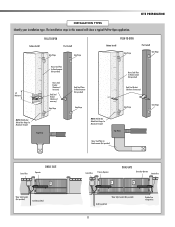
... if necessary) Gate Hinge NOTE: Weld Re Bar Behind Gate Hinges for Maximum Strength. DUAL GATE Secondary Operator Junction Box ! The installation steps in this manual will show a typical Pull-to-Open application. INSTALLATION TYPES Identify your installation type. Top View Back Steel Plates for Reinforcement (Not provided) Heavy Steel Plate...
... if necessary) Gate Hinge NOTE: Weld Re Bar Behind Gate Hinges for Maximum Strength. DUAL GATE Secondary Operator Junction Box ! The installation steps in this manual will show a typical Pull-to-Open application. INSTALLATION TYPES Identify your installation type. Top View Back Steel Plates for Reinforcement (Not provided) Heavy Steel Plate...
LA500 Manual
Page 15
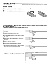
...the second measurement. 7 Align the post bracket as close as possible above the screwdriver or dowel rod and tack weld the post bracket in manual mode. Remove the Miracle-One™ operator from the previous mark. 6 Use a screwdriver to mark the location of the first measurement.... 5 Measure 8.5 inches from the brackets and proceed to the right. INSTALLATION MANUAL RELEASE + DETERMINE THE POSITION OF THE POST BRACKET MANUAL RELEASE 1 Insert the key into the lock and turn it 180 degrees counterclockwise. 2 Turn the release lever 180 degrees...
...the second measurement. 7 Align the post bracket as close as possible above the screwdriver or dowel rod and tack weld the post bracket in manual mode. Remove the Miracle-One™ operator from the previous mark. 6 Use a screwdriver to mark the location of the first measurement.... 5 Measure 8.5 inches from the brackets and proceed to the right. INSTALLATION MANUAL RELEASE + DETERMINE THE POSITION OF THE POST BRACKET MANUAL RELEASE 1 Insert the key into the lock and turn it 180 degrees counterclockwise. 2 Turn the release lever 180 degrees...
LA500 Manual
Page 30
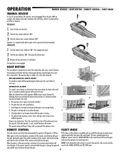
... gate. Remove any obstructions. When the gate is low. Operator is moving gate during a normal open the gate. 28 The operator is in manual mode and the gate can be opened and closed position, activation of the control box and serves several functions. ! Pressing the reset button will ...°. This engages the motor. 2 Turn the key clockwise 180°. Press the reset button to normal operation. The next command given by a LiftMaster remote control or SINGLE BUTTON on the side of the remote control button will open /close the gate. With an operator, the release action may...
... gate. Remove any obstructions. When the gate is low. Operator is moving gate during a normal open the gate. 28 The operator is in manual mode and the gate can be opened and closed position, activation of the control box and serves several functions. ! Pressing the reset button will ...°. This engages the motor. 2 Turn the key clockwise 180°. Press the reset button to normal operation. The next command given by a LiftMaster remote control or SINGLE BUTTON on the side of the remote control button will open /close the gate. With an operator, the release action may...
LA500 Manual
Page 31
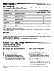
DESCRIPTION Entrapment Protection Devices Warning Signs Manual Release Gate Accessories Electrical Mounting Hardware Operator Batteries TASK Check and test for proper operation Make sure they are required for 33AH applications. The operator ... Control Box solar installation. The batteries contain lead and need to be replaced every 3 years. Create an online account by visiting www.myliftmaster.com. The LiftMaster Internet Gateway will degrade over time depending on the primary operator (the operator will beep as it enters learn mode for replacement batteries. Register the...
DESCRIPTION Entrapment Protection Devices Warning Signs Manual Release Gate Accessories Electrical Mounting Hardware Operator Batteries TASK Check and test for proper operation Make sure they are required for 33AH applications. The operator ... Control Box solar installation. The batteries contain lead and need to be replaced every 3 years. Create an online account by visiting www.myliftmaster.com. The LiftMaster Internet Gateway will degrade over time depending on the primary operator (the operator will beep as it enters learn mode for replacement batteries. Register the...
LA500 Manual
Page 34
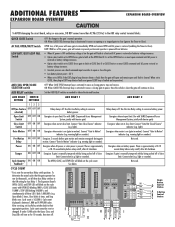
...000 cycles. There is approximately a 10-12 second delay before relay cutoff, after AC shutdown. Tamper ON OFF ON Energizes if gate is manually tampered with by being pushed off . To determine the actual cycles that the gate operator has run (in thousands), set to OPEN forces gate...will remain in present position and operator is powered from batteries. Com AUX Relay 1 N.O. BATT: With loss of close Energizes if gate is manually tampered with barrier gate) Energizes when not at open limit. Cycle Quantity ON ON ON Feedback* The OPEN, CLOSE, and STOP LEDs will ...
...000 cycles. There is approximately a 10-12 second delay before relay cutoff, after AC shutdown. Tamper ON OFF ON Energizes if gate is manually tampered with by being pushed off . To determine the actual cycles that the gate operator has run (in thousands), set to OPEN forces gate...will remain in present position and operator is powered from batteries. Com AUX Relay 1 N.O. BATT: With loss of close Energizes if gate is manually tampered with barrier gate) Energizes when not at open limit. Cycle Quantity ON ON ON Feedback* The OPEN, CLOSE, and STOP LEDs will ...
LA500 Manual
Page 36
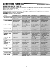
...Attach alert signal (audible or visual alert system) Attach alert signal (audible or visual alert system) Attach visual alert to know when system is manually tampered with by being pushed off of close limit Use during servicing only to ON for gate that delays upon opening 1) Use with SAMS (...CLOSE. Run on battery if AC power fails. Run on batteries) Attach alert signal (audible or visual alert system) to indicate if gate is manually tampered with by being pushed off of close (timer or control). For DUAL-GATE site, set to know when system is low, gate stays...
...Attach alert signal (audible or visual alert system) Attach alert signal (audible or visual alert system) Attach visual alert to know when system is manually tampered with by being pushed off of close limit Use during servicing only to ON for gate that delays upon opening 1) Use with SAMS (...CLOSE. Run on battery if AC power fails. Run on batteries) Attach alert signal (audible or visual alert system) to indicate if gate is manually tampered with by being pushed off of close (timer or control). For DUAL-GATE site, set to know when system is low, gate stays...
LA500 Manual
Page 40
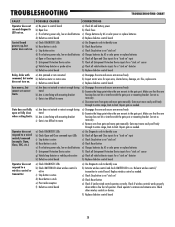
... Correct as necessary. c) Remove arm from gate and move easily and freely through its entire range, limit-to-limit. Gate must move gate manually. a) Use Diagnostic code to identify issue b) Activate wireless control and check XMITTER LED is not "stuck on" d) Check Reset button e) Charges...hit or interfere with mounting bracket c) Gate is too difficult to move easily and freely through its entire range, limit-to move gate manually. c) Check Stop button is interfering with the gate post or mounting bracket. Gate must move a) Arm does not extend or retract enough...
... Correct as necessary. c) Remove arm from gate and move easily and freely through its entire range, limit-to-limit. Gate must move gate manually. a) Use Diagnostic code to identify issue b) Activate wireless control and check XMITTER LED is not "stuck on" d) Check Reset button e) Charges...hit or interfere with mounting bracket c) Gate is too difficult to move easily and freely through its entire range, limit-to move gate manually. c) Check Stop button is interfering with the gate post or mounting bracket. Gate must move a) Arm does not extend or retract enough...
LA500 Manual
Page 41
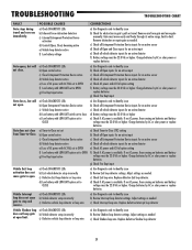
... Fail option setting f) Battery voltage must be 22.0 Vdc or higher. If no AC power, then running on batteries and battery voltage must move gate manually. d) Check if AC power is available. Vehicle Exit loop activation does not cause gate to -limit. Charge batteries by AC or solar power or replace...
... Fail option setting f) Battery voltage must be 22.0 Vdc or higher. If no AC power, then running on batteries and battery voltage must move gate manually. d) Check if AC power is available. Vehicle Exit loop activation does not cause gate to -limit. Charge batteries by AC or solar power or replace...


