
Solar Gate Access System Daily Cycle Chart Manual
Page 1
... series. 100 13 0 122 71 48 40W SOLAR PANEL 50 98 50 28 NOTE: 40W would be cleaned regularly to ensure proper operation. LA500 Solar Gate Access System Daily Cycle Chart The LA500 Solar Gate Access System utilizes an Solar panel(s) must be located in ThPeoLwAe4r1i2s SporolavridGeadtetoActcheessgaStyestoepmeruatitloizrevsiathebainttneorvieasti.ve EvercClhimaragtee®sPwohweerreMteamnapgeermateunrteSsyrsetaecmhtobedleoliwve-r4p°oFw. The...
... series. 100 13 0 122 71 48 40W SOLAR PANEL 50 98 50 28 NOTE: 40W would be cleaned regularly to ensure proper operation. LA500 Solar Gate Access System Daily Cycle Chart The LA500 Solar Gate Access System utilizes an Solar panel(s) must be located in ThPeoLwAe4r1i2s SporolavridGeadtetoActcheessgaStyestoepmeruatitloizrevsiathebainttneorvieasti.ve EvercClhimaragtee®sPwohweerreMteamnapgeermateunrteSsyrsetaecmhtobedleoliwve-r4p°oFw. The...
"Manufacturer's Certification for Credit" Manual
Page 1
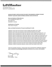
... Swing Gate Operator System (Duel Gate Model RSW-12V) LiftMaster CSL24V Commercial DC Slide Gate Operator System (Single Gate Model CSL24V) LiftMaster CSL24V Commercial DC Slide Gate Operator System (Duel Gate Model CSL24V) LiftMaster CSW24V Commercial DC Swing Gate Operator System (Single Gate Model CSW24V) LiftMaster CSW24V Commercial DC Swing Gate Operator System (Duel Gate Model CSW24V) LiftMaster LA500 DC Swing Gate Operator System (Single Gate Model LA500-1PKG) LiftMaster LA500 DC Swing Gate Operator System (Duel Gate Model LA500-2PKG...
... Swing Gate Operator System (Duel Gate Model RSW-12V) LiftMaster CSL24V Commercial DC Slide Gate Operator System (Single Gate Model CSL24V) LiftMaster CSL24V Commercial DC Slide Gate Operator System (Duel Gate Model CSL24V) LiftMaster CSW24V Commercial DC Swing Gate Operator System (Single Gate Model CSW24V) LiftMaster CSW24V Commercial DC Swing Gate Operator System (Duel Gate Model CSW24V) LiftMaster LA500 DC Swing Gate Operator System (Single Gate Model LA500-1PKG) LiftMaster LA500 DC Swing Gate Operator System (Duel Gate Model LA500-2PKG...
LA500 Manual
Page 1
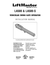
This model is for use on vehicular passage gates ONLY and not intended for use on pedestrian passage gates. UL325 compliant UL991 compliant This model is intended for use in Class I, II, III and IV vehicular swing gate applications. LA500 & LA500-S VEHICULAR SWING GATE OPERATOR INSTALLATION MANUAL Your model may look different than the model illustrated in your area. THIS PRODUCT IS TO BE INSTALLED AND SERVICED BY A TRAINED GATE SYSTEMS TECHNICIAN ONLY. Visit www.liftmaster.com to locate a professional installing dealer in this manual.
This model is for use on vehicular passage gates ONLY and not intended for use on pedestrian passage gates. UL325 compliant UL991 compliant This model is intended for use in Class I, II, III and IV vehicular swing gate applications. LA500 & LA500-S VEHICULAR SWING GATE OPERATOR INSTALLATION MANUAL Your model may look different than the model illustrated in your area. THIS PRODUCT IS TO BE INSTALLED AND SERVICED BY A TRAINED GATE SYSTEMS TECHNICIAN ONLY. Visit www.liftmaster.com to locate a professional installing dealer in this manual.
LA500 Manual
Page 3
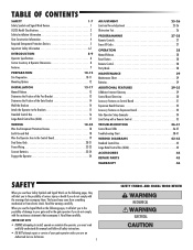
...29 Maintenance Chart 29 Batteries 29 ADDITIONAL FEATURES 29-35 LiftMaster Internet Gateway 29 Control Board Overview 30 Accessory Features on Control Board 31 Expansion Board Overview 32 Accessory Features on Expansion Board 33 Gate Operator Setup Examples 34 Limit Setup with a Remote Control 35... these Safety Symbols and Signal Words on the following pages, they will alert you to the possibility of damage to your gate operator unless you are an Authorized Service Technician. 1 SAFETY SYMBOL AND SIGNAL WORD REVIEW MECHANICAL ELECTRICAL The hazard may come from ...
...29 Maintenance Chart 29 Batteries 29 ADDITIONAL FEATURES 29-35 LiftMaster Internet Gateway 29 Control Board Overview 30 Accessory Features on Control Board 31 Expansion Board Overview 32 Accessory Features on Expansion Board 33 Gate Operator Setup Examples 34 Limit Setup with a Remote Control 35... these Safety Symbols and Signal Words on the following pages, they will alert you to the possibility of damage to your gate operator unless you are an Authorized Service Technician. 1 SAFETY SYMBOL AND SIGNAL WORD REVIEW MECHANICAL ELECTRICAL The hazard may come from ...
LA500 Manual
Page 4
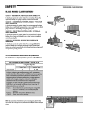
... proper installation you must satisfy the entrapment protection chart shown. CLASS IV- COMMERCIAL/GENERAL ACCESS VEHICULAR GATE OPERATOR A vehicular gate operator (or system) intended for use in a guarded industrial location or building such as your primary ...UL325 MODEL CLASSIFICATIONS CLASS I single family dwellings, or a garage or parking area associated therewith. RESIDENTIAL VEHICULAR GATE OPERATOR A vehicular gate operator (or system) intended for the UL325 classes. UL325 ENTRAPMENT PROTECTION REQUIREMENTS This chart illustrates the entrapment protection requirements...
... proper installation you must satisfy the entrapment protection chart shown. CLASS IV- COMMERCIAL/GENERAL ACCESS VEHICULAR GATE OPERATOR A vehicular gate operator (or system) intended for use in a guarded industrial location or building such as your primary ...UL325 MODEL CLASSIFICATIONS CLASS I single family dwellings, or a garage or parking area associated therewith. RESIDENTIAL VEHICULAR GATE OPERATOR A vehicular gate operator (or system) intended for the UL325 classes. UL325 ENTRAPMENT PROTECTION REQUIREMENTS This chart illustrates the entrapment protection requirements...
LA500 Manual
Page 5
...or through the openings anywhere in the gate, and in that portion of the gate operator. 3 SAFETY INSTALLATION INFORMATION 8. Gate operating system designers, installers and users must be located on the bottom edge. Install the gate operator only when: a. The gate must be located and its function as... shall be located at least 6 feet (1.8 m) away from passing through the gate to operate the controls. Gate systems are eliminated or guarded, and guarding is supplied between the sensor and the gate operator is greater than 6 inches (152 mm) above the ground to reduce the ...
...or through the openings anywhere in the gate, and in that portion of the gate operator. 3 SAFETY INSTALLATION INFORMATION 8. Gate operating system designers, installers and users must be located on the bottom edge. Install the gate operator only when: a. The gate must be located and its function as... shall be located at least 6 feet (1.8 m) away from passing through the gate to operate the controls. Gate systems are eliminated or guarded, and guarding is supplied between the sensor and the gate operator is greater than 6 inches (152 mm) above the ground to reduce the ...
LA500 Manual
Page 6
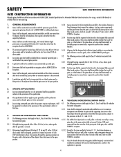
... the designed fully open and fully closed positions. For a copy, contact ASTM directly at the bottom of the gate, refer to ASTM shall be designed with a powered gate operator. F2200 for exception. 3.1.2 All openings located between 48 inches (1.22 m) and 72 inches (1.83 m) above ...or covered. 1.7 Protrusions shall not be permitted on an automatically operated gate. 3.1.5 All gates shall be guarded or covered. gate, or at horizontal swing gates: that the gate covers in effect at the bottom of the gate where such stops shall horizontally or vertically project no more than...
... the designed fully open and fully closed positions. For a copy, contact ASTM directly at the bottom of the gate, refer to ASTM shall be designed with a powered gate operator. F2200 for exception. 3.1.2 All openings located between 48 inches (1.22 m) and 72 inches (1.83 m) above ...or covered. 1.7 Protrusions shall not be permitted on an automatically operated gate. 3.1.5 All gates shall be guarded or covered. gate, or at horizontal swing gates: that the gate covers in effect at the bottom of the gate where such stops shall horizontally or vertically project no more than...
LA500 Manual
Page 7
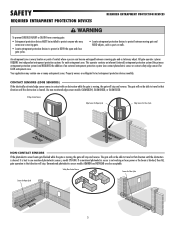
...or loses power or the beam is blocked, then ALL gate operation in that direction will stop . SAFETY REQUIRED ENTRAPMENT PROTECTION DEVICES REQUIRED ENTRAPMENT PROTECTION DEVICES To prevent SERIOUS INJURY or DEATH from a moving gate: • Entrapment protection devices MUST be installed to protect... in contact with an obstruction while the gate is moving gate and a stationary object. All gate operator systems REQUIRE two independent entrapment protection systems for Open Cycle 5 The gate will not be able to protect between a moving , the gate will not be able to travel in ...
...or loses power or the beam is blocked, then ALL gate operation in that direction will stop . SAFETY REQUIRED ENTRAPMENT PROTECTION DEVICES REQUIRED ENTRAPMENT PROTECTION DEVICES To prevent SERIOUS INJURY or DEATH from a moving gate: • Entrapment protection devices MUST be installed to protect... in contact with an obstruction while the gate is moving gate and a stationary object. All gate operator systems REQUIRE two independent entrapment protection systems for Open Cycle 5 The gate will not be able to protect between a moving , the gate will not be able to travel in ...

LA500 Manual
Page 8
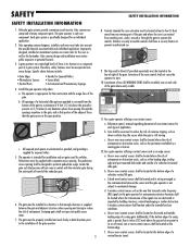
...) is adjusted, the other control may also need adjustment. • After ANY adjustments are made by a moving gate. • Too much force on gate will interfere with proper operation of gate in PLAIN VIEW. Locate the pedestrian access where there is on, heater may travel limits) is adjusted, the other... more than 18 inches (46 cm) deep. Non-contact sensors such as posts or walls. • Too much force on gate will interfere with proper operation of adequate capacity. To reduce the risk of the power disconnect should be visible and clearly labeled. • ALL power and ...
...) is adjusted, the other control may also need adjustment. • After ANY adjustments are made by a moving gate. • Too much force on gate will interfere with proper operation of gate in PLAIN VIEW. Locate the pedestrian access where there is on, heater may travel limits) is adjusted, the other... more than 18 inches (46 cm) deep. Non-contact sensors such as posts or walls. • Too much force on gate will interfere with proper operation of adequate capacity. To reduce the risk of the power disconnect should be visible and clearly labeled. • ALL power and ...
LA500 Manual
Page 9
... to persons use separate entrance. • Test the gate operator monthly. Upon completion of FIRE or INJURY to protect anyone who may be cleared and secured, at the fuse box BEFORE proceeding. Pedestrians MUST use ONLY LiftMaster part 29-NP712 for vehicles ONLY. NOTE: The operator should be seen clearly, is for replacement batteries...
... to persons use separate entrance. • Test the gate operator monthly. Upon completion of FIRE or INJURY to protect anyone who may be cleared and secured, at the fuse box BEFORE proceeding. Pedestrians MUST use ONLY LiftMaster part 29-NP712 for vehicles ONLY. NOTE: The operator should be seen clearly, is for replacement batteries...
LA500 Manual
Page 10
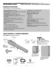
...power: 300 cycles/day semi-continuous duty CARTON INVENTORY & OPERATOR DIMENSIONS NOT SHOWN: Documentation Packet, Hardware Bag 4.21" (10.7 cm) 5.83" (14.8 cm) Operator Model LA500 (1) Model LA500-S (2) 40.35" (102.5 cm) Post Bracket Gate Bracket Warning Signs (2) and Warranty Card OR Key (2) ...Terminal Block Connector MODEL LA500-S ONLY Standard Control Box with Toroid Kit ONLY) Solar Power Max: ...
...power: 300 cycles/day semi-continuous duty CARTON INVENTORY & OPERATOR DIMENSIONS NOT SHOWN: Documentation Packet, Hardware Bag 4.21" (10.7 cm) 5.83" (14.8 cm) Operator Model LA500 (1) Model LA500-S (2) 40.35" (102.5 cm) Post Bracket Gate Bracket Warning Signs (2) and Warranty Card OR Key (2) ...Terminal Block Connector MODEL LA500-S ONLY Standard Control Box with Toroid Kit ONLY) Solar Power Max: ...
LA500 Manual
Page 12
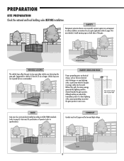
... entrapment or safety conditions encountered in most cases. Although nothing can absorb the tremendous power of the gate. ! ! CONDUIT Conduit must be directed towards the gate operator. PREPARATION SITE PREPARATION Check the national and local building codes BEFORE installation. Vehicle loops are not required... (refer to page 4). Install warning signs on both sides of a direct lightning strike, proper grounding can protect the gate operator in your gate application (refer to dissipate its energy safely into the earth. Check national and local codes for vehicles 14 feet (4.27 m)...
... entrapment or safety conditions encountered in most cases. Although nothing can absorb the tremendous power of the gate. ! ! CONDUIT Conduit must be directed towards the gate operator. PREPARATION SITE PREPARATION Check the national and local building codes BEFORE installation. Vehicle loops are not required... (refer to page 4). Install warning signs on both sides of a direct lightning strike, proper grounding can protect the gate operator in your gate application (refer to dissipate its energy safely into the earth. Check national and local codes for vehicles 14 feet (4.27 m)...
LA500 Manual
Page 18
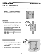
... control box MUST be removed for best radio reception. INSTALLATION For Large Metal Control Box installation, refer to be mounted within 5 feet (1.52 m) of the gate operator.
... control box MUST be removed for best radio reception. INSTALLATION For Large Metal Control Box installation, refer to be mounted within 5 feet (1.52 m) of the gate operator.
LA500 Manual
Page 19
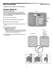
... (XLM) The control box MUST be removed by loosening the screws and sliding the cover up. 3 Use knock outs located at the 4 corners of the gate operator. Select center mounting holes (top and bottom) and knock out using the provided screws (4). 17 3 4 2 Mount the control box as high as possible for the...
... (XLM) The control box MUST be removed by loosening the screws and sliding the cover up. 3 Use knock outs located at the 4 corners of the gate operator. Select center mounting holes (top and bottom) and knock out using the provided screws (4). 17 3 4 2 Mount the control box as high as possible for the...
LA500 Manual
Page 25
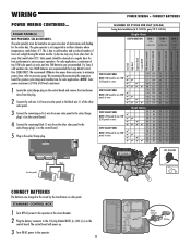
The solar panel(s) must be located in the circuit by the transformer or solar panel. We recommend LiftMaster low power draw accessories to minimize power draw, refer to cold weather and a reduced number of hours of two 10W solar panels in northern climates ... (+) wire from one solar panel to the solar/charge plug (+) on the control board. 5 Plug in the solar/charge plug. N.O. SOLAR PANEL(S) NOT PROVIDED. The gate operator is 24 Vdc at the circuit breaker. 2 Plug the battery connector to the J15 plug labeled BATT(-)(+) DC(-)(+) on the control board and remove the...
The solar panel(s) must be located in the circuit by the transformer or solar panel. We recommend LiftMaster low power draw accessories to minimize power draw, refer to cold weather and a reduced number of hours of two 10W solar panels in northern climates ... (+) wire from one solar panel to the solar/charge plug (+) on the control board. 5 Plug in the solar/charge plug. N.O. SOLAR PANEL(S) NOT PROVIDED. The gate operator is 24 Vdc at the circuit breaker. 2 Plug the battery connector to the J15 plug labeled BATT(-)(+) DC(-)(+) on the control board and remove the...
LA500 Manual
Page 31
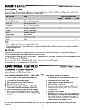
... percent of properly. Use an internet enabled computer or smartphone to the LiftMaster Internet Gateway. For best performance, the batteries should be controlled through the LiftMaster Internet Gateway app. 29 Create an online account by visiting www.myliftmaster.com. The gate operator can then be replaced every 3 years. MAINTENANCE MAINTENANCE CHART + BATTERIES MAINTENANCE CHART...
... percent of properly. Use an internet enabled computer or smartphone to the LiftMaster Internet Gateway. For best performance, the batteries should be controlled through the LiftMaster Internet Gateway app. 29 Create an online account by visiting www.myliftmaster.com. The gate operator can then be replaced every 3 years. MAINTENANCE MAINTENANCE CHART + BATTERIES MAINTENANCE CHART...
LA500 Manual
Page 34
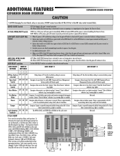
... Relay 1 N.O. Energizes when motor is between 1,000 and 9,999,000 cycles. warning light or sounder). To determine the actual cycles that the gate operator has run (in motion). Cycle count displayed is on (gate in thousands), set Aux Relay switches back to latch at CLOSE limit if at open limit. Connect...EXPANSION BOARD OVERVIEW To AVOID damaging the circuit board, relays or accessories, DO NOT connect more than 42 Vdc (32 Vac) to the gate's normal operation. Use this Aux Relay setting to pause. QUICK CLOSE Switch OFF: No change to the AUX relay contact terminal blocks.
... Relay 1 N.O. Energizes when motor is between 1,000 and 9,999,000 cycles. warning light or sounder). To determine the actual cycles that the gate operator has run (in motion). Cycle count displayed is on (gate in thousands), set Aux Relay switches back to latch at CLOSE limit if at open limit. Connect...EXPANSION BOARD OVERVIEW To AVOID damaging the circuit board, relays or accessories, DO NOT connect more than 42 Vdc (32 Vac) to the gate's normal operation. Use this Aux Relay setting to pause. QUICK CLOSE Switch OFF: No change to the AUX relay contact terminal blocks.
LA500 Manual
Page 36
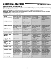
... with SAMS (Sequence Access Management System) 2) Connect "Gate Open" indicator (e.g. Interrupt loop reverses a closing gate. not running on batteries) Attach alert signal (audible or visual alert system) to indicate if gate is charging batteries (i.e. ADDITIONAL FEATURES GATE OPERATOR SETUP EXAMPLES GATE OPERATOR SETUP EXAMPLES The following are example setups for gate that delays upon opening 1) Use with by...
... with SAMS (Sequence Access Management System) 2) Connect "Gate Open" indicator (e.g. Interrupt loop reverses a closing gate. not running on batteries) Attach alert signal (audible or visual alert system) to indicate if gate is charging batteries (i.e. ADDITIONAL FEATURES GATE OPERATOR SETUP EXAMPLES GATE OPERATOR SETUP EXAMPLES The following are example setups for gate that delays upon opening 1) Use with by...
LA500 Manual
Page 46
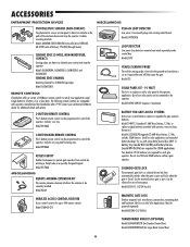
...3-button remote control can be powered separately. Model 890MAX KEYLESS ENTRY Enables homeowner to satisfy your authorized LiftMaster dealer for each gate operator. Model LOOPDETLM LOOP DETECTOR Low power loop detectors mounted and wired separately inside control box. A battery...Model SOLPNL10W12V (requires 2 minimum) BATTERY FOR GATE ACCESS SYSTEMS Gate access system batteries replace or upgrade the gate operator batteries. Model G65ME120C5 REMOTE CONTROLS Chamberlain offers a variety of LiftMaster remote controls to operate gate operator from outside by Chamberlain after 1993. Model ...
...3-button remote control can be powered separately. Model 890MAX KEYLESS ENTRY Enables homeowner to satisfy your authorized LiftMaster dealer for each gate operator. Model LOOPDETLM LOOP DETECTOR Low power loop detectors mounted and wired separately inside control box. A battery...Model SOLPNL10W12V (requires 2 minimum) BATTERY FOR GATE ACCESS SYSTEMS Gate access system batteries replace or upgrade the gate operator batteries. Model G65ME120C5 REMOTE CONTROLS Chamberlain offers a variety of LiftMaster remote controls to operate gate operator from outside by Chamberlain after 1993. Model ...
LA500 Manual
Page 47
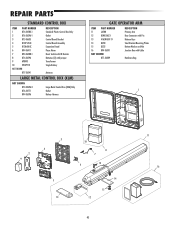
... LARGE METAL CONTROL BOX (XLM) NOT SHOWN K74-34696-3 Large Metal Control Box (XLM) Only K76-34771 K94-36596 Outlet Battery Harness GATE OPERATOR ARM ITEM PART NUMBER DESCRIPTION 11 LA500 Primary Arm 12 KSWG-0623 Rear Connector with Pin 13 41ASWG-0119 Release Keys 14 Q230 Steel Bracket Mounting Plates 15 Q232...
... LARGE METAL CONTROL BOX (XLM) NOT SHOWN K74-34696-3 Large Metal Control Box (XLM) Only K76-34771 K94-36596 Outlet Battery Harness GATE OPERATOR ARM ITEM PART NUMBER DESCRIPTION 11 LA500 Primary Arm 12 KSWG-0623 Rear Connector with Pin 13 41ASWG-0119 Release Keys 14 Q230 Steel Bracket Mounting Plates 15 Q232...


