
Setup Guide
Page 8
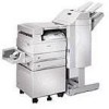
... without manual feeding. Optional envelope feeder Lets you print envelopes without using the printer trays. Optional 3250-sheet finisher with two 500-sheet trays. Either this book. Either the optional mailbox or the optional finisher may be attached to the printer. Instructions...feeder may be attached to the printer. Optional 2500-sheet high capacity feeder Significantly increases the printer input capacity. viii Preface Either the optional finisher or the optional mailbox may be attached to the printer. Lexmark W820 printer Comes standard with transport unit ...
... without manual feeding. Optional envelope feeder Lets you print envelopes without using the printer trays. Optional 3250-sheet finisher with two 500-sheet trays. Either this book. Either the optional mailbox or the optional finisher may be attached to the printer. Instructions...feeder may be attached to the printer. Optional 2500-sheet high capacity feeder Significantly increases the printer input capacity. viii Preface Either the optional finisher or the optional mailbox may be attached to the printer. Lexmark W820 printer Comes standard with transport unit ...

User's Guide
Page 271
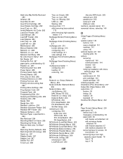
...Be Restored I Infrared Insert Box M Insert Print Cartridge Insert Staple Cartridge Insert Tray Invalid Network Code J K L Load Env Feeder Load Manual Load MP Feeder Load Staples Load Tray LocalTalk M Maintenance 269 Menus Disabled N Network Card Busy Network Network . Reformat? A Activating Menu ...Changes B Bin Full Box M Full Box M Missing Box M Near Full Busy C Canceling Job Change Tray Check Finisher Installation Check Paper Guide Clearing Job Accounting Stat Close Cover Close Deflector G Close Door D Defragmenting Delete All Jobs Deleting Jobs Disabling Menus Disk ...
...Be Restored I Infrared Insert Box M Insert Print Cartridge Insert Staple Cartridge Insert Tray Invalid Network Code J K L Load Env Feeder Load Manual Load MP Feeder Load Staples Load Tray LocalTalk M Maintenance 269 Menus Disabled N Network Card Busy Network Network . Reformat? A Activating Menu ...Changes B Bin Full Box M Full Box M Missing Box M Near Full Busy C Canceling Job Change Tray Check Finisher Installation Check Paper Guide Clearing Job Accounting Stat Close Cover Close Deflector G Close Door D Defragmenting Delete All Jobs Deleting Jobs Disabling Menus Disk ...
User's Guide
Page 328
...tray 5 80 messages, understanding 63 paper path 63 with duplex unit attached 64 with envelope feeder attached 65 with finisher attached 67 with mailbox attached 66 removing trays for access 78 from printer 78 removing trays from high capacity output feeder 78 tray 3 78 tray 4 79 326 Held Jobs May Not... Be Restored 280 Infrared 281 Insert Box M 281 Insert Print Cartridge 281 Insert Staple Cartridge 282 Insert Tray 282 Invalid Network Code 282 Load Env Feeder 283 Load Manual 283...
...tray 5 80 messages, understanding 63 paper path 63 with duplex unit attached 64 with envelope feeder attached 65 with finisher attached 67 with mailbox attached 66 removing trays for access 78 from printer 78 removing trays from high capacity output feeder 78 tray 3 78 tray 4 79 326 Held Jobs May Not... Be Restored 280 Infrared 281 Insert Box M 281 Insert Print Cartridge 281 Insert Staple Cartridge 282 Insert Tray 282 Invalid Network Code 282 Load Env Feeder 283 Load Manual 283...

Service Manual
Page 1
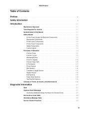
LexmarkTM W820 Finisher 4025-XXX • Table of Contents • Start Diagnostics • Safety and Notices • Trademarks • Index • Manuals Menu Lexmark and Lexmark with diamond design are trademarks of Lexmark International, Inc., registered in the United States and/or other countries.
LexmarkTM W820 Finisher 4025-XXX • Table of Contents • Start Diagnostics • Safety and Notices • Trademarks • Index • Manuals Menu Lexmark and Lexmark with diamond design are trademarks of Lexmark International, Inc., registered in the United States and/or other countries.
Service Manual
Page 3
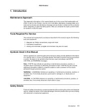
... x Introduction 1-1 Maintenance Approach 1-1 Tools Required For Service 1-1 Symbols Used in this Manual 1-1 Safety Details 1-1 Printer Power Supply and Electrical Components 1-2 Mechanical Components 1-2 Printer Laser Components 1-2 Printer Fuser Components 1-3 Safety Components 1-3 Caution Labels 1-3 Principles of Operation 1-4 Finisher Power 1-4 Finisher Control 1-5 Mechanical Drive 1-7 Drive for Jogging 1-19 Finisher Paper Path 1-26 H-Tra Section 1-27 Punch Section 1-28 Shift Section 1-32...
... x Introduction 1-1 Maintenance Approach 1-1 Tools Required For Service 1-1 Symbols Used in this Manual 1-1 Safety Details 1-1 Printer Power Supply and Electrical Components 1-2 Mechanical Components 1-2 Printer Laser Components 1-2 Printer Fuser Components 1-3 Safety Components 1-3 Caution Labels 1-3 Principles of Operation 1-4 Finisher Power 1-4 Finisher Control 1-5 Mechanical Drive 1-7 Drive for Jogging 1-19 Finisher Paper Path 1-26 H-Tra Section 1-27 Punch Section 1-28 Shift Section 1-32...

Service Manual
Page 9
... Information provides instructions for individual FRUs. Parts Catalog contains illustrations and part numbers for making printer adjustments and removing and installing FRUs. 5. Preface 4025-Finisher This manual describes the Lexmark TM W820 4025-XXX Finisher and contains maintenance procedures for the Lexmark W820 (4025) Finisher. 7. Preventive Maintenance - There are listed in this chapter, as well as general environmental and...
... Information provides instructions for individual FRUs. Parts Catalog contains illustrations and part numbers for making printer adjustments and removing and installing FRUs. 5. Preface 4025-Finisher This manual describes the Lexmark TM W820 4025-XXX Finisher and contains maintenance procedures for the Lexmark W820 (4025) Finisher. 7. Preventive Maintenance - There are listed in this chapter, as well as general environmental and...
Service Manual
Page 13
...4025-Finisher Maintenance Approach The diagnostic information in this Manual Various symbols are used throughout this manual leads you to warn of all safety instructions to repair the failing option. Tools Required For Service The removal and replacement procedures described in this manual ...error code service checks and attendance message service checks to determine the corrective action necessary to prevent accidents while servicing the printer and attached options. WARNING: A WARNING indicates an operating or maintenance procedure, practice, or condition that are present when...
...4025-Finisher Maintenance Approach The diagnostic information in this Manual Various symbols are used throughout this manual leads you to warn of all safety instructions to repair the failing option. Tools Required For Service The removal and replacement procedures described in this manual ...error code service checks and attendance message service checks to determine the corrective action necessary to prevent accidents while servicing the printer and attached options. WARNING: A WARNING indicates an operating or maintenance procedure, practice, or condition that are present when...

Service Manual
Page 14
.... 4025-Finisher Printer Power Supply and Electrical Components Before starting any electrical component unless you are instructed to do so by a service procedure. CAUTION: Do not touch any service procedure, switch off the printer power and unplug the power cord from the wall outlet. Mechanical Components Manually rotate drive assemblies to the laser beam may...
.... 4025-Finisher Printer Power Supply and Electrical Components Before starting any electrical component unless you are instructed to do so by a service procedure. CAUTION: Do not touch any service procedure, switch off the printer power and unplug the power cord from the wall outlet. Mechanical Components Manually rotate drive assemblies to the laser beam may...

Service Manual
Page 16
... these voltages to run internal logic, sensors, clutches, and motors within the Finisher. 1-4 Service Manual 4025-Finisher Principles of Operation Finisher Power The Base Engine supplies 120VAC to the Finisher, and the Finisher Power Supply converts it into a grounded AC electrical outlet. The printer AC power cord plugs into 24VDC and 5VDC that are necessary for the...
... these voltages to run internal logic, sensors, clutches, and motors within the Finisher. 1-4 Service Manual 4025-Finisher Principles of Operation Finisher Power The Base Engine supplies 120VAC to the Finisher, and the Finisher Power Supply converts it into a grounded AC electrical outlet. The printer AC power cord plugs into 24VDC and 5VDC that are necessary for the...
Service Manual
Page 20
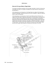
... Roller. Drive Gear 3 rotates the Drive Gear 4. The rotation of the Main Drive Gear transmits a driving force to the entire H-Tra Drive. 1-8 Service Manual The Drive Gear 4 also transmits a driving force to the Transport Gear, and then the Transport Gear transmits a driving force to the Feed Gear 1. In ... the Fin Input Roller and the H-Tra Drive, the rotation of the Feed Gear 1 transmits a driving force to the Main Drive Gear. 4025-Finisher Drive for Fin Input Roller & Regi Roller The rotation of the Main Feed Motor drives the Main Drive Belt to transmit a driving force to the...
... Roller. Drive Gear 3 rotates the Drive Gear 4. The rotation of the Main Drive Gear transmits a driving force to the entire H-Tra Drive. 1-8 Service Manual The Drive Gear 4 also transmits a driving force to the Transport Gear, and then the Transport Gear transmits a driving force to the Feed Gear 1. In ... the Fin Input Roller and the H-Tra Drive, the rotation of the Feed Gear 1 transmits a driving force to the Main Drive Gear. 4025-Finisher Drive for Fin Input Roller & Regi Roller The rotation of the Main Feed Motor drives the Main Drive Belt to transmit a driving force to the...

Service Manual
Page 22
... a driving force to the Punch Gear 1 via the Punch Gear 2. The driving force from the Regi Roll Gear is transmitted to the Feed Gear 1. 4025-Finisher Drive for Punch Unit The rotation of the Feed Gear 1 drives the Timing Belt 1, and driving the Timing Belt 1 rotates the Regi Roll Gear. The... Punch Shaft in the Punch Unit to the Main Drive Gear. The rotation of the Punch Motor moves up and down the shaft. 1-10 Service Manual
... a driving force to the Punch Gear 1 via the Punch Gear 2. The driving force from the Regi Roll Gear is transmitted to the Feed Gear 1. 4025-Finisher Drive for Punch Unit The rotation of the Feed Gear 1 drives the Timing Belt 1, and driving the Timing Belt 1 rotates the Regi Roll Gear. The... Punch Shaft in the Punch Unit to the Main Drive Gear. The rotation of the Punch Motor moves up and down the shaft. 1-10 Service Manual
Service Manual
Page 24
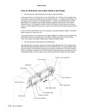
... Pulley transmits a driving force to the Main Paddle Gear via the Shift Roller. 4025-Finisher Drive for Shift Roller Unit & Main Paddle & Sub Paddle • The driving force transmitted by the Shift Handle The Shift Handle is manually rotated to rotate the Shift Roller. At the same time, the rotation of the... the Shift Transmit Pulley transmits a driving force to rotate the Shift Roller. The rotation of the Sub Transmit Pulley rotates the Sub Paddle. 1-12 Service Manual Then, the rotation of the Shift Motor moves up or down the unit.
... Pulley transmits a driving force to the Main Paddle Gear via the Shift Roller. 4025-Finisher Drive for Shift Roller Unit & Main Paddle & Sub Paddle • The driving force transmitted by the Shift Handle The Shift Handle is manually rotated to rotate the Shift Roller. At the same time, the rotation of the... the Shift Transmit Pulley transmits a driving force to rotate the Shift Roller. The rotation of the Sub Transmit Pulley rotates the Sub Paddle. 1-12 Service Manual Then, the rotation of the Shift Motor moves up or down the unit.
Service Manual
Page 26
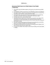
And it also transmits the driving force transmitted from the Shift Handle Gear to the Shift Transmit Pulley, when rotating the Shift Handle manually. • The Shift Transmit Pulley transmits the driving force transmitted from the Shift Roll Gear 2 to the Paddle Drive Belt via the .... • The Paddle Drive Belt transmits the driving force generated from the rotation of the Shift Transmit Pulley to the Shift Transmit Gear. 4025-Finisher Mechanical Shift Roller Unit & Main Paddle & Sub Paddle Components • The Compiler Tray Feed Motor supplies a driving force to the Shift Roller ...
And it also transmits the driving force transmitted from the Shift Handle Gear to the Shift Transmit Pulley, when rotating the Shift Handle manually. • The Shift Transmit Pulley transmits the driving force transmitted from the Shift Roll Gear 2 to the Paddle Drive Belt via the .... • The Paddle Drive Belt transmits the driving force generated from the rotation of the Shift Transmit Pulley to the Shift Transmit Gear. 4025-Finisher Mechanical Shift Roller Unit & Main Paddle & Sub Paddle Components • The Compiler Tray Feed Motor supplies a driving force to the Shift Roller ...

Service Manual
Page 28
...the Compiler Drive Shaft. The Compiler Move Tray is pushed out toward the paper delivery direction by the transmitted driving force. 1-16 Service Manual Also, the Exit Motor rotates counterclockwise when drawing the paper into the Compiler Tray. • The driving force transmitted to the Compiler ...Move Tray The counterclockwise rotation of the Exit Motor transmits a driving force to the Exit Roll Gear. 4025-Finisher Drive for Exit 2: Exit Roller & Compiler Tray • The driving force transmitted to the Exit Roller The rotation of the Exit Motor...
...the Compiler Drive Shaft. The Compiler Move Tray is pushed out toward the paper delivery direction by the transmitted driving force. 1-16 Service Manual Also, the Exit Motor rotates counterclockwise when drawing the paper into the Compiler Tray. • The driving force transmitted to the Compiler ...Move Tray The counterclockwise rotation of the Exit Motor transmits a driving force to the Exit Roll Gear. 4025-Finisher Drive for Exit 2: Exit Roller & Compiler Tray • The driving force transmitted to the Exit Roller The rotation of the Exit Motor...

Service Manual
Page 30
4025-Finisher Mechanical Drive Exit 2: Exit Roller & Compiler Move Tray Components • The Exit Motor supplies a driving force to the Exit Roller. • The Exit Roll Gear ... to the gear on the back of the Compiler Drive Shaft transmits a driving force to move the Compiler Move Tray forward or backward. 1-18 Service Manual The Com Transmit Gear transmits the driving force transmitted from the Compiler Drive Pulley to the Com Drive Gear 1. • The Com Drive Gear 1 rotates...
4025-Finisher Mechanical Drive Exit 2: Exit Roller & Compiler Move Tray Components • The Exit Motor supplies a driving force to the Exit Roller. • The Exit Roll Gear ... to the gear on the back of the Compiler Drive Shaft transmits a driving force to move the Compiler Move Tray forward or backward. 1-18 Service Manual The Com Transmit Gear transmits the driving force transmitted from the Compiler Drive Pulley to the Com Drive Gear 1. • The Com Drive Gear 1 rotates...

Service Manual
Page 32
... to the Sector Gear in the Stapler Unit, and the Sector Gear swings the Stapler Unit toward +45° or -45° direction. 1-20 Service Manual The rotation of the Stapler Drive Pulley drives the Stapler Timing Belt to move the Stapler Unit to the Stapler Drive Pulley. Then, the Stapler... Swing Gear 2 transmits a driving force to the Stapler Swing Gear 1. 4025-Finisher Drive for Staple The Stapler Traverse Motor transmits a driving force to the left and right.
... to the Sector Gear in the Stapler Unit, and the Sector Gear swings the Stapler Unit toward +45° or -45° direction. 1-20 Service Manual The rotation of the Stapler Drive Pulley drives the Stapler Timing Belt to move the Stapler Unit to the Stapler Drive Pulley. Then, the Stapler... Swing Gear 2 transmits a driving force to the Stapler Swing Gear 1. 4025-Finisher Drive for Staple The Stapler Traverse Motor transmits a driving force to the left and right.

Service Manual
Page 34
... to the Lift Up Gear 3 via the Lift Up Gear 1. Then, the rotation of the Lift Up Gear 3 rotates the Liner Encoder. 1-22 Service Manual 4025-Finisher Mechanical Drive Stapler Components • The Stapler Traverse Motor supplies a driving force to the Stapler Drive Pulley. • The Stapler Drive Pulley transmits the driving...
... to the Lift Up Gear 3 via the Lift Up Gear 1. Then, the rotation of the Lift Up Gear 3 rotates the Liner Encoder. 1-22 Service Manual 4025-Finisher Mechanical Drive Stapler Components • The Stapler Traverse Motor supplies a driving force to the Stapler Drive Pulley. • The Stapler Drive Pulley transmits the driving...

Service Manual
Page 36
...• The Elevator Belt elevates the Stacker Tray by the rotation of the Exit Top Motor transmits a driving force to the Exit Top Belt. 4025-Finisher Mechanical Stacker Tray Components • The Lift Up Motor supplies a driving force to the Elevator Shaft via each gear rotates the Exit Top Roller. 1-...24 Service Manual Drive for Top Tray Exit The rotation of the Elevator Shaft. • The Lift Up Gear 3 rotates the Liner Encoder by the driving force ...
...• The Elevator Belt elevates the Stacker Tray by the rotation of the Exit Top Motor transmits a driving force to the Exit Top Belt. 4025-Finisher Mechanical Stacker Tray Components • The Lift Up Motor supplies a driving force to the Elevator Shaft via each gear rotates the Exit Top Roller. 1-...24 Service Manual Drive for Top Tray Exit The rotation of the Elevator Shaft. • The Lift Up Gear 3 rotates the Liner Encoder by the driving force ...

Service Manual
Page 38
... described by paper transfer path, as follows: • H-Tra: Mechanism to transfer paper from the printer to the Finisher. • Punch section: Mechanism to punch paper. • Shift section: Mechanism to shift paper toward the front or rear. • Compile & Jogging section: Mechanism to ... or down the Stacker Tray according to the stacking volume. • Top Tray Exit section: Mechanism to deliver paper to the Top Tray. 1-26 Service Manual
... described by paper transfer path, as follows: • H-Tra: Mechanism to transfer paper from the printer to the Finisher. • Punch section: Mechanism to punch paper. • Shift section: Mechanism to shift paper toward the front or rear. • Compile & Jogging section: Mechanism to ... or down the Stacker Tray according to the stacking volume. • Top Tray Exit section: Mechanism to deliver paper to the Top Tray. 1-26 Service Manual
Service Manual
Page 40
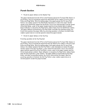
...the paper passes the Fin Input Path Sensor, the rotation speed of the Shift Roller toward the Exit Roller. After the punching operation is finished, the Exit Top Roller: Lower rotation speed returns to normal speed to reduce the paper transfer speed of the Exit Top Roller: Lower decreases... Roller and Regi Roller. Paper deflection is caused by the rotation of the Shift Roller decreases to restart the paper transfer. 1-28 Service Manual 4025-Finisher Punch Section • Route for paper delivery to the Top Tray Punching operation at the Top Tray Exit The paper transferred from the H-...
...the paper passes the Fin Input Path Sensor, the rotation speed of the Shift Roller toward the Exit Roller. After the punching operation is finished, the Exit Top Roller: Lower rotation speed returns to normal speed to reduce the paper transfer speed of the Exit Top Roller: Lower decreases... Roller and Regi Roller. Paper deflection is caused by the rotation of the Shift Roller decreases to restart the paper transfer. 1-28 Service Manual 4025-Finisher Punch Section • Route for paper delivery to the Top Tray Punching operation at the Top Tray Exit The paper transferred from the H-...

