Service Manual
Page 4
... Diagnostic aids 3-1 Understanding the printer control panel (models T650, T652, and T654 3-1 Accessing service menus (models T650, T652, and T654 3-2 Diagnostics mode (models T650, T652, and T654 3-3 Entering Diagnostics mode (models T650, T652, and T654 3-3 Available tests 3-3 Exiting Diagnostics mode (models T650, T652, and T654 3-5 REGISTRATION 3-5 Quick Test 3-6 PRINT TESTS 3-7 Input source tests 3-7 Print quality ... 3-12 Quick Test (duplex 3-12 Top Margin (duplex 3-13 Sensor Test (duplex 3-13 Motor Test (duplex 3-14 Duplex Feed 1 3-14 Duplex Feed 2 3-14 iv Service Manual
... Diagnostic aids 3-1 Understanding the printer control panel (models T650, T652, and T654 3-1 Accessing service menus (models T650, T652, and T654 3-2 Diagnostics mode (models T650, T652, and T654 3-3 Entering Diagnostics mode (models T650, T652, and T654 3-3 Available tests 3-3 Exiting Diagnostics mode (models T650, T652, and T654 3-5 REGISTRATION 3-5 Quick Test 3-6 PRINT TESTS 3-7 Input source tests 3-7 Print quality ... 3-12 Quick Test (duplex 3-12 Top Margin (duplex 3-13 Sensor Test (duplex 3-13 Motor Test (duplex 3-14 Duplex Feed 1 3-14 Duplex Feed 2 3-14 iv Service Manual

Service Manual
Page 6
4062-XXX Wiper Messages 3-28 Clear Custom Status 3-28 Best Speed 3-29 Exit Config Menu (models T650, T652, and T654 3-29 Understanding the printer control panel (model T656 3-29 Accessing service menus (model T656 3-30 Diagnostics Menu (model T656 3-31 Entering Diagnostics Menu (model T656 3-31 Available tests 3-31 Registration (printer 3-33 Quick... Transfer 3-46 Print Contrast 3-46 Charge Roll 3-46 Gap Adjust 3-47 Auto Dark Adjust 3-47 REPORTS 3-47 Menu Settings Page 3-47 EVENT LOG 3-47 vi Service Manual
4062-XXX Wiper Messages 3-28 Clear Custom Status 3-28 Best Speed 3-29 Exit Config Menu (models T650, T652, and T654 3-29 Understanding the printer control panel (model T656 3-29 Accessing service menus (model T656 3-30 Diagnostics Menu (model T656 3-31 Entering Diagnostics Menu (model T656 3-31 Available tests 3-31 Registration (printer 3-33 Quick... Transfer 3-46 Print Contrast 3-46 Charge Roll 3-46 Gap Adjust 3-47 Auto Dark Adjust 3-47 REPORTS 3-47 Menu Settings Page 3-47 EVENT LOG 3-47 vi Service Manual
Service Manual
Page 8
... empty 3-87 Sensor (media low 3-87 Sensor (pass-thru 3-87 Media transport path 3-89 Model T650 paper path, rolls, and sensors 3-89 Models T652 and T654 paper path, rolls, and sensors 3-90 Functions of main components 3-90 Media tray assembly 3-90 Rear media guide 3-90 Side guide 3-90 viii Service Manual
... empty 3-87 Sensor (media low 3-87 Sensor (pass-thru 3-87 Media transport path 3-89 Model T650 paper path, rolls, and sensors 3-89 Models T652 and T654 paper path, rolls, and sensors 3-90 Functions of main components 3-90 Media tray assembly 3-90 Rear media guide 3-90 Side guide 3-90 viii Service Manual
Service Manual
Page 10
... (T650, T652, T654 4-74 System card assembly removal (T650, T652, T654, T656 4-76 Transfer roll assembly removal (T650, T652, T654 4-78 Transfer roll bracket assembly, left removal (T650, T652, T654 4-79 Transfer roll bracket assembly, right removal (T650, T652, T654 4-80 Transfer deflector removal (T650, T652, T654 4-80 Tray roller catch assembly removal (T650, T652, T654 4-81 x Service Manual
... (T650, T652, T654 4-74 System card assembly removal (T650, T652, T654, T656 4-76 Transfer roll assembly removal (T650, T652, T654 4-78 Transfer roll bracket assembly, left removal (T650, T652, T654 4-79 Transfer roll bracket assembly, right removal (T650, T652, T654 4-80 Transfer deflector removal (T650, T652, T654 4-80 Tray roller catch assembly removal (T650, T652, T654 4-81 x Service Manual

Service Manual
Page 12
... 4-148 Lower interface cable assembly removal 4-156 Media size actuator removal 4-157 Media tray catch spring removal 4-158 Media out actuator removal (models T652 and T654 4-158 Media size actuator removal 4-159 Media tray catch spring removal 4-159 Media tray roller catch assembly removal 4-159 Output expander rear door assembly removal... removal 4-196 Tray roller catch assembly removal 4-197 Upper interface cable assembly removal 4-197 Connector locations and connections 5-1 Connections 5-1 Preventive maintenance 6-1 Safety inspection guide 6-1 xii Service Manual
... 4-148 Lower interface cable assembly removal 4-156 Media size actuator removal 4-157 Media tray catch spring removal 4-158 Media out actuator removal (models T652 and T654 4-158 Media size actuator removal 4-159 Media tray catch spring removal 4-159 Media tray roller catch assembly removal 4-159 Output expander rear door assembly removal... removal 4-196 Tray roller catch assembly removal 4-197 Upper interface cable assembly removal 4-197 Connector locations and connections 5-1 Connections 5-1 Preventive maintenance 6-1 Safety inspection guide 6-1 xii Service Manual

Service Manual
Page 14
4062-XXX xiv Service Manual
4062-XXX xiv Service Manual

Service Manual
Page 20
4062-XXX xx Service Manual
4062-XXX xx Service Manual

Service Manual
Page 24
...approach used to perform the task. Appendix A contains service tips and information. Unplug the product before you are working. 4062-XXX Preface This manual contains maintenance procedures for individual FRUs. Parts catalog contains illustrations and part numbers for service personnel. CAUTION This type of the product where you ...printer adjustments and removing and installing FRUs. 5. Conventions Note: A note provides additional information. Warning: A warning identifies something that might cause a servicer harm. xxiv Service Manual There are discussed. 2.
...approach used to perform the task. Appendix A contains service tips and information. Unplug the product before you are working. 4062-XXX Preface This manual contains maintenance procedures for individual FRUs. Parts catalog contains illustrations and part numbers for service personnel. CAUTION This type of the product where you ...printer adjustments and removing and installing FRUs. 5. Conventions Note: A note provides additional information. Warning: A warning identifies something that might cause a servicer harm. xxiv Service Manual There are discussed. 2.
Service Manual
Page 26
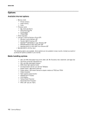
... Output expander - Bar Code and Forms - PRESCRIBE • Printer hard disk • Lexmark™ Internal Solutions Ports (ISP) - and 550-sheet paper trays of T652 and T654) - Envelope feeder (Not for options available in every country. Duplex option-550-sheet ...- StapleSmart™ Finisher - 5-bin Mailbox - Fonts • Firmware cards - Contact your country. RFID UHF (only for T654) 1-2 Service Manual Parallel 1284-B interface ISP - High-capacity output stacker - Vertical Kiosk Presenter - Printer memory - 4062-XXX Options Available internal options • ...
... Output expander - Bar Code and Forms - PRESCRIBE • Printer hard disk • Lexmark™ Internal Solutions Ports (ISP) - and 550-sheet paper trays of T652 and T654) - Envelope feeder (Not for options available in every country. Duplex option-550-sheet ...- StapleSmart™ Finisher - 5-bin Mailbox - Fonts • Firmware cards - Contact your country. RFID UHF (only for T654) 1-2 Service Manual Parallel 1284-B interface ISP - High-capacity output stacker - Vertical Kiosk Presenter - Printer memory - 4062-XXX Options Available internal options • ...

Service Manual
Page 28
4062-XXX Fully configured model The following illustration shows the fully configured printer model. For more than one input option. CAUTION: -TIPPING HAZARD: Floor-mounted configurations require additional furniture for stability. You must use either a printer stand or printer base if you are using a 2000-sheet tray, a duplex unit, and an input option, or more information, see www.lexmark.com/publications/furniture_safety. 1 2 3 4 5 6 7 8 9 1-4 Service Manual
4062-XXX Fully configured model The following illustration shows the fully configured printer model. For more than one input option. CAUTION: -TIPPING HAZARD: Floor-mounted configurations require additional furniture for stability. You must use either a printer stand or printer base if you are using a 2000-sheet tray, a duplex unit, and an input option, or more information, see www.lexmark.com/publications/furniture_safety. 1 2 3 4 5 6 7 8 9 1-4 Service Manual

Service Manual
Page 30
... 216 x 356 mm (8.5 x 14 in.) 98 x 191 mm (3.9 x 7.5 in.) 98 x 225 mm (3.9 x 8.9 in.) 105 x 241 mm (4.1 x 9.5 in.) 110 x 220 mm (4.3 x 8.7 in) Multipurpose feeder Duplex unit x x x x x x x x x x x x x x x x x x x x x x x x x x 1-6 Service Manual
... 216 x 356 mm (8.5 x 14 in.) 98 x 191 mm (3.9 x 7.5 in.) 98 x 225 mm (3.9 x 8.9 in.) 105 x 241 mm (4.1 x 9.5 in.) 110 x 220 mm (4.3 x 8.7 in) Multipurpose feeder Duplex unit x x x x x x x x x x x x x x x x x x x x x x x x x x 1-6 Service Manual

Service Manual
Page 32
...-blade 7/32 inch (5.5 mm) open-end wrench 7.0 mm nut driver Needle nose pliers Diagonal side cutters Spring hook Analog or digital multimeter Flash light (optional) 1-8 Service Manual Optional hardware Paper type Standard exit bin (350 or 550 sheets) Output Expander (550 sheets) or High Capacity Output stacker (1850 sheets) 5-Bin Mailbox (500...
...-blade 7/32 inch (5.5 mm) open-end wrench 7.0 mm nut driver Needle nose pliers Diagonal side cutters Spring hook Analog or digital multimeter Flash light (optional) 1-8 Service Manual Optional hardware Paper type Standard exit bin (350 or 550 sheets) Output Expander (550 sheets) or High Capacity Output stacker (1850 sheets) 5-Bin Mailbox (500...

Service Manual
Page 34
4062-XXX 1-10 Service Manual
4062-XXX 1-10 Service Manual
Service Manual
Page 35
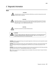
...-sensitive parts" on , never touch the conductive parts if not specifically required. Diagnostic information 2-1 Call your fingers are not contained in this service manual. Diagnostic information Start CAUTION: Unplug the power cord from their body, grounding their body while working. CAUTION: If the printer is kept on... page 4-1. WARNING: Servicers should wear a wrist band or the like to avoid burns by safely handling hot parts. Never touch the live even while the ...
...-sensitive parts" on , never touch the conductive parts if not specifically required. Diagnostic information 2-1 Call your fingers are not contained in this service manual. Diagnostic information Start CAUTION: Unplug the power cord from their body, grounding their body while working. CAUTION: If the printer is kept on... page 4-1. WARNING: Servicers should wear a wrist band or the like to avoid burns by safely handling hot parts. Never touch the live even while the ...

Service Manual
Page 36
The Lexmark splash screen appears with a progress bar in the power cord. • The printer is properly grounded. Release the buttons after 10 seconds. 2-2 Service Manual 4062 Confirm the installation status Be sure to the User's Guide for proper attachment and electrical connection. •... at a place subjected to extreme temperature, extreme humidity or rapid changes in temperature. • The printer is not installed close to water service, humidifier, heat generating unit, fire, in a very dusty place, or a place exposed to air flow from breakage, short-circuit, disconnected...
The Lexmark splash screen appears with a progress bar in the power cord. • The printer is properly grounded. Release the buttons after 10 seconds. 2-2 Service Manual 4062 Confirm the installation status Be sure to the User's Guide for proper attachment and electrical connection. •... at a place subjected to extreme temperature, extreme humidity or rapid changes in temperature. • The printer is not installed close to water service, humidifier, heat generating unit, fire, in a very dusty place, or a place exposed to air flow from breakage, short-circuit, disconnected...
Service Manual
Page 38
... or set to Auto, then exit the menus to enable Resource Save. Install additional printer memory. • Press until Busy/ Waiting appears. Reset Active Bin 2-4 Service Manual This message displays when the printer memory is disabled. • Press to disable Resource Save and continue printing. When Ready is available to complete the...
... or set to Auto, then exit the menus to enable Resource Save. Install additional printer memory. • Press until Busy/ Waiting appears. Reset Active Bin 2-4 Service Manual This message displays when the printer memory is disabled. • Press to disable Resource Save and continue printing. When Ready is available to complete the...
Service Manual
Page 40
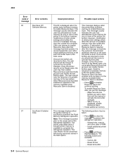
... Invalid protocol Valid but indicates bad RFID media. It is set to program, or the "Retry Count" has been exceeded. Replace the RFID UHF option. 2-6 Service Manual
... Invalid protocol Valid but indicates bad RFID media. It is set to program, or the "Retry Count" has been exceeded. Replace the RFID UHF option. 2-6 Service Manual
Service Manual
Page 42
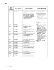
..., RFID interface card, RFID cable, and RFID option for correct installation. Install a new toner cartridge that differs from the below options. The flash is resolved. 2-8 Service Manual The following are not allowed until Busy/ Waiting appears. Cancel Job - Flash operations are available: - To clear this IR, the printer cartridge must be taken...
..., RFID interface card, RFID cable, and RFID option for correct installation. Install a new toner cartridge that differs from the below options. The flash is resolved. 2-8 Service Manual The following are not allowed until Busy/ Waiting appears. Cancel Job - Flash operations are available: - To clear this IR, the printer cartridge must be taken...

Service Manual
Page 44
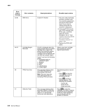
... are optional trays above the RFID option. The following actions may be taken: • Press to clear the message. Go to network service check. Turn off and unplug the printer. 2. Displayed when status is in the printer, and turn it on page 2-177. The printer... are entered or the printer is at least one input tray beneath the RFID option. 2. Remove the excess bins. 3. See "Network service check" on . 2-10 Service Manual Replace the RFID UHF option. 1. Once the error has been displayed for correct installation. The printer discards any data received on page ...
... are optional trays above the RFID option. The following actions may be taken: • Press to clear the message. Go to network service check. Turn off and unplug the printer. 2. Displayed when status is in the printer, and turn it on page 2-177. The printer... are entered or the printer is at least one input tray beneath the RFID option. 2. Remove the excess bins. 3. See "Network service check" on . 2-10 Service Manual Replace the RFID UHF option. 1. Once the error has been displayed for correct installation. The printer discards any data received on page ...

Service Manual
Page 46
... disk. Remove the incompatible trays. 3. Remove the incompatible output bin and press to clear the message. This error may occur at power on page 6-1. 2-12 Service Manual The disk is not shown. The Format Disk menu is marked defective and normal printer operations continue. It is installed. Remove the incompatible output option...
... disk. Remove the incompatible trays. 3. Remove the incompatible output bin and press to clear the message. This error may occur at power on page 6-1. 2-12 Service Manual The disk is not shown. The Format Disk menu is marked defective and normal printer operations continue. It is installed. Remove the incompatible output option...


