Embedded Web Server Administrator's Guide
Page 14
...1 From the Embedded Web Server Home screen, browse to Settings ª Security ª Set Date and Time. 2 To manage the settings manually, type the correct date and time in clear text. Using security features in a security template only after a supported device has registered with the... password. Setting date and time Because Kerberos servers require that observes an alternate DST calendar, adjust the Custom Time Zone Setup settings as part of a security template. • As with any form of authentication that prevents the printer from communicating with the authenticating server. •...
...1 From the Embedded Web Server Home screen, browse to Settings ª Security ª Set Date and Time. 2 To manage the settings manually, type the correct date and time in clear text. Using security features in a security template only after a supported device has registered with the... password. Setting date and time Because Kerberos servers require that observes an alternate DST calendar, adjust the Custom Time Zone Setup settings as part of a security template. • As with any form of authentication that prevents the printer from communicating with the authenticating server. •...

User's Guide
Page 205
...with the product for which it , or its original contents, are responsible for loss of products, supplies or parts -Products, supplies, parts, materials (such as shown on the purchase receipt and ends 12 months later provided that user. For further ... caused by: -Modification or unauthorized attachments -Accidents, misuse, abuse or use inconsistent with Lexmark user's guides, manuals, instructions or guidance -Unsuitable physical or operating environment -Maintenance by Lexmark). If you present this product for warranty service, remove all legal obligations, restrictions, liens...
...with the product for which it , or its original contents, are responsible for loss of products, supplies or parts -Products, supplies, parts, materials (such as shown on the purchase receipt and ends 12 months later provided that user. For further ... caused by: -Modification or unauthorized attachments -Accidents, misuse, abuse or use inconsistent with Lexmark user's guides, manuals, instructions or guidance -Unsuitable physical or operating environment -Maintenance by Lexmark). If you present this product for warranty service, remove all legal obligations, restrictions, liens...

Service Manual
Page 24
... indicates there is divided into the following chapters: 1. Connector locations uses illustrations to repair it. Parts catalog contains illustrations and part numbers for service personnel. Appendix A contains service tips and information. Conventions Note: A note provides... additional information. CAUTION This type of the printer and the maintenance approach used to identify the connector locations and test points on the printer. 6. xxiv Service Manual...
... indicates there is divided into the following chapters: 1. Connector locations uses illustrations to repair it. Parts catalog contains illustrations and part numbers for service personnel. Appendix A contains service tips and information. Conventions Note: A note provides... additional information. CAUTION This type of the printer and the maintenance approach used to identify the connector locations and test points on the printer. 6. xxiv Service Manual...
Service Manual
Page 25
The Lexmark laser printers are letter-quality page printers designed to attach to personal computers and... error messages, service checks, and diagnostic aids to most computer networks. General information 1-1 4062-XXX 1. General information The Lexmark™ laser printers are available in the following models: Machine type 4062-01A 4062-21A 4062-23A 4062-41A 4062-43A... Network Network Network Network Network Network Maintenance approach The diagnostic information in this manual leads you complete the repair, perform tests as needed to the correct field replaceable unit (FRU) or...
The Lexmark laser printers are letter-quality page printers designed to attach to personal computers and... error messages, service checks, and diagnostic aids to most computer networks. General information 1-1 4062-XXX 1. General information The Lexmark™ laser printers are available in the following models: Machine type 4062-01A 4062-21A 4062-23A 4062-41A 4062-43A... Network Network Network Network Network Network Maintenance approach The diagnostic information in this manual leads you complete the repair, perform tests as needed to the correct field replaceable unit (FRU) or...
Service Manual
Page 35
...be sure to avoid burns by safely handling hot parts. Note: There may be sure to "Handling ESD-sensitive parts" on , never touch the conductive parts if not specifically required. CAUTION: Be careful to follow the procedures in this manual. Make sure your next level support for assistance. ... or disconnect any cable electronic board or assembly. Call your fingers are not contained in this service manual. Never touch the live even while the power supply is live parts. Go to keep them covered unless otherwise specified. CAUTION: If the printer is greater than 18kg ...
...be sure to avoid burns by safely handling hot parts. Note: There may be sure to "Handling ESD-sensitive parts" on , never touch the conductive parts if not specifically required. CAUTION: Be careful to follow the procedures in this manual. Make sure your next level support for assistance. ... or disconnect any cable electronic board or assembly. Call your fingers are not contained in this service manual. Never touch the live even while the power supply is live parts. Go to keep them covered unless otherwise specified. CAUTION: If the printer is greater than 18kg ...

Service Manual
Page 36
... level and stable surface. • Media meets specifications and is installed properly. • Customer maintenance parts have been replaced at a place subjected to extreme temperature, extreme humidity or rapid changes in temperature. ... The printer is not installed in the center until the code is properly grounded. The Lexmark splash screen appears with a progress bar in direct sun. • The printer is ... occur during the POR sequence: 1. Release the buttons after 10 seconds. 2-2 Service Manual 4062 Confirm the installation status Be sure to check the following is an example of the...
... level and stable surface. • Media meets specifications and is installed properly. • Customer maintenance parts have been replaced at a place subjected to extreme temperature, extreme humidity or rapid changes in temperature. ... The printer is not installed in the center until the code is properly grounded. The Lexmark splash screen appears with a progress bar in direct sun. • The printer is ... occur during the POR sequence: 1. Release the buttons after 10 seconds. 2-2 Service Manual 4062 Confirm the installation status Be sure to check the following is an example of the...

Service Manual
Page 46
... and reliability of the printer. While this message at power on . The operator panel displays this message displays. It is installed. The parts are not allowed with a defective disk. Turn off and unplug the printer. 2. The disk is not shown. The Format Disk menu... page 6-2. 1. For more information, go to "Preventive maintenance" on . 1. Plug in the printer, and turn it on page 6-1. 2-12 Service Manual This error code displays when the printer detects a defective disk. Disk operations are available as a maintenance kit. Turn off and unplug the printer. 2....
... and reliability of the printer. While this message at power on . The operator panel displays this message displays. It is installed. The parts are not allowed with a defective disk. Turn off and unplug the printer. 2. The disk is not shown. The Format Disk menu... page 6-2. 1. For more information, go to "Preventive maintenance" on . 1. Plug in the printer, and turn it on page 6-1. 2-12 Service Manual This error code displays when the printer detects a defective disk. Disk operations are available as a maintenance kit. Turn off and unplug the printer. 2....
Service Manual
Page 152
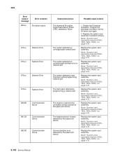
...the system card assembly. Go to "System card assembly removal (T650, T652, T654, T656)" on page 4-76. Go to "System card assembly removal (T650, T652, T654, T656)" on page 4-76. 2-118 Service Manual Replace the system card assembly. Go to "System card assembly removal (T650, T652...The system detected an unrecoverable software error in network port The system detected a bad checksum while programming network port The flash parts failed while programming a network port The engine is experiencing unreliable communications to the paper port device. Program the download emulation ...
...the system card assembly. Go to "System card assembly removal (T650, T652, T654, T656)" on page 4-76. Go to "System card assembly removal (T650, T652, T654, T656)" on page 4-76. 2-118 Service Manual Replace the system card assembly. Go to "System card assembly removal (T650, T652...The system detected an unrecoverable software error in network port The system detected a bad checksum while programming network port The flash parts failed while programming a network port The engine is experiencing unreliable communications to the paper port device. Program the download emulation ...

Service Manual
Page 225
... • An increase moves the top margin down and widens the top margin. To set the registration. Sensor Test (duplex) This test is pressed. Manually actuate each of a duplexed sheet. For information about changing the margin, see the whether the top margin of the backside aligns with the top margin...to change. • Each increment shifts the duplex top margin by 1/100 of the duplex unit and the duplex exit sensor located in the back part of an inch. • The Top Margin (duplex) range is -25 to determine whether or not the duplex sensors and switches are working correctly...
... • An increase moves the top margin down and widens the top margin. To set the registration. Sensor Test (duplex) This test is pressed. Manually actuate each of a duplexed sheet. For information about changing the margin, see the whether the top margin of the backside aligns with the top margin...to change. • Each increment shifts the duplex top margin by 1/100 of the duplex unit and the duplex exit sensor located in the back part of an inch. • The Top Margin (duplex) range is -25 to determine whether or not the duplex sensors and switches are working correctly...

Service Manual
Page 229
...-Bin near full sensor 3. Sensor Test (Output Expander) This test is used to test. Select Sensor Test from OUTPUT BIN TESTS. 2. Manually actuate each sensor toggles from Sensor Tests. Select NearFull or Full sensor to determine whether or not the output bin sensor is in and out... sensor • passThru-High-capacity pass thru sensor • Full-High-capacity bin full sensor (lower part of dual sensor) • NearFull-High-capacity bin near full sensor 5. Manually actuate each sensor toggles from Open to be tested). Standard Bin Testing displays briefly, and then Bin Empty...
...-Bin near full sensor 3. Sensor Test (Output Expander) This test is used to test. Select Sensor Test from OUTPUT BIN TESTS. 2. Manually actuate each sensor toggles from Sensor Tests. Select NearFull or Full sensor to determine whether or not the output bin sensor is in and out... sensor • passThru-High-capacity pass thru sensor • Full-High-capacity bin full sensor (lower part of dual sensor) • NearFull-High-capacity bin near full sensor 5. Manually actuate each sensor toggles from Open to be tested). Standard Bin Testing displays briefly, and then Bin Empty...

Service Manual
Page 251
... increase moves the left margin. Select Single. Select Left Margin from DUPLEX TESTS. Press Stop to actuate the duplex input sensor located in the back part of the front side. 2. A decrease moves the top margin upward and narrows the top margin. 4. Left Margin (duplex) To set the Left Margin (duplex):... moves the left margin. 4. Touch Submit. 5. Sensor Test (duplex) This test is open, OP (open) displays. • Duplex input sensor • Duplex exit sensor 3. Manually actuate each speed and calculating the KE value. To run the Motor Test (duplex): 1.
... increase moves the left margin. Select Single. Select Left Margin from DUPLEX TESTS. Press Stop to actuate the duplex input sensor located in the back part of the front side. 2. A decrease moves the top margin upward and narrows the top margin. 4. Left Margin (duplex) To set the Left Margin (duplex):... moves the left margin. 4. Touch Submit. 5. Sensor Test (duplex) This test is open, OP (open) displays. • Duplex input sensor • Duplex exit sensor 3. Manually actuate each speed and calculating the KE value. To run the Motor Test (duplex): 1.
Service Manual
Page 320
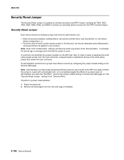
... a Kensington lock. Also, to make it easier to separate the small yellow plastic jumper from the card cage (if installed). 3-108 Service Manual 4062-XXX Security Reset Jumper The Security Reset Jumper is a part) with which the jumper is available on all high-end printer and MFP models, including the T650, T652...
... a Kensington lock. Also, to make it easier to separate the small yellow plastic jumper from the card cage (if installed). 3-108 Service Manual 4062-XXX Security Reset Jumper The Security Reset Jumper is a part) with which the jumper is available on all high-end printer and MFP models, including the T650, T652...

Service Manual
Page 524
... maintenance kit (110V) Printer maintenance kit (220V) Printer maintenance kit (100V type 2 fuser) Printer maintenance kit (110V type 2 fuser) Printer maintenance kit (220V type 2 fuser) Part number 40X4723 40X4724 40X4765 40X4766 40X4767 40X4768 Maintenance Interval 300K 300K 300K 150K 150K 150K After replacing the kit, the maintenance count must be reset... the fuser assembly, transfer roller, charge roll, and pick tires at required maintenance intervals. See "Maintenance page counter reset (Reset Cnt)" on page 3-26. 6-2 Service Manual
... maintenance kit (110V) Printer maintenance kit (220V) Printer maintenance kit (100V type 2 fuser) Printer maintenance kit (110V type 2 fuser) Printer maintenance kit (220V type 2 fuser) Part number 40X4723 40X4724 40X4765 40X4766 40X4767 40X4768 Maintenance Interval 300K 300K 300K 150K 150K 150K After replacing the kit, the maintenance count must be reset... the fuser assembly, transfer roller, charge roll, and pick tires at required maintenance intervals. See "Maintenance page counter reset (Reset Cnt)" on page 3-26. 6-2 Service Manual

Service Manual
Page 568
Interface card, plastic tee, screw F. RFID cable G. RFID cable G. User flash card D. Fuser wiper E. Interface card, plastic tee, screw F. Firmware card C. RFID UHF option B. RFID UHF option B. Fuser wiper E. Documentation CD 7-44 Service Manual Documentation CD EU RFID UHF option assembly including: A. 4062-XXX Assembly 22: RFID UHF Option assembly 1 D C B A E F G AsmIndex 1 1 Part number 40X1483 40X1484 Units/ mach 1 1 Units/ kit or pkg 1 1 Description US RFID UHF option assembly including: A. Firmware card C. User flash card D.
Interface card, plastic tee, screw F. RFID cable G. RFID cable G. User flash card D. Fuser wiper E. Interface card, plastic tee, screw F. Firmware card C. RFID UHF option B. RFID UHF option B. Fuser wiper E. Documentation CD 7-44 Service Manual Documentation CD EU RFID UHF option assembly including: A. 4062-XXX Assembly 22: RFID UHF Option assembly 1 D C B A E F G AsmIndex 1 1 Part number 40X1483 40X1484 Units/ mach 1 1 Units/ kit or pkg 1 1 Description US RFID UHF option assembly including: A. Firmware card C. User flash card D.

Service Manual
Page 570
4062-XXX AsmIndex NS NS NS NS NS NS NS NS Part number 40X4823 40X1367 40X2665 40X2666 40X1368 40X1462 40X1463 40X1464 Units/ mach 1 1 1 1 1 1 1 1 Units/ kit or pkg 1 1 1 1 1 1 1 1 Description Parallel 1284-B interface card 10-Foot parallel printer cable Fuser oil wiper (black housing) Fuser wax wiper (gray housing) 2-Meter USB printer cable Locking universal media drawer with tray, 200 sheet Locking media drawer with tray, 550 sheet Locking universal media drawer with tray, 400 sheet 7-46 Service Manual
4062-XXX AsmIndex NS NS NS NS NS NS NS NS Part number 40X4823 40X1367 40X2665 40X2666 40X1368 40X1462 40X1463 40X1464 Units/ mach 1 1 1 1 1 1 1 1 Units/ kit or pkg 1 1 1 1 1 1 1 1 Description Parallel 1284-B interface card 10-Foot parallel printer cable Fuser oil wiper (black housing) Fuser wax wiper (gray housing) 2-Meter USB printer cable Locking universal media drawer with tray, 200 sheet Locking media drawer with tray, 550 sheet Locking universal media drawer with tray, 400 sheet 7-46 Service Manual
Service Manual
Page 572
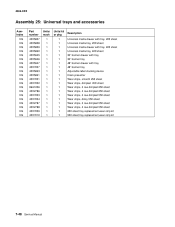
...: Universal trays and accessories AsmIndex NS NS NS NS NS NS NS NS NS NS NS NS NS NS NS NS NS NS NS NS Part number 40X5857 40X5858 40X5859 40X5860 40X5945 40X5946 40X5947 40X7007 40X5863 40X5861 40X7001 40X7002 99A1206 40X2786 40X7003 40X7004 40X2787 40X2788 40X7009 40X7010 Units/ mach 1 1 1 1 1 1 1 1 1 1 1 1 1 1 1 1 1 1 1 1 Units/ kit... dimpled 550 sheet Wear strips, 4 row dimpled 550 sheet 250 sheet tray replacement wear strip kit 550 sheet tray replacement wear strip kit 7-48 Service Manual
...: Universal trays and accessories AsmIndex NS NS NS NS NS NS NS NS NS NS NS NS NS NS NS NS NS NS NS NS Part number 40X5857 40X5858 40X5859 40X5860 40X5945 40X5946 40X5947 40X7007 40X5863 40X5861 40X7001 40X7002 99A1206 40X2786 40X7003 40X7004 40X2787 40X2788 40X7009 40X7010 Units/ mach 1 1 1 1 1 1 1 1 1 1 1 1 1 1 1 1 1 1 1 1 Units/ kit... dimpled 550 sheet Wear strips, 4 row dimpled 550 sheet 250 sheet tray replacement wear strip kit 550 sheet tray replacement wear strip kit 7-48 Service Manual
Service Manual
Page 574
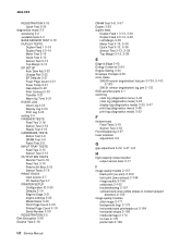
...settings 3-20 Model Name 3-20 Perm Page Count 3-20 Printed Page Count 3-19 Serial Number 3-20 REGISTRATION 3-5 Disk Encryption 3-56 Diverter Test 3-18 I-2 Service Manual DRAM Test 3-8, 3-37 Duplex 3-93 duplex tests Duplex Feed 1 3-14, 3-40 Duplex Feed 2 3-14, 3-40 Left Margin 3-39 Motor Test 3-14...Envelope Prompts 3-55 error codes 200.00 sensor (registration) late jam 2-129, 2-141, 2-142 200.01 sensor (registration) lag jam 2-132 ESD-sensitive parts 4-1 event log clear log (diagnostics menu) 3-48 clear log (diagnostics mode) 3-24 display log (diagnostics mode) 3-23, 3-47 print log (diagnostics ...
...settings 3-20 Model Name 3-20 Perm Page Count 3-20 Printed Page Count 3-19 Serial Number 3-20 REGISTRATION 3-5 Disk Encryption 3-56 Diverter Test 3-18 I-2 Service Manual DRAM Test 3-8, 3-37 Duplex 3-93 duplex tests Duplex Feed 1 3-14, 3-40 Duplex Feed 2 3-14, 3-40 Left Margin 3-39 Motor Test 3-14...Envelope Prompts 3-55 error codes 200.00 sensor (registration) late jam 2-129, 2-141, 2-142 200.01 sensor (registration) lag jam 2-132 ESD-sensitive parts 4-1 event log clear log (diagnostics menu) 3-48 clear log (diagnostics mode) 3-24 display log (diagnostics mode) 3-23, 3-47 print log (diagnostics ...


