Service Manual
Page 6
...process 3-33 Electrophotographic process basics 3-33 Step 1: Charge 3-34 Step 2: Expose 3-35 Step 3: Develop 3-36 Step 4a: First transfer 3-37 Step 4b: Second transfer 3-38 Step 5: Fuse 3-39 Step 6: Clean/erase 3-40 Paper path, transport components 3-42 Paper path Information 3-42 Transport ...Fuser drive motor assembly removal 4-29 Fuser exit sensor removal 4-30 High-voltage power supply (HVPS) assembly removal 4-31 Image transfer unit (ITU) removal 4-33 Imaging unit (IU) removal 4-35 Low-voltage power supply (LVPS) assembly removal 4-37 Lower frame removal, right and left 4-39...
...process 3-33 Electrophotographic process basics 3-33 Step 1: Charge 3-34 Step 2: Expose 3-35 Step 3: Develop 3-36 Step 4a: First transfer 3-37 Step 4b: Second transfer 3-38 Step 5: Fuse 3-39 Step 6: Clean/erase 3-40 Paper path, transport components 3-42 Paper path Information 3-42 Transport ...Fuser drive motor assembly removal 4-29 Fuser exit sensor removal 4-30 High-voltage power supply (HVPS) assembly removal 4-31 Image transfer unit (ITU) removal 4-33 Imaging unit (IU) removal 4-35 Low-voltage power supply (LVPS) assembly removal 4-37 Lower frame removal, right and left 4-39...
Service Manual
Page 33
... Black Only Retract Cyan Dual Inline Memory Module Dynamic Random Access Memory Electrically Erasable Programmable Read-Only Memory ElectroPhotographic Electrostatic Discharge Field Replaceable Unit Gigabyte High-Voltage Power Supply Image Transfer Unit Imaging Unit Japanese Industry Standard Black Light Amplification by Stimulated Emission of Radiation Liquid Crystal Display Light-Emitting Diode Low-Voltage Power Supply Magenta...
... Black Only Retract Cyan Dual Inline Memory Module Dynamic Random Access Memory Electrically Erasable Programmable Read-Only Memory ElectroPhotographic Electrostatic Discharge Field Replaceable Unit Gigabyte High-Voltage Power Supply Image Transfer Unit Imaging Unit Japanese Industry Standard Black Light Amplification by Stimulated Emission of Radiation Liquid Crystal Display Light-Emitting Diode Low-Voltage Power Supply Magenta...
Service Manual
Page 77
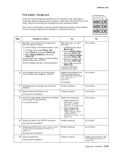
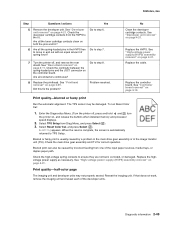
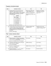
...Lexmark toner cartridges may also cause background problems. Some problems occur by using rough paper or incorrectly setting the operator panel settings to rough texture when the texture is possible a new imaging unit was installed, but the counter was not reset. To view the status of the photoconductor units...voltage power supply (HVPS) assembly removal" on page 4-31. Replace the failing part: • Image transfer unit (ITU). Go to step 4. 4 Replace the photoconductor unit. Print quality-background Service tip: Some background problems can be caused by running a large amount of...
...Lexmark toner cartridges may also cause background problems. Some problems occur by using rough paper or incorrectly setting the operator panel settings to rough texture when the texture is possible a new imaging unit was installed, but the counter was not reset. To view the status of the photoconductor units...voltage power supply (HVPS) assembly removal" on page 4-31. Replace the failing part: • Image transfer unit (ITU). Go to step 4. 4 Replace the photoconductor unit. Print quality-background Service tip: Some background problems can be caused by running a large amount of...
Service Manual
Page 79
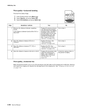
...IU? 6 Are all the spring-loaded pins in the HVPS free to the IU. Select TPS Setup from the HVPS to move in the image transfer unit (ITU). Blurred or fuzzy print is automatically returned to ensure they are not bent, corroded, or damaged. See "High-voltage power supply (.... Select Reset Color Cal, and press Select ( ). Check the high-voltage spring contacts to TPS Setup. Reseat the imaging unit. If that does not work, remove the imaging unit and reseat each of spring force? Print quality-blurred or fuzzy print Run the automatic alignment. Diagnostic information 2-45 Check ...
...IU? 6 Are all the spring-loaded pins in the HVPS free to the IU. Select TPS Setup from the HVPS to move in the image transfer unit (ITU). Blurred or fuzzy print is automatically returned to ensure they are not bent, corroded, or damaged. See "High-voltage power supply (.... Select Reset Color Cal, and press Select ( ). Check the high-voltage spring contacts to TPS Setup. Reseat the imaging unit. If that does not work, remove the imaging unit and reseat each of spring force? Print quality-blurred or fuzzy print Run the automatic alignment. Diagnostic information 2-45 Check ...
Service Manual
Page 80
...? See "Image transfer unit (ITU) removal" on page 4-35. 2-46 Service Manual Go to step 2. 2 Does the distance measure 95 mm or 108 mm? Check the various rollers in the printer for debris. See "Imaging unit (IU) removal" on page 4-33. See "Imaging unit (IU) ..., and press Select ( ). 3. Remove the imaging unit and remove the original developer units, and then put them back into the new photoconductor unit, and reinstall the imaging unit. Go to step 4. See "Developer unit removal" on page 4-21. Remove and inspect the imaging unit. At the Ready prompt, press Menu ( ...
...? See "Image transfer unit (ITU) removal" on page 4-35. 2-46 Service Manual Go to step 2. 2 Does the distance measure 95 mm or 108 mm? Check the various rollers in the printer for debris. See "Imaging unit (IU) removal" on page 4-33. See "Imaging unit (IU) ..., and press Select ( ). 3. Remove the imaging unit and remove the original developer units, and then put them back into the new photoconductor unit, and reinstall the imaging unit. Go to step 4. See "Developer unit removal" on page 4-21. Remove and inspect the imaging unit. At the Ready prompt, press Menu ( ...
Service Manual
Page 82
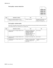
... loose or foreign material on page 4-33. Print quality-random marks Service tip: The primary cause of support. 2-48 Service Manual See "Image transfer unit (ITU) removal" on the transfer belt? See "Developer unit removal" on page 4-21. 5025-2xx, 4xx Print quality-narrow vertical line ABCDE ABCDE ABCDE Step Questions / actions 1 Replace the photoconductor...
... loose or foreign material on page 4-33. Print quality-random marks Service tip: The primary cause of support. 2-48 Service Manual See "Image transfer unit (ITU) removal" on the transfer belt? See "Developer unit removal" on page 4-21. 5025-2xx, 4xx Print quality-narrow vertical line ABCDE ABCDE ABCDE Step Questions / actions 1 Replace the photoconductor...
Service Manual
Page 84
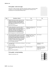
... test the printhead for removal procedures. Replace the printhead. See "Printhead removal" on page 4-19. Problem resolved. Remove the imaging unit and remove the developers. Ensure the contact springs are properly mounted and that runs through the left printer frame. Are the spring...page have a white vertical band? 3 Check the high-voltage contact from discharging the photoconductors. Replace the transfer contact assembly. See "Toner cartridge contacts" on page 4-31. See "Imaging unit (IU) removal". Print a Quality Test Page. Go to step 4. Is there continuity? 5 Replace the...
... test the printhead for removal procedures. Replace the printhead. See "Printhead removal" on page 4-19. Problem resolved. Remove the imaging unit and remove the developers. Ensure the contact springs are properly mounted and that runs through the left printer frame. Are the spring...page have a white vertical band? 3 Check the high-voltage contact from discharging the photoconductors. Replace the transfer contact assembly. See "Toner cartridge contacts" on page 4-31. See "Imaging unit (IU) removal". Print a Quality Test Page. Go to step 4. Is there continuity? 5 Replace the...
Service Manual
Page 87
...remain on the display? 2 Check the vertical wall (or web) at the left rear of the tray for a dislodged sensor. Problem resolved. See "Image transfer unit (ITU) removal" on page 4-19. 2 Turn the printer off , and remove the rear shield. Replace the tray. Diagnostic information 2-53 Yes ... 2. If the problem persists, go to step 2. Tray 1 sensor service check Step Questions / actions 1 When the printer is pulled out? See "Image transfer unit (ITU) removal" on page 4-11. Turn the printer on, and check the cable at JHVPS1 connector on page 4-31. See "High-voltage power ...
...remain on the display? 2 Check the vertical wall (or web) at the left rear of the tray for a dislodged sensor. Problem resolved. See "Image transfer unit (ITU) removal" on page 4-19. 2 Turn the printer off , and remove the rear shield. Replace the tray. Diagnostic information 2-53 Yes ... 2. If the problem persists, go to step 2. Tray 1 sensor service check Step Questions / actions 1 When the printer is pulled out? See "Image transfer unit (ITU) removal" on page 4-11. Turn the printer on, and check the cable at JHVPS1 connector on page 4-31. See "High-voltage power ...
Service Manual
Page 123
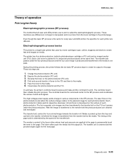
... to the media. Even though the basic EP process is called a photodeveloper cartridge or PC unit) and an image transfer unit (ITU). Each photoconductor rotates past its output to the printed page. The transfer belt passes under the photoconductors. In summary, the printer's controller board receives print data and the command to the media 6. Expose...
... to the media. Even though the basic EP process is called a photodeveloper cartridge or PC unit) and an image transfer unit (ITU). Each photoconductor rotates past its output to the printed page. The transfer belt passes under the photoconductors. In summary, the printer's controller board receives print data and the command to the media 6. Expose...
Service Manual
Page 128
... be due to a "contact" transfer instead of a "charge" transfer. The paper passes between the transfer belt and transfer roll when the image on the transfer belt reaches the transfer roll, the negatively charged toner clings to the media and the entire image is transferred from the transfer unit; Once the image on the belt reaches the second transfer area. Based on it, the...
... be due to a "contact" transfer instead of a "charge" transfer. The paper passes between the transfer belt and transfer roll when the image on the transfer belt reaches the transfer roll, the negatively charged toner clings to the media and the entire image is transferred from the transfer unit; Once the image on the belt reaches the second transfer area. Based on it, the...

Service Manual
Page 130
5025-2xx, 4xx Step 6: Clean/erase There are two main cleaning processes that is cleaned by the cleaning blade (G). After the toner is moved to the cleaning blade, the toner is moved from the cleaning blade to the page, the transfer belt rotates around and is printed. This occurs for every page that take place during the EP process. Transfer unit clean Once the toner image on the transfer belt has been transferred to the waste toner area using an auger system. 3-40 Service Manual One process cleans the transfer belt and the other cleans the photoconductors.
5025-2xx, 4xx Step 6: Clean/erase There are two main cleaning processes that is cleaned by the cleaning blade (G). After the toner is moved to the cleaning blade, the toner is moved from the cleaning blade to the page, the transfer belt rotates around and is printed. This occurs for every page that take place during the EP process. Transfer unit clean Once the toner image on the transfer belt has been transferred to the waste toner area using an auger system. 3-40 Service Manual One process cleans the transfer belt and the other cleans the photoconductors.

Service Manual
Page 134
Note: While the sheet is being transported through the duplex unit. The paper travels to the ITU (C), and the second image is transferred to prepare the fuser for the page traveling through the front door and paper tray, it is the only piece of the media. The reversed ... being processed. When the S2 signal is detected, the speed of the image on the second side of a sheet of media into the duplex paper path. Once the image is transferred, the media travels to accommodate the speed of the transfer belt, ensuring the proper registration of the pick motor is adjusted to the...
Note: While the sheet is being transported through the duplex unit. The paper travels to the ITU (C), and the second image is transferred to prepare the fuser for the page traveling through the front door and paper tray, it is the only piece of the media. The reversed ... being processed. When the S2 signal is detected, the speed of the image on the second side of a sheet of media into the duplex paper path. Once the image is transferred, the media travels to accommodate the speed of the transfer belt, ensuring the proper registration of the pick motor is adjusted to the...
Service Manual
Page 171
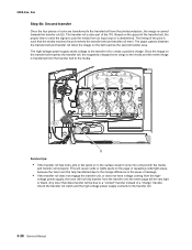
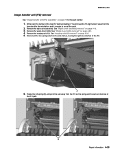
... new ITU before installing it is easier to the ITU. 6. Remove the right cover assembly. Remove the waste toner bottle. See "Imaging unit (IU) removal" on page 4-60. 4. You will need the 16-digit numeric value from the side frames, leaving the right ...of the ITU path. Disconnect the two springs (A) from the barcode after the installation, and it . Remove the imaging unit (IU). Repair information 4-33 See "Right cover assembly removal" on page 7-5 for the part number. 1. 5025-2xx, 4xx Image transfer unit (ITU) removal See "Image transfer unit (ITU) assembly" on page 4-10. 3.
... new ITU before installing it is easier to the ITU. 6. Remove the right cover assembly. Remove the waste toner bottle. See "Imaging unit (IU) removal" on page 4-60. 4. You will need the 16-digit numeric value from the side frames, leaving the right ...of the ITU path. Disconnect the two springs (A) from the barcode after the installation, and it . Remove the imaging unit (IU). Repair information 4-33 See "Right cover assembly removal" on page 7-5 for the part number. 1. 5025-2xx, 4xx Image transfer unit (ITU) removal See "Image transfer unit (ITU) assembly" on page 4-10. 3.
Service Manual
Page 191
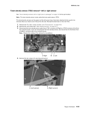
... "Rear shield removal" on the left side. Remove the ITU. Repair information 4-53 Note: Observe the routing of the cable(s) for the part number. See "Image transfer unit (ITU) removal" on the controller board. If you install a new TDS on page 4-11. 3. Remove the two screws (C) securing each sensor. Reinstall the thermistor on...
... "Rear shield removal" on the left side. Remove the ITU. Repair information 4-53 Note: Observe the routing of the cable(s) for the part number. See "Image transfer unit (ITU) removal" on the controller board. If you install a new TDS on page 4-11. 3. Remove the two screws (C) securing each sensor. Reinstall the thermistor on...

Service Manual
Page 223
...2-1 2 3 4 5 6 7 8 8 8 9 Part number 40X5411 40X5415 40X5422 40X5424 40X5403 40X5410 40X5412 40X5437 40X5438 40X5439 40X5433 Units/ mach 1 1 1 1 1 1 1 1 1 1 1 Units/ FRU 1 1 1 1 1 1 1 1 1 1 1 Description Printhead Fuser drive motor assembly Lower left frame and lower ...8226; M3.5 X 5 Flat Head Plastite (1) • METAL ROLN M3.5 8L (2) • PLAST ROLN 2.9 8L (2) • PLAST ROLN 3.5 6L (4) Image transfer unit (ITU) assembly Autocompensator mechanism (ACM)-standard tray Main drive gear assembly, with motors Fuser assembly, 115 V Fuser assembly, 230 V Fuser assembly 100 V Exit deflector...
...2-1 2 3 4 5 6 7 8 8 8 9 Part number 40X5411 40X5415 40X5422 40X5424 40X5403 40X5410 40X5412 40X5437 40X5438 40X5439 40X5433 Units/ mach 1 1 1 1 1 1 1 1 1 1 1 Units/ FRU 1 1 1 1 1 1 1 1 1 1 1 Description Printhead Fuser drive motor assembly Lower left frame and lower ...8226; M3.5 X 5 Flat Head Plastite (1) • METAL ROLN M3.5 8L (2) • PLAST ROLN 2.9 8L (2) • PLAST ROLN 3.5 6L (4) Image transfer unit (ITU) assembly Autocompensator mechanism (ACM)-standard tray Main drive gear assembly, with motors Fuser assembly, 115 V Fuser assembly, 230 V Fuser assembly 100 V Exit deflector...
Service Manual
Page 230
...14 EP Setup DC Charge Adjust 3-20 Dev Bias Adj 3-20 EP Defaults 3-19 Fuser Temp 3-19 Transfer Adjust 3-20 Event Log Clear Log 3-22 Display Log 3-21 Print Log 3-22 exit diagnostics 3-23 Hardware... 4-21 Left Margin 3-14 models 1-8 Quick Test 3-13 theory 3-44 Top Margin 3-14 duplex sensor locations 5-1 duplex unit parts catalog 7-2 E electrophotographic process (EP process) 3-33 Energy Conserve 3-26 engine setting 3-18 error codes 1xx service ...H high-voltage power supply (HVPS) connections 5-10 parts catalog 7-6 removal 4-31 I image transfer unit (ITU) ITU Barcode 3-19 parts catalog 7-4 removal 4-33
...14 EP Setup DC Charge Adjust 3-20 Dev Bias Adj 3-20 EP Defaults 3-19 Fuser Temp 3-19 Transfer Adjust 3-20 Event Log Clear Log 3-22 Display Log 3-21 Print Log 3-22 exit diagnostics 3-23 Hardware... 4-21 Left Margin 3-14 models 1-8 Quick Test 3-13 theory 3-44 Top Margin 3-14 duplex sensor locations 5-1 duplex unit parts catalog 7-2 E electrophotographic process (EP process) 3-33 Energy Conserve 3-26 engine setting 3-18 error codes 1xx service ...H high-voltage power supply (HVPS) connections 5-10 parts catalog 7-6 removal 4-31 I image transfer unit (ITU) ITU Barcode 3-19 parts catalog 7-4 removal 4-33
Service Manual
Page 232
...cover 4-10 top cover assembly 4-12 developer unit 4-21 duplex sensor 4-21 exit deflector 4-24 fuser assembly 4-26 fuser drive motor assembly 4-29 fuser exit sensor 4-30 getting started 4-2 high-voltage power supply (HVPS) 4-31 image transfer unit (ITU) 4-33 imaging unit (IU) 4-35 left lower frame 4-39... low-voltage power supply (LVPS) 4-37 main drive gear assembly 4-45 photoconductor unit 4-35 pick tires, 250-sheet media tray 4-48 printhead 4-49 right ...
...cover 4-10 top cover assembly 4-12 developer unit 4-21 duplex sensor 4-21 exit deflector 4-24 fuser assembly 4-26 fuser drive motor assembly 4-29 fuser exit sensor 4-30 getting started 4-2 high-voltage power supply (HVPS) 4-31 image transfer unit (ITU) 4-33 imaging unit (IU) 4-35 left lower frame 4-39... low-voltage power supply (LVPS) 4-37 main drive gear assembly 4-45 photoconductor unit 4-35 pick tires, 250-sheet media tray 4-48 printhead 4-49 right ...
Service Manual
Page 235
... and USB port cable)-C543dn, C544dn, C544n (40X5430 7-3 Fuser assembly 100 V (40X5439 7-5 Fuser assembly, 115 V (40X5437 7-5 Fuser assembly, 230 V (40X5438 7-5 Fuser drive motor assembly (40X5415 7-5 Fuser exit sensor (40X5413 7-7 High-voltage power supply (40X5405 7-7 Image transfer unit (ITU) assembly (40X5403... panel and display assembly (40X5431 7-3 Operator panel bezel and name plates (40X5432 7-3 Optional 550-sheet duo drawer with 100-sheet MPF unit (complete) (40X5434 7-9 Photo sensor (one per package) (40X5426 7-7 Pick tires (40X5168 7-9 Power cord, 1.8M (straight)-Australia ...
... and USB port cable)-C543dn, C544dn, C544n (40X5430 7-3 Fuser assembly 100 V (40X5439 7-5 Fuser assembly, 115 V (40X5437 7-5 Fuser assembly, 230 V (40X5438 7-5 Fuser drive motor assembly (40X5415 7-5 Fuser exit sensor (40X5413 7-7 High-voltage power supply (40X5405 7-7 Image transfer unit (ITU) assembly (40X5403... panel and display assembly (40X5431 7-3 Operator panel bezel and name plates (40X5432 7-3 Optional 550-sheet duo drawer with 100-sheet MPF unit (complete) (40X5434 7-9 Photo sensor (one per package) (40X5426 7-7 Pick tires (40X5168 7-9 Power cord, 1.8M (straight)-Australia ...

