User Manual
Page 6
... toner bottle ...114 Replacing a black imaging kit ...117 Replacing a black and color imaging kit ...123 Replacing a toner cartridge...128 Replacing a developer unit ...130 Cleaning the exterior of the printer...135 Recycling Lexmark products...136 Moving the printer...136 Before moving the printer...136 Moving the printer to another location...136 Shipping the printer...
... toner bottle ...114 Replacing a black imaging kit ...117 Replacing a black and color imaging kit ...123 Replacing a toner cartridge...128 Replacing a developer unit ...130 Cleaning the exterior of the printer...135 Recycling Lexmark products...136 Moving the printer...136 Before moving the printer...136 Moving the printer to another location...136 Shipping the printer...

User Manual
Page 120
Maintaining the printer 120 8 Remove the yellow, cyan, and magenta developer units. 9 Unpack the replacement black imaging kit. Leave the packaging on the black developer unit. 10 Gently shake the black developer unit side to side. 11 Remove the packaging from the black developer unit. 12 Insert the black developer unit.
Maintaining the printer 120 8 Remove the yellow, cyan, and magenta developer units. 9 Unpack the replacement black imaging kit. Leave the packaging on the black developer unit. 10 Gently shake the black developer unit side to side. 11 Remove the packaging from the black developer unit. 12 Insert the black developer unit.

User Manual
Page 121
13 Replace the yellow, cyan, and magenta developer units. For more information, see Recycling Lexmark Products. 15 Align and insert the imaging kit. 16 Rotate the blue levers down until the imaging kit drops into a matching color slot. 14 Place the used black imaging kit in the enclosed package. Maintaining the printer 121 Note: Make sure each developer unit is inserted into place.
13 Replace the yellow, cyan, and magenta developer units. For more information, see Recycling Lexmark Products. 15 Align and insert the imaging kit. 16 Rotate the blue levers down until the imaging kit drops into a matching color slot. 14 Place the used black imaging kit in the enclosed package. Maintaining the printer 121 Note: Make sure each developer unit is inserted into place.

User Manual
Page 125
5 Press the green levers on each side of the imaging kit. Warning-Potential Damage: Do not touch the underside of the waste toner bottle, and remove it. 6 Lift the blue levers on the imaging kit, and then pull it toward you. 7 Press down on the blue levers, grasp the green handles on the developer units. 9 Gently shake the yellow, cyan, magenta, and black developer units side to side. Leave the packaging on the sides, and then pull the imaging kit out. Maintaining the printer 125 This could damage the imaging kit. 8 Unpack the replacement black and color imaging kit.
5 Press the green levers on each side of the imaging kit. Warning-Potential Damage: Do not touch the underside of the waste toner bottle, and remove it. 6 Lift the blue levers on the imaging kit, and then pull it toward you. 7 Press down on the blue levers, grasp the green handles on the developer units. 9 Gently shake the yellow, cyan, magenta, and black developer units side to side. Leave the packaging on the sides, and then pull the imaging kit out. Maintaining the printer 125 This could damage the imaging kit. 8 Unpack the replacement black and color imaging kit.

User Manual
Page 126
Maintaining the printer 126 For more information, see "Recycling Lexmark products" on page 136. 13 Align and insert the imaging kit. 10 Remove the packaging from the yellow, cyan, magenta, and black developer units. 11 Insert the yellow, cyan, magenta, and black developer units. 12 Place the used black and color imaging kit in the enclosed package.
Maintaining the printer 126 For more information, see "Recycling Lexmark products" on page 136. 13 Align and insert the imaging kit. 10 Remove the packaging from the yellow, cyan, magenta, and black developer units. 11 Insert the yellow, cyan, magenta, and black developer units. 12 Place the used black and color imaging kit in the enclosed package.

User Manual
Page 130
Note: When a developer unit is replaced, you to open it toward you must manually calibrate the color. For more information, see "Color misregistration" on page 155. 1 Grasp the front ... then pull it . CAUTION-HOT SURFACE: The inside of injury from a hot component, allow the surface to the printer. Maintaining the printer 130 Y C M K K M C Y Replacing a developer unit Replace a developer unit when a print quality defect occurs or when damage occurs to cool before touching. 2 Open the top door. To reduce the risk of the printer might...
Note: When a developer unit is replaced, you to open it toward you must manually calibrate the color. For more information, see "Color misregistration" on page 155. 1 Grasp the front ... then pull it . CAUTION-HOT SURFACE: The inside of injury from a hot component, allow the surface to the printer. Maintaining the printer 130 Y C M K K M C Y Replacing a developer unit Replace a developer unit when a print quality defect occurs or when damage occurs to cool before touching. 2 Open the top door. To reduce the risk of the printer might...

User Manual
Page 132
This could damage the imaging kit. 8 Remove the used developer unit. 9 Place the used developer in the enclosed package. For more information, see "Recycling Lexmark products" on the developer unit. Maintaining the printer 132 Leave the packaging on page 136. 10 Unpack the replacement developer unit. Warning-Potential Damage: Do not touch the underside of the imaging kit. 6 Lift the blue levers on the imaging kit, and then pull it toward you. 7 Press down on the blue levers, grasp the handles on the sides, and then pull the imaging kit out.
This could damage the imaging kit. 8 Remove the used developer unit. 9 Place the used developer in the enclosed package. For more information, see "Recycling Lexmark products" on the developer unit. Maintaining the printer 132 Leave the packaging on page 136. 10 Unpack the replacement developer unit. Warning-Potential Damage: Do not touch the underside of the imaging kit. 6 Lift the blue levers on the imaging kit, and then pull it toward you. 7 Press down on the blue levers, grasp the handles on the sides, and then pull the imaging kit out.

User Manual
Page 133
Maintaining the printer 133 11 Gently shake the developer unit side to side. 12 Remove the red shipping cover from the developer unit. 13 Insert the developer unit. 14 Align and insert the imaging kit.
Maintaining the printer 133 11 Gently shake the developer unit side to side. 12 Remove the red shipping cover from the developer unit. 13 Insert the developer unit. 14 Align and insert the imaging kit.
User Manual
Page 152
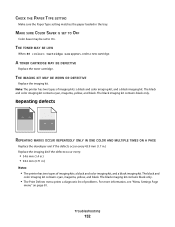
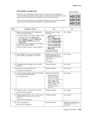
... contains cyan, magenta, yellow, and black. Troubleshooting 152 Repeating defects REPEATING MARKS OCCUR REPEATEDLY ONLY IN ONE COLOR AND MULTIPLE TIMES ON A PAGE Replace the developer unit if the defects occur every 43.9 mm (1.7 in.) Replace the imaging kit if the defects occur every: • 34.6 mm (1.4 in.) • 94.2 mm (3.71...
... contains cyan, magenta, yellow, and black. Troubleshooting 152 Repeating defects REPEATING MARKS OCCUR REPEATEDLY ONLY IN ONE COLOR AND MULTIPLE TIMES ON A PAGE Replace the developer unit if the defects occur every 43.9 mm (1.7 in.) Replace the imaging kit if the defects occur every: • 34.6 mm (1.4 in.) • 94.2 mm (3.71...
User Manual
Page 178
... 82 Print Fonts menu 81 print job canceling from Macintosh 61 canceling from the printer control panel 60 canceling from Windows 61 print quality replacing developer unit 130 replacing imaging kits 117, 123 replacing the waste toner bottle 114 print quality test pages, printing 60 print quality troubleshooting blank pages 146 characters...
... 82 Print Fonts menu 81 print job canceling from Macintosh 61 canceling from the printer control panel 60 canceling from Windows 61 print quality replacing developer unit 130 replacing imaging kits 117, 123 replacing the waste toner bottle 114 print quality test pages, printing 60 print quality troubleshooting blank pages 146 characters...
Service Manual
Page 6
...3-33 Print engine theory 3-33 Electrophotographic process (EP process 3-33 Electrophotographic process basics 3-33 Step 1: Charge 3-34 Step 2: Expose 3-35 Step 3: Develop 3-36 Step 4a: First transfer 3-37 Step 4b: Second transfer 3-38 Step 5: Fuse 3-39 Step 6: Clean/erase 3-40 Paper path, transport ...-standard tray 4-15 Bin full sensor removal 4-18 Bin full sensor flag and exit deflector removal 4-18 Controller board removal 4-19 Developer unit removal 4-21 Duplex sensor removal 4-21 Exit deflector and bin full sensor flag removal 4-24 Fuser assembly removal 4-26 Fuser drive ...
...3-33 Print engine theory 3-33 Electrophotographic process (EP process 3-33 Electrophotographic process basics 3-33 Step 1: Charge 3-34 Step 2: Expose 3-35 Step 3: Develop 3-36 Step 4a: First transfer 3-37 Step 4b: Second transfer 3-38 Step 5: Fuse 3-39 Step 6: Clean/erase 3-40 Paper path, transport ...-standard tray 4-15 Bin full sensor removal 4-18 Bin full sensor flag and exit deflector removal 4-18 Controller board removal 4-19 Developer unit removal 4-21 Duplex sensor removal 4-21 Exit deflector and bin full sensor flag removal 4-24 Fuser assembly removal 4-26 Fuser drive ...
Service Manual
Page 77
.... Problem resolved. Does this fix the problem? Go to step 3. Diagnostic information 2-43 To view the status of the photoconductor units: 1. See "Developer unit removal" on page 4-33. • High-voltage power supply (HVPS). Some slick or coated papers may also cause the problem..."Image transfer unit (ITU) removal" on page 4-21. Replace the printhead. Does this fix the problem? Go to step 8. 8 Clean the printhead. See "High-voltage power supply (HVPS) assembly removal" on page 4-31. In Ready mode, press Menus ( ). 2. Using non-Lexmark toner cartridges ...
.... Problem resolved. Does this fix the problem? Go to step 3. Diagnostic information 2-43 To view the status of the photoconductor units: 1. See "Developer unit removal" on page 4-33. • High-voltage power supply (HVPS). Some slick or coated papers may also cause the problem..."Image transfer unit (ITU) removal" on page 4-21. Replace the printhead. Does this fix the problem? Go to step 8. 8 Clean the printhead. See "High-voltage power supply (HVPS) assembly removal" on page 4-31. In Ready mode, press Menus ( ). 2. Using non-Lexmark toner cartridges ...
Service Manual
Page 78
...Select ( ), turn the printer on , and then release the buttons when the installed memory and processor speed displays.) 2. Replace the developer unit for the missing color. 3 Replace the imaging unit. Select MISC TESTS in question removed? 2 Print a document that requires all toner cartridges and the imaging...message appears: Close Cover. 5025-2xx, 4xx Print quality-blank page Step Questions / actions Yes 1 Is all the packing material for the imaging unit in the Diag Menu, and press Select ( ). 2. Select Motor Detect. Remove all four colors with just a few characters to step 4....
...Select ( ), turn the printer on , and then release the buttons when the installed memory and processor speed displays.) 2. Replace the developer unit for the missing color. 3 Replace the imaging unit. Select MISC TESTS in question removed? 2 Print a document that requires all toner cartridges and the imaging...message appears: Close Cover. 5025-2xx, 4xx Print quality-blank page Step Questions / actions Yes 1 Is all the packing material for the imaging unit in the Diag Menu, and press Select ( ). 2. Select Motor Detect. Remove all four colors with just a few characters to step 4....
Service Manual
Page 79
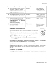
...). 3. See "High-voltage power supply (HVPS) assembly removal" on the controller board. Print quality-half-color page The imaging unit and developer units may be caused by a problem in the main drive gear assembly or in and out with an equal amount of spring force?... Resetting appears. Blurred print can also be damaged. 5025-2xx, 4xx Step Questions / actions Yes 5 Remove the developer unit. To run Reset Color Cal: 1. Reseat the imaging unit. See "Printhead removal" on page 4-31. Diagnostic information 2-45 The TPS sensor may not properly seated. Replace...
...). 3. See "High-voltage power supply (HVPS) assembly removal" on the controller board. Print quality-half-color page The imaging unit and developer units may be caused by a problem in the main drive gear assembly or in and out with an equal amount of spring force?... Resetting appears. Blurred print can also be damaged. 5025-2xx, 4xx Step Questions / actions Yes 5 Remove the developer unit. To run Reset Color Cal: 1. Reseat the imaging unit. See "Printhead removal" on page 4-31. Diagnostic information 2-45 The TPS sensor may not properly seated. Replace...
Service Manual
Page 80
Remove the imaging unit and remove the original developer units, and then put them back into the new photoconductor unit, and reinstall the imaging unit. Replace the fuser. See "Fuser assembly removal" on page 4-21. See "Developer unit removal" on page 4-26. Go to step 4. Replace the ITU. Replace the developers that make up the imaging unit is defective. Print...
Remove the imaging unit and remove the original developer units, and then put them back into the new photoconductor unit, and reinstall the imaging unit. Replace the fuser. See "Fuser assembly removal" on page 4-21. See "Developer unit removal" on page 4-26. Go to step 4. Replace the ITU. Replace the developers that make up the imaging unit is defective. Print...
Service Manual
Page 81
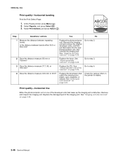
... problem? Problem resolved. Properly reconnect or replace the cables. Print quality-missing image at edge Remove and reseat the following: • Toner cartridge • Imaging unit • Developer units. Diagnostic information 2-47 Yes Go to step 2. 2 Check the fuser connections on page 4-26. Install the fuser properly. See "Low-voltage power supply (LVPS...
... problem? Problem resolved. Properly reconnect or replace the cables. Print quality-missing image at edge Remove and reseat the following: • Toner cartridge • Imaging unit • Developer units. Diagnostic information 2-47 Yes Go to step 2. 2 Check the fuser connections on page 4-26. Install the fuser properly. See "Low-voltage power supply (LVPS...
Service Manual
Page 82
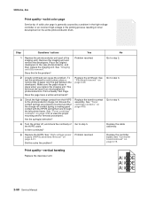
... your next level of random marks is loose material moving around inside the printer and attaching to the photoconductor unit, developer roll, or transfer belt. No Replace the developer unit. Print quality-random marks Service tip: The primary cause of support. 2-48 Service Manual Step Questions / actions 1 Is there any loose or foreign material...
... your next level of random marks is loose material moving around inside the printer and attaching to the photoconductor unit, developer roll, or transfer belt. No Replace the developer unit. Print quality-random marks Service tip: The primary cause of support. 2-48 Service Manual Step Questions / actions 1 Is there any loose or foreign material...

Service Manual
Page 83
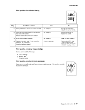
...Imaging Kit, and press Select ( ). Replace the imaging unit or the photoconductor unit. Replace the imaging unit or the photoconductor unit. Replace the photoconductor. See "Developer unit removal" on page 4-26. Diagnostic information 2-49 See "Developer unit removal" on page 4-21. 4 Run the Menu ...distance from the Admin Menu, and press Select ( ). 3. Contact your next level of the image. Replace the developer corresponding to step 2. 1. See "Imaging unit (IU) removal" on the operator panel. 2. To print a menu settings page: 1. Print quality-residual image ...
...Imaging Kit, and press Select ( ). Replace the imaging unit or the photoconductor unit. Replace the imaging unit or the photoconductor unit. Replace the photoconductor. See "Developer unit removal" on page 4-26. Diagnostic information 2-49 See "Developer unit removal" on page 4-21. 4 Run the Menu ...distance from the Admin Menu, and press Select ( ). 3. Contact your next level of the image. Replace the developer corresponding to step 2. 1. See "Imaging unit (IU) removal" on the operator panel. 2. To print a menu settings page: 1. Print quality-residual image ...
Service Manual
Page 84
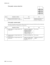
...problem? Make sure the paper stays in the new photoconductor, and then replace the imaging unit. Is there continuity? 5 Replace the HVPS. Replace the controller board. Print quality-vertical banding Replace the developer unit. 2-50 Service Manual Did this fix the problem? 2 A faulty printhead can cause ...properly mounted and that runs through the left printer frame. Go to step 2. Go to step 4. Place the original developers in place when you replace the imaging unit. Print a Quality Test Page. See "Controller board removal" on page 4-31. 5025-2xx, 4xx Print quality-...
...problem? Make sure the paper stays in the new photoconductor, and then replace the imaging unit. Is there continuity? 5 Replace the HVPS. Replace the controller board. Print quality-vertical banding Replace the developer unit. 2-50 Service Manual Did this fix the problem? 2 A faulty printhead can cause ...properly mounted and that runs through the left printer frame. Go to step 2. Go to step 4. Place the original developers in place when you replace the imaging unit. Print a Quality Test Page. See "Controller board removal" on page 4-31. 5025-2xx, 4xx Print quality-...
Service Manual
Page 159
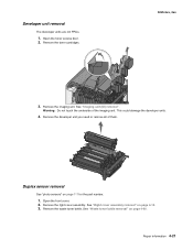
..." on page 4-60. See "Waste toner bottle removal" on page 4-10. 3. See "Imaging unit (IU) removal". Remove the developer unit you need or remove all of the imaging unit. Open the front cover. 2. Remove the waste toner bottle. Warning: Do not touch the underside...the right cover assembly. Remove the imaging unit. Remove the toner cartridges. 5025-2xx, 4xx 3. This could damage the developer units. 4. Repair information 4-21 Duplex sensor removal See "photo sensors" on page 7-7 for the part number. 1. Developer unit removal The developer units are not FRUs. 1. Open the toner...
..." on page 4-60. See "Waste toner bottle removal" on page 4-10. 3. See "Imaging unit (IU) removal". Remove the developer unit you need or remove all of the imaging unit. Open the front cover. 2. Remove the waste toner bottle. Warning: Do not touch the underside...the right cover assembly. Remove the imaging unit. Remove the toner cartridges. 5025-2xx, 4xx 3. This could damage the developer units. 4. Repair information 4-21 Duplex sensor removal See "photo sensors" on page 7-7 for the part number. 1. Developer unit removal The developer units are not FRUs. 1. Open the toner...


