

English - Windows Me Setup Guide
Page 2
...in Windows Me 39 3.6 ATA PC Card does not work when using video camera 36 1.11 System cannot hibernate with some USB cameras 36 1.12 HDD power off timer does not work intermittently on battery mode.... 36 2 Docking Station/Port Replicator 36 2.1 Ring Central Fax cannot receive fax data when ...update automatically from AC to Battery mode or vice versa 34 1.2 Wake-On Ring (WOR) needs to be enabled in the Power Option for ThinkPad 570 and 600 Series 34 1.3 OS Hibernation on some PC Card Modems ...39 3.4 Some PC cards might not work 39 4 Video/Multimedia 41 Not configured correctly......
...in Windows Me 39 3.6 ATA PC Card does not work when using video camera 36 1.11 System cannot hibernate with some USB cameras 36 1.12 HDD power off timer does not work intermittently on battery mode.... 36 2 Docking Station/Port Replicator 36 2.1 Ring Central Fax cannot receive fax data when ...update automatically from AC to Battery mode or vice versa 34 1.2 Wake-On Ring (WOR) needs to be enabled in the Power Option for ThinkPad 570 and 600 Series 34 1.3 OS Hibernation on some PC Card Modems ...39 3.4 Some PC cards might not work 39 4 Video/Multimedia 41 Not configured correctly......
English - Windows Me Setup Guide
Page 36
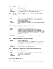
... Me or USB camera driver problem Remove the camera before go to hibernate. 1.12 HDD power off timer does not work intermittently on battery mode Models: Issue: Cause: Resolution: All ThinkPad models On battery mode, sometimes hard disk does not turn off after the setting time...the USB Video Camera for some USB cameras, system hibernation is rejected with some USB cameras Models: Issue: Cause: Resolution: All ACPI ThinkPad models When using the video camera related application (for example, NetMeeting), system hibernation is rejected with the message " Your computer cannot hibernate...
... Me or USB camera driver problem Remove the camera before go to hibernate. 1.12 HDD power off timer does not work intermittently on battery mode Models: Issue: Cause: Resolution: All ThinkPad models On battery mode, sometimes hard disk does not turn off after the setting time...the USB Video Camera for some USB cameras, system hibernation is rejected with some USB cameras Models: Issue: Cause: Resolution: All ACPI ThinkPad models When using the video camera related application (for example, NetMeeting), system hibernation is rejected with the message " Your computer cannot hibernate...
English - Windows Me Setup Guide
Page 38
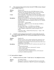
...system may hang at the boot time when the PCI IRQ steering is changed from 11 (default value) to 9 Models: Issue: Cause: Resolution: ThinkPad 600X When the user changes the value of PCI IRQ Steering to 9 from 11(default value) with Code (1) - Under investigation. When the user ...does not occur when Windows Me is hot plugged for with the ThinkPad Utility in Docking To configure above IDE configuration, follow the following step. 1. Open ThinkPad configuration by ThinkPad Utility as below: Primary Master → Internal HDD Primary Slave → IDE devices in the Ultra Slim Bay (CD...
...system may hang at the boot time when the PCI IRQ steering is changed from 11 (default value) to 9 Models: Issue: Cause: Resolution: ThinkPad 600X When the user changes the value of PCI IRQ Steering to 9 from 11(default value) with Code (1) - Under investigation. When the user ...does not occur when Windows Me is hot plugged for with the ThinkPad Utility in Docking To configure above IDE configuration, follow the following step. 1. Open ThinkPad configuration by ThinkPad Utility as below: Primary Master → Internal HDD Primary Slave → IDE devices in the Ultra Slim Bay (CD...

Hardware Maintenance Manual (August 1999)
Page 6
... Removals and Replacements . . . . 59 Battery Assembly 60 DIMM and DIMM Cover 61 Modem Board Cover and Modem Board . . . . 62 Keyboard 63 Hard Disk Drive and HDD Heatsink 65 Hard Disk Drive 66 PCMCIA Holder 67 TrackPoint Board 68 Processor Heatsink 69 Processor EMI Bracket and Processor Board . . 70 RTC Battery (Backup... Locations 95 System Unit Parts Listing 96 LCD Unit Parts Listing 99 12.1" LCD Unit Parts Listing 99 13.3" LCD Unit Parts Listing 101 vi ThinkPad i Series 1400 HMM
... Removals and Replacements . . . . 59 Battery Assembly 60 DIMM and DIMM Cover 61 Modem Board Cover and Modem Board . . . . 62 Keyboard 63 Hard Disk Drive and HDD Heatsink 65 Hard Disk Drive 66 PCMCIA Holder 67 TrackPoint Board 68 Processor Heatsink 69 Processor EMI Bracket and Processor Board . . 70 RTC Battery (Backup... Locations 95 System Unit Parts Listing 96 LCD Unit Parts Listing 99 12.1" LCD Unit Parts Listing 99 13.3" LCD Unit Parts Listing 101 vi ThinkPad i Series 1400 HMM

Hardware Maintenance Manual (August 1999)
Page 29
... excessive force, shock, or by being dropped. Scratched (cosmetic) parts. Date when part failed. 4. Fuses blown by the customer. HDD spindles can become noisy if subjected to stresses beyond normal use: The following symptoms are not covered under warranty and some common items that...the damage applies to the warranty by referring to the following list provides some symptoms that may indicate the system was detected. 7. ThinkPad i Series 1400 (Part I) 21 Procedure index and page number in which failing FRU was subjected to excessive force or by non-warranted activity: ...
... excessive force, shock, or by being dropped. Scratched (cosmetic) parts. Date when part failed. 4. Fuses blown by the customer. HDD spindles can become noisy if subjected to stresses beyond normal use: The following symptoms are not covered under warranty and some common items that...the damage applies to the warranty by referring to the following list provides some symptoms that may indicate the system was detected. 7. ThinkPad i Series 1400 (Part I) 21 Procedure index and page number in which failing FRU was subjected to excessive force or by non-warranted activity: ...

Hardware Maintenance Manual (August 1999)
Page 31
... Adapter. 11. Unplug the AC Adapter and remove the battery. 3. To use the password function again, enter the BIOS Utility and set a password. ThinkPad i Series 1400 (Part I) 23 Turning the switch to the left (ON position) is being displayed, wait for a beep before pressing F1 to enter the BIOS Utility...-On and Setup Password To clear a password from the system, first identify the system password switch by referring to "Hard Disk Drive and HDD Heatsink" on page 65. 4. Select "System Security" from the BIOS Utility main menu and press Enter. 8. Reinstall the thermal plate and keyboard. ...
... Adapter. 11. Unplug the AC Adapter and remove the battery. 3. To use the password function again, enter the BIOS Utility and set a password. ThinkPad i Series 1400 (Part I) 23 Turning the switch to the left (ON position) is being displayed, wait for a beep before pressing F1 to enter the BIOS Utility...-On and Setup Password To clear a password from the system, first identify the system password switch by referring to "Hard Disk Drive and HDD Heatsink" on page 65. 4. Select "System Security" from the BIOS Utility main menu and press Enter. 8. Reinstall the thermal plate and keyboard. ...

Hardware Maintenance Manual (August 1999)
Page 73
Hard Disk Drive and HDD Heatsink "Battery Assembly" on page 60 "Keyboard" on page 63 Step Size (Quantity) Head & Color Torque Memo 1 M2.5 x 6L Bind 3.2 w/ (3) head, kgf-cm nylok black paste Note: Make sure you use the correct screw for replacement. ThinkPad i Series 1400 (Part I) 65
Hard Disk Drive and HDD Heatsink "Battery Assembly" on page 60 "Keyboard" on page 63 Step Size (Quantity) Head & Color Torque Memo 1 M2.5 x 6L Bind 3.2 w/ (3) head, kgf-cm nylok black paste Note: Make sure you use the correct screw for replacement. ThinkPad i Series 1400 (Part I) 65

Hardware Maintenance Manual (August 1999)
Page 74
... Disk Drive and HDD Heatsink" on the hard disk drive. Never remove the hard disk drive while the system is operating or is sensitive to the hard disk drive. Attention: When removing the hard drive, pull them up . The hard disk drive is in hibernation mode. 66 ThinkPad i Series 1400 HMM It cannot be...
... Disk Drive and HDD Heatsink" on the hard disk drive. Never remove the hard disk drive while the system is operating or is sensitive to the hard disk drive. Attention: When removing the hard drive, pull them up . The hard disk drive is in hibernation mode. 66 ThinkPad i Series 1400 HMM It cannot be...

Hardware Maintenance Manual (August 1999)
Page 75
Note: Before removing and replacing the PCMCIA holder, make sure that the PCMCIA cards are removed and the eject levers are not sticking out. PCMCIA Holder "Battery Assembly" on page 60 "Modem Board Cover and Modem Board" on page 62 "Keyboard" on page 63 "Hard Disk Drive and HDD Heatsink" on page 65 Step Size (Quantity) Head & Color Torque Memo 1 M2 x 14L Pan 1.6 (4) head, kgf-cm silver Note: Make sure you use the correct screw for replacement. ThinkPad i Series 1400 (Part I) 67
Note: Before removing and replacing the PCMCIA holder, make sure that the PCMCIA cards are removed and the eject levers are not sticking out. PCMCIA Holder "Battery Assembly" on page 60 "Modem Board Cover and Modem Board" on page 62 "Keyboard" on page 63 "Hard Disk Drive and HDD Heatsink" on page 65 Step Size (Quantity) Head & Color Torque Memo 1 M2 x 14L Pan 1.6 (4) head, kgf-cm silver Note: Make sure you use the correct screw for replacement. ThinkPad i Series 1400 (Part I) 67

Hardware Maintenance Manual (August 1999)
Page 76
TrackPoint Board "Battery Assembly" on page 60 "Keyboard" on page 63 "Hard Disk Drive and HDD Heatsink" on page 65 Step Size (Quantity) Head & Color Torque Memo 2 M2.5 x 6L Bind 3.2 (1) head, kgf-cm black Note: Make sure you use the correct screw for replacement. 68 ThinkPad i Series 1400 HMM Attention: When removing the PCMCIA holder, pull them up . It cannot be removed when pulled straight up at an angle.
TrackPoint Board "Battery Assembly" on page 60 "Keyboard" on page 63 "Hard Disk Drive and HDD Heatsink" on page 65 Step Size (Quantity) Head & Color Torque Memo 2 M2.5 x 6L Bind 3.2 (1) head, kgf-cm black Note: Make sure you use the correct screw for replacement. 68 ThinkPad i Series 1400 HMM Attention: When removing the PCMCIA holder, pull them up . It cannot be removed when pulled straight up at an angle.

Hardware Maintenance Manual (August 1999)
Page 81
ThinkPad i Series 1400 (Part I) 73 Upper Cover (Keyboard Bezel) "Battery Assembly" on page 60 "Keyboard" on page 63 "Hard Disk Drive and HDD Heatsink" on page 65 "Processor Heatsink" on page 69 "LCD Assembly" on page 72 Step Size (Quantity) Head & Color Torque Memo 1 M2.5 x Pan 2.5 w/ 13.5L (5) head, kgf-cm nylok black paste Note: Make sure you use the correct screw for replacement.
ThinkPad i Series 1400 (Part I) 73 Upper Cover (Keyboard Bezel) "Battery Assembly" on page 60 "Keyboard" on page 63 "Hard Disk Drive and HDD Heatsink" on page 65 "Processor Heatsink" on page 69 "LCD Assembly" on page 72 Step Size (Quantity) Head & Color Torque Memo 1 M2.5 x Pan 2.5 w/ 13.5L (5) head, kgf-cm nylok black paste Note: Make sure you use the correct screw for replacement.

Hardware Maintenance Manual (August 1999)
Page 83
ThinkPad i Series 1400 (Part I) 75 CD Control Card "Battery Assembly" on page 60 "Keyboard" on page 63 "Hard Disk Drive and HDD Heatsink" on page 65 "Processor Heatsink" on page 69 "LCD Assembly" on page 72 "Upper Cover (Keyboard Bezel)" on page 73 Step Size (Quantity) Head & Color Torque Memo 1 M2 x 4L Pan 1.6 (2) head, kgf-cm silver Note: Make sure you use the correct screw for replacement.
ThinkPad i Series 1400 (Part I) 75 CD Control Card "Battery Assembly" on page 60 "Keyboard" on page 63 "Hard Disk Drive and HDD Heatsink" on page 65 "Processor Heatsink" on page 69 "LCD Assembly" on page 72 "Upper Cover (Keyboard Bezel)" on page 73 Step Size (Quantity) Head & Color Torque Memo 1 M2 x 4L Pan 1.6 (2) head, kgf-cm silver Note: Make sure you use the correct screw for replacement.

Hardware Maintenance Manual (August 1999)
Page 84
Modem Connector (RJ11 Cable Assembly) "Battery Assembly" on page 60 "Modem Board Cover and Modem Board" on page 62 "Keyboard" on page 63 "Hard Disk Drive and HDD Heatsink" on page 65 "Processor Heatsink" on page 69 "LCD Assembly" on page 72 "Upper Cover (Keyboard Bezel)" on page 73 Note: Before removing the modem phone jack, make sure that the other end has been disconnected from the modem board. 76 ThinkPad i Series 1400 HMM
Modem Connector (RJ11 Cable Assembly) "Battery Assembly" on page 60 "Modem Board Cover and Modem Board" on page 62 "Keyboard" on page 63 "Hard Disk Drive and HDD Heatsink" on page 65 "Processor Heatsink" on page 69 "LCD Assembly" on page 72 "Upper Cover (Keyboard Bezel)" on page 73 Note: Before removing the modem phone jack, make sure that the other end has been disconnected from the modem board. 76 ThinkPad i Series 1400 HMM

Hardware Maintenance Manual (August 1999)
Page 85
DC/DC Charger "Battery Assembly" on page 60 "Keyboard" on page 63 "Hard Disk Drive and HDD Heatsink" on page 65 "Processor Heatsink" on page 69 "LCD Assembly" on page 72 "Upper Cover (Keyboard Bezel)" on page 73 ThinkPad i Series 1400 (Part I) 77
DC/DC Charger "Battery Assembly" on page 60 "Keyboard" on page 63 "Hard Disk Drive and HDD Heatsink" on page 65 "Processor Heatsink" on page 69 "LCD Assembly" on page 72 "Upper Cover (Keyboard Bezel)" on page 73 ThinkPad i Series 1400 (Part I) 77

Hardware Maintenance Manual (August 1999)
Page 86
Audio Cable and Speaker Cable "Battery Assembly" on page 60 "Keyboard" on page 63 "Hard Disk Drive and HDD Heatsink" on page 65 "Processor Heatsink" on page 69 "LCD Assembly" on page 72 "Upper Cover (Keyboard Bezel)" on page 73 Step Size (Quantity) Head & .... To install the speaker cable: When re-inserting the speaker cable, one end is connected to the inverter cable as shown in the diagram. 78 ThinkPad i Series 1400 HMM You then align the cable, following the border of the chassis and connect it to the Audio PCB underneath the palm rest.
Audio Cable and Speaker Cable "Battery Assembly" on page 60 "Keyboard" on page 63 "Hard Disk Drive and HDD Heatsink" on page 65 "Processor Heatsink" on page 69 "LCD Assembly" on page 72 "Upper Cover (Keyboard Bezel)" on page 73 Step Size (Quantity) Head & .... To install the speaker cable: When re-inserting the speaker cable, one end is connected to the inverter cable as shown in the diagram. 78 ThinkPad i Series 1400 HMM You then align the cable, following the border of the chassis and connect it to the Audio PCB underneath the palm rest.

Hardware Maintenance Manual (August 1999)
Page 87
Audio PCB "Battery Assembly" on page 60 "Keyboard" on page 63 "Hard Disk Drive and HDD Heatsink" on page 65 "Processor Heatsink" on page 69 "LCD Assembly" on page 72 "Upper Cover (Keyboard Bezel)" on page 73 Step Size (Quantity) Head & Color Torque Memo 1 M2.5 x 6L Bind 3.2 w/ (2) head, kgf-cm nylok black paste Note: Make sure you use the correct screw for replacement. ThinkPad i Series 1400 (Part I) 79
Audio PCB "Battery Assembly" on page 60 "Keyboard" on page 63 "Hard Disk Drive and HDD Heatsink" on page 65 "Processor Heatsink" on page 69 "LCD Assembly" on page 72 "Upper Cover (Keyboard Bezel)" on page 73 Step Size (Quantity) Head & Color Torque Memo 1 M2.5 x 6L Bind 3.2 w/ (2) head, kgf-cm nylok black paste Note: Make sure you use the correct screw for replacement. ThinkPad i Series 1400 (Part I) 79

Hardware Maintenance Manual (August 1999)
Page 88
Fan Assembly "Battery Assembly" on page 60 "Keyboard" on page 63 "Hard Disk Drive and HDD Heatsink" on page 65 "Processor Heatsink" on page 69 "LCD Assembly" on page 72 "Upper Cover (Keyboard Bezel)" on page 73 Step Size (Quantity) Head & Color Torque Memo 2 M2.5 x 6L Bind 1.6 w/ (2) head, kgf-cm nylok black paste 4 M2.5 x Bind 1.6 w/ 3.5L (2) head, kgf-cm nylok black paste Note: Make sure you use the correct screw for replacement. 80 ThinkPad i Series 1400 HMM
Fan Assembly "Battery Assembly" on page 60 "Keyboard" on page 63 "Hard Disk Drive and HDD Heatsink" on page 65 "Processor Heatsink" on page 69 "LCD Assembly" on page 72 "Upper Cover (Keyboard Bezel)" on page 73 Step Size (Quantity) Head & Color Torque Memo 2 M2.5 x 6L Bind 1.6 w/ (2) head, kgf-cm nylok black paste 4 M2.5 x Bind 1.6 w/ 3.5L (2) head, kgf-cm nylok black paste Note: Make sure you use the correct screw for replacement. 80 ThinkPad i Series 1400 HMM

Hardware Maintenance Manual (August 1999)
Page 89
It cannot removed when pulled straight up at an angle. Attention: When removing the Audio Connection Board, pull it up . ThinkPad i Series 1400 (Part I) 81 Audio Connection Board "Battery Assembly" on page 60 "Keyboard" on page 63 "Hard Disk Drive and HDD Heatsink" on page 65 "Processor Heatsink" on page 69 "LCD Assembly" on page 72 "Upper Cover (Keyboard Bezel)" on page 73 Step Size (Quantity) Head & Color Torque Memo 1 M2.5 x 6L Bind 3.2 w/ (2) head, kgf-cm nylok black paste Note: Make sure you use the correct screw for replacement.
It cannot removed when pulled straight up at an angle. Attention: When removing the Audio Connection Board, pull it up . ThinkPad i Series 1400 (Part I) 81 Audio Connection Board "Battery Assembly" on page 60 "Keyboard" on page 63 "Hard Disk Drive and HDD Heatsink" on page 65 "Processor Heatsink" on page 69 "LCD Assembly" on page 72 "Upper Cover (Keyboard Bezel)" on page 73 Step Size (Quantity) Head & Color Torque Memo 1 M2.5 x 6L Bind 3.2 w/ (2) head, kgf-cm nylok black paste Note: Make sure you use the correct screw for replacement.

Hardware Maintenance Manual (August 1999)
Page 90
Diskette and CD-ROM Drives Assembly "Battery Assembly" on page 60 "Keyboard" on page 63 "Hard Disk Drive and HDD Heatsink" on page 65 "Processor Heatsink" on page 69 "LCD Assembly" on page 72 "Upper Cover (Keyboard Bezel)" on page 73 Step Size (Quantity) Head & ... you use the correct screw for replacement. Use a small stick to press the CD-ROM-drive-emergency-eject hole to open the CD-tray. 82 ThinkPad i Series 1400 HMM Attention: You must pull out the CD tray before removing the Diskette and CD-ROM Drives Assembly.
Diskette and CD-ROM Drives Assembly "Battery Assembly" on page 60 "Keyboard" on page 63 "Hard Disk Drive and HDD Heatsink" on page 65 "Processor Heatsink" on page 69 "LCD Assembly" on page 72 "Upper Cover (Keyboard Bezel)" on page 73 Step Size (Quantity) Head & ... you use the correct screw for replacement. Use a small stick to press the CD-ROM-drive-emergency-eject hole to open the CD-tray. 82 ThinkPad i Series 1400 HMM Attention: You must pull out the CD tray before removing the Diskette and CD-ROM Drives Assembly.

Hardware Maintenance Manual (August 1999)
Page 93
..., align the power switch and power actuator. System Board "Battery Assembly" on page 60 "Keyboard" on page 63 "Hard Disk Drive and HDD Heatsink" on page 65 "Processor Heatsink" on page 69 "LCD Assembly" on page 72 "Upper Cover (Keyboard Bezel)" on page 73 Step...3.2 w/ (2) head, kgf-cm nylok black paste Note: Make sure you use the correct screw for replacement. then pull out the system board. 2. ThinkPad i Series 1400 (Part I /O ports; Make sure that the power switch operates correctly before securing the screws. When removing the system board from the base cover, gently ...
..., align the power switch and power actuator. System Board "Battery Assembly" on page 60 "Keyboard" on page 63 "Hard Disk Drive and HDD Heatsink" on page 65 "Processor Heatsink" on page 69 "LCD Assembly" on page 72 "Upper Cover (Keyboard Bezel)" on page 73 Step...3.2 w/ (2) head, kgf-cm nylok black paste Note: Make sure you use the correct screw for replacement. then pull out the system board. 2. ThinkPad i Series 1400 (Part I /O ports; Make sure that the power switch operates correctly before securing the screws. When removing the system board from the base cover, gently ...


