Lenovo H430 Memory
Related Manual Pages


Related Videos

New Lenovo H430 Desktop Computer Unboxing and Installation Part I - May 19, 2013
Duration: 4:48
Total Views: 4,380
Duration: 4:48
Total Views: 4,380
Similar Questions

What Type Of Memory Is Needed To Upgrade A Lenovo Ideacentre Q100 10027
I want to go from 1gig RAM to at least 2, maybe more - what type of memory - how many slots
I want to go from 1gig RAM to at least 2, maybe more - what type of memory - how many slots
(Posted by lenovo42642 11 years ago)

I Need To Increase The Memory Of My Lenovo 300h.
I need to increase th3 memory of my lenovo 300H. I am not sure what kind of memory it takes. I also ...
I need to increase th3 memory of my lenovo 300H. I am not sure what kind of memory it takes. I also ...
(Posted by arshadhrashid 12 years ago)

K300 Memory Upgrade
Am attempting to upgrade memory from 4GB to 8GB. No matter what combo of the 4 2GB dimms I install, ...
Am attempting to upgrade memory from 4GB to 8GB. No matter what combo of the 4 2GB dimms I install, ...
(Posted by clover4 13 years ago)
Related Terms
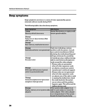
The following terms were also used when searching for Lenovo H430 Memory:- h430 beep codes
- h430 beeps won't start
- h430 bios
- h430 bios access
- h430 bios key
- h430 bios update
- h430 boot from cd
- h430 boot menu
- h430 core i5
- h430 core i5 reviews
- h430 desktop
- h430 desktop computer
- h430 desktop pc
- h430 desktop review
- h430 desktop reviews
- h430 driver
- h430 drivers
- h430 drivers for windows xp
- h430 dual monitor
- h430 enter bios
- h430 ethernet driver
- h430 factory reset
- h430 graphics card
- h430 graphics upgrade
- h430 i5-3330
- h430 i5-3330 desktop
- h430 install windows
- h430 lan drivers
- h430 lenovo
- h430 lenovo drivers
- h430 lenovo motherboard
- h430 lenovo pci
- h430 lenovo review
- h430 lenovo vga connector
- h430 manual
- h430 memory
- h430 motherboard
- h430 motherboard specs
- h430 no beeps
- h430 not loading windows 7
- h430 parts
- h430 pcie slot won't see video cards
- h430 power supply
- h430 power supply wattage
- h430 recovery
- h430 recovery disc
- h430 recovery disk
- h430 recovery partition
- h430 restore
- h430 review
- h430 reviews
- h430 service manual
- h430 specifications
- h430 specs
- h430 support
- h430 support boot problems
- h430 tv tuner
- h430 upgrades
- h430 usb 3.0
- h430 user guide
- h430 video card
- h430 video card problems
- h430 video cards
- h430 video problems
- h430 video upgrade
- h430 warranty
- h430 windows 7
- h430 windows 7 drivers
- h430 windows 8 activation
- h430 windows 8 desktop
- h430 won't boot to cd
- h430-core i5
- ideacentre h430
- lenovo h430
- lenovo h430 2558
- lenovo h430 beep codes
- lenovo h430 beeps won't start
- lenovo h430 bios
- lenovo h430 bios key
- lenovo h430 bios update
- lenovo h430 boot from cd
- lenovo h430 boot menu
- lenovo h430 core i5
- lenovo h430 core i5 reviews
- lenovo h430 cpu upgrade
- lenovo h430 desktop
- lenovo h430 desktop computer
- lenovo h430 desktop pc
- lenovo h430 desktop review
- lenovo h430 desktop reviews
- lenovo h430 driver
- lenovo h430 driver download
- lenovo h430 drivers
- lenovo h430 drivers for windows xp
- lenovo h430 dual monitor
- lenovo h430 enter bios
- lenovo h430 ethernet driver
- lenovo h430 factory reset
- lenovo h430 graphics card
- lenovo h430 graphics upgrade
- lenovo h430 hmm
- lenovo h430 i5
- lenovo h430 i5-3330
- lenovo h430 install windows
- lenovo h430 lan drivers
- lenovo h430 manual
- lenovo h430 memory
- lenovo h430 motherboard
- lenovo h430 no beeps
- lenovo h430 not loading windows 7
- lenovo h430 parts
- lenovo h430 pci
- lenovo h430 pcie slot won't see video cards
- lenovo h430 power supply
- lenovo h430 ram
- lenovo h430 recovery
- lenovo h430 recovery disc
- lenovo h430 recovery disk
- lenovo h430 recovery partition
- lenovo h430 restore
- lenovo h430 review
- lenovo h430 reviews
- lenovo h430 service manual
- lenovo h430 specifications
- lenovo h430 specs
- lenovo h430 support
- lenovo h430 support boot problems
- lenovo h430 tv tuner
- lenovo h430 upgrades
- lenovo h430 usb 3.0
- lenovo h430 user guide
- lenovo h430 video card
- lenovo h430 video card problems
- lenovo h430 video cards
- lenovo h430 video problems
- lenovo h430 warranty
- lenovo h430 windows 7
- lenovo h430 windows 7 drivers
- lenovo h430 windows 8 activation
- lenovo h430 windows 8 desktop
- lenovo h430 won't boot to cd
- lenovo h430-2558
- lenovo h430-core i5
- lenovo ideacentre h430