H430 Power Supply - Lenovo
H430 Power Supply
Related Manual Pages

Related Videos

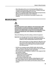
Lenovo H430 heatsink fan causing computer not to boot when wires too close to fan.
Duration: :32
Total Views: 564
Duration: :32
Total Views: 564
Similar Questions

Power Supply Connections To Mother Board
I need to find out where one of the connections to the mother board from power supply go to. I can s...
I need to find out where one of the connections to the mother board from power supply go to. I can s...
(Posted by bobwilk12345 8 years ago)


Can I Add A Graphics Card To The Lenovo H430 Without Changing The Power Supply?
(Posted by paumil 10 years ago)

Power Supply
want to update power supply , wanted to know what to get ?
want to update power supply , wanted to know what to get ?
(Posted by babyleverton 11 years ago)