Hardware Maintenance Manual
Page 3
... 24 Power-on password 24 Supervisor password 24 Power management 25 Screen blank mode 25 Sleep (standby) mode 25 Hibernation mode 26 Lenovo G470/G475/G570/G575 27 Specifications 27 Status indicators 29 Fn key combinations 31 FRU replacement notices 32 Screw notices 32 Removing and replacing an FRU 33 ... board 53 1140 LCD unit 56 1150 Speakers, bluetooth daughter card and base cover 59 1160 LCD front bezel 64 1170 LCD panel and hinges 65 1180 Integrated camera 67 1190 Antenna assembly and LCD cover ..........68 Locations 69 Front view 69 Right-side view 70 Bottom and Left-...
... 24 Power-on password 24 Supervisor password 24 Power management 25 Screen blank mode 25 Sleep (standby) mode 25 Hibernation mode 26 Lenovo G470/G475/G570/G575 27 Specifications 27 Status indicators 29 Fn key combinations 31 FRU replacement notices 32 Screw notices 32 Removing and replacing an FRU 33 ... board 53 1140 LCD unit 56 1150 Speakers, bluetooth daughter card and base cover 59 1160 LCD front bezel 64 1170 LCD panel and hinges 65 1180 Integrated camera 67 1190 Antenna assembly and LCD cover ..........68 Locations 69 Front view 69 Right-side view 70 Bottom and Left-...
Hardware Maintenance Manual
Page 69
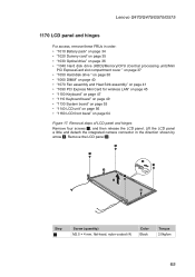
... four screws 1, and then release the LCD panel. Lenovo G470/G475/G570/G575 1170 LCD panel and hinges For access, remove these FRUs in the direction shown by arrow 2. Lift the LCD panel a little and detach the integrated camera connector in order: •&#...
... four screws 1, and then release the LCD panel. Lenovo G470/G475/G570/G575 1170 LCD panel and hinges For access, remove these FRUs in the direction shown by arrow 2. Lift the LCD panel a little and detach the integrated camera connector in order: •&#...
Hardware Maintenance Manual
Page 70
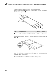
Removal steps of LCD panel and hinges (continued) Remove eight screws 4, and release the hinges from the LCD panel in the direction shown by arrows 5. 5 4 4 4 4 4 4 4 4 5 Step 4 Screw (quantity) M2.0 × 3 mm, flat-head, nylon-coated (8) Color Black Torque 2.0kgfcm Detach ...the connector on the back of the LCD panel in the direction shown by arrow 6. 6 Note: The LCD circuit is attached firmly. 66 Lenovo G470/G475/G570/G575 Hardware Maintenance Manual Figure 17. When installing: Make sure that the connector is attached to the LCD panel, and connected with the LCD cable...
Removal steps of LCD panel and hinges (continued) Remove eight screws 4, and release the hinges from the LCD panel in the direction shown by arrows 5. 5 4 4 4 4 4 4 4 4 5 Step 4 Screw (quantity) M2.0 × 3 mm, flat-head, nylon-coated (8) Color Black Torque 2.0kgfcm Detach ...the connector on the back of the LCD panel in the direction shown by arrow 6. 6 Note: The LCD circuit is attached firmly. 66 Lenovo G470/G475/G570/G575 Hardware Maintenance Manual Figure 17. When installing: Make sure that the connector is attached to the LCD panel, and connected with the LCD cable...
Hardware Maintenance Manual
Page 71
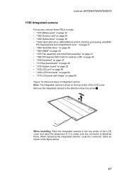
Lenovo G470/G475/G570/G575 1180 Integrated camera For access, remove these FRUs in the figure above. 67 Removal steps of integrated camera Note: The integrated camera is attached firmly. ... page 53 •• "1140 LCD unit" on page 56 •• "1160 LCD front bezel" on page 64 •• "1170 LCD panel and hinges" on the top center of it to the top center of the LCD cover and ajust the placement of the LCD cover. Remove the integrated...
Lenovo G470/G475/G570/G575 1180 Integrated camera For access, remove these FRUs in the figure above. 67 Removal steps of integrated camera Note: The integrated camera is attached firmly. ... page 53 •• "1140 LCD unit" on page 56 •• "1160 LCD front bezel" on page 64 •• "1170 LCD panel and hinges" on the top center of it to the top center of the LCD cover and ajust the placement of the LCD cover. Remove the integrated...
Hardware Maintenance Manual
Page 72
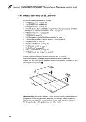
... page 53 •• "1140 LCD unit" on page 56 •• "1160 LCD front bezel" on page 64 •• "1170 LCD panel and hinges" on page 65 Figure 19. Tension could cause the cables to be broken. 68 As you route the cables, make sure that they are not... subjected to any tension. Lenovo G470/G475/G570/G575 Hardware Maintenance Manual 1190 Antenna assembly and LCD cover For access, remove these FRUs in the direction shown by the cable guides, or a wire...
... page 53 •• "1140 LCD unit" on page 56 •• "1160 LCD front bezel" on page 64 •• "1170 LCD panel and hinges" on page 65 Figure 19. Tension could cause the cables to be broken. 68 As you route the cables, make sure that they are not... subjected to any tension. Lenovo G470/G475/G570/G575 Hardware Maintenance Manual 1190 Antenna assembly and LCD cover For access, remove these FRUs in the direction shown by the cable guides, or a wire...


