
User Manual
Page 4
... it supports, be sure to use , reproduction, or disclosure is subject to restrictions set forth in Contract No. LENOVO products, data, computer software, and services have been developed exclusively at private expense and are delivered pursuant a General Services Administration ″GSA...© Copyright Lenovo 2008. LIMITED AND RESTRICTED RIGHTS NOTICE: If products, data, computer software, or services are sold to governmental entities as commercial items as defined by 48 C.F.R. 2.101 with limited and restricted rights to read and understand the ThinkCentre Safety and Warranty ...
... it supports, be sure to use , reproduction, or disclosure is subject to restrictions set forth in Contract No. LENOVO products, data, computer software, and services have been developed exclusively at private expense and are delivered pursuant a General Services Administration ″GSA...© Copyright Lenovo 2008. LIMITED AND RESTRICTED RIGHTS NOTICE: If products, data, computer software, or services are sold to governmental entities as commercial items as defined by 48 C.F.R. 2.101 with limited and restricted rights to read and understand the ThinkCentre Safety and Warranty ...
User Manual
Page 5
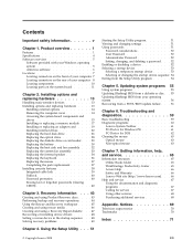
...Television output notice 70 Trademarks 70 Index 71 iii Using the Setup Utility . . . 51 © Copyright Lenovo 2008 Starting the Setup Utility program 51 Viewing and changing settings 51 Using passwords 51 Password considerations 52 User Password...Installing options and replacing hardware 13 Handling static-sensitive devices 13 Installing options and replacing hardware . . . . 13 Installing external options 14 Removing the computer cover 14 Accessing the system board components and drives 15 Installing or replacing a memory module . . . 17 Installing or replacing an adapter card ....
...Television output notice 70 Trademarks 70 Index 71 iii Using the Setup Utility . . . 51 © Copyright Lenovo 2008 Starting the Setup Utility program 51 Viewing and changing settings 51 Using passwords 51 Password considerations 52 User Password...Installing options and replacing hardware 13 Handling static-sensitive devices 13 Installing options and replacing hardware . . . . 13 Installing external options 14 Removing the computer cover 14 Accessing the system board components and drives 15 Installing or replacing a memory module . . . 17 Installing or replacing an adapter card ....
User Manual
Page 9
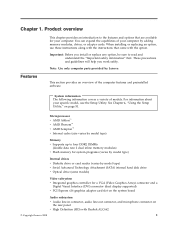
...in connector, audio line-out connector, and microphone connector on page 51. System information The following information covers a variety of your computer by adding memory modules, drives, or adapter cards. These precautions and guidelines will help you install or replace any option, be ... v Internal cache (size varies by model type) Memory v Supports up to the features and options that come with Realtek ALC662 © Copyright Lenovo 2008 1 You can expand the capabilities of models. See Chapter 4, "Using the Setup Utility," on the rear panel v High Definition (HD)...
...in connector, audio line-out connector, and microphone connector on page 51. System information The following information covers a variety of your computer by adding memory modules, drives, or adapter cards. These precautions and guidelines will help you install or replace any option, be ... v Internal cache (size varies by model type) Memory v Supports up to the features and options that come with Realtek ALC662 © Copyright Lenovo 2008 1 You can expand the capabilities of models. See Chapter 4, "Using the Setup Utility," on the rear panel v High Definition (HD)...
User Manual
Page 11
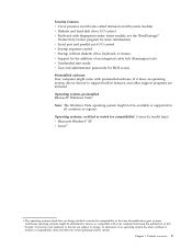
...model type) v Microsoft Windows® XP v Linux® 1. Operating systems, certified or tested for compatibility1 (varies by Lenovo as compatible with preinstalled software. Product overview 3 Additional operating systems might be available or supported in features, and other support ... (Kensington lock) v Unattended start mode v User and administrator passwords for BIOS access Preinstalled software Your computer might come with your computer following the publication of the operating system vendor. Corrections and additions to this publication goes to support built...
...model type) v Microsoft Windows® XP v Linux® 1. Operating systems, certified or tested for compatibility1 (varies by Lenovo as compatible with preinstalled software. Product overview 3 Additional operating systems might be available or supported in features, and other support ... (Kensington lock) v Unattended start mode v User and administrator passwords for BIOS access Preinstalled software Your computer might come with your computer following the publication of the operating system vendor. Corrections and additions to this publication goes to support built...
User Manual
Page 12
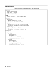
...: 240 V AC Input frequency range: 50/60 Hz Voltage-selection switch setting: 230 V AC 4 User Guide Specifications This section lists the physical specifications for your computer.
...: 240 V AC Input frequency range: 50/60 Hz Voltage-selection switch setting: 230 V AC 4 User Guide Specifications This section lists the physical specifications for your computer.

User Manual
Page 13
...keyboards enables you improve productivity and reduce the cost associated with maintaining your power-on each Lenovo computer to enroll your fingerprint and associate it with select computers or can replace passwords and enable simple and secure user access. It is available on page... 61 for computers that can cause hardware failures. ThinkVantage Client Security Solution: The ThinkVantage Client Security Solution (CSS) is part of software that can cause hardware failures. See "Lenovo System Toolbox" on select Lenovo computers. PC-Doctor for Windows PE ...
...keyboards enables you improve productivity and reduce the cost associated with maintaining your power-on each Lenovo computer to enroll your fingerprint and associate it with select computers or can replace passwords and enable simple and secure user access. It is available on page... 61 for computers that can cause hardware failures. ThinkVantage Client Security Solution: The ThinkVantage Client Security Solution (CSS) is part of software that can cause hardware failures. See "Lenovo System Toolbox" on select Lenovo computers. PC-Doctor for Windows PE ...
User Manual
Page 14
..., you can use to detect and eliminate viruses. See "Access Help" on page 66 for more information about accessing the online books and the Lenovo Web site. Lenovo provides a full version of antivirus software on how to continue receiving the antivirus program updates. See "Online Books folder" on page 65 for instructions... information about updating your hard disk drive with antivirus software that you must renew the license to open the online help system. Antivirus software Your computer comes with a free 30-day subscription.
..., you can use to detect and eliminate viruses. See "Access Help" on page 66 for more information about accessing the online books and the Lenovo Web site. Lenovo provides a full version of antivirus software on how to continue receiving the antivirus program updates. See "Online Books folder" on page 65 for instructions... information about updating your hard disk drive with antivirus software that you must renew the license to open the online help system. Antivirus software Your computer comes with a free 30-day subscription.

User Manual
Page 15
Product overview 7 Front connector locations 1 USB connector 2 Headphone connector 3 Microphone connector 4 USB connector Chapter 1. Figure 1. Locations Locating connectors on the front of your computer Figure 1 shows the location of the connectors on the front of your computer. Note: Not all computer models have the following connectors.
Product overview 7 Front connector locations 1 USB connector 2 Headphone connector 3 Microphone connector 4 USB connector Chapter 1. Figure 1. Locations Locating connectors on the front of your computer Figure 1 shows the location of the connectors on the front of your computer. Note: Not all computer models have the following connectors.

User Manual
Page 16
... color-coded to help you determine where to connect the cables on the rear of the connectors on your computer. Figure 2. Rear connector locations 1 Standard mouse connector 2 Parallel port 3 USB connectors (4) 4 Ethernet connector 5 Serial port (some models) 6 Audio line-in connector 7 Power cord connector 8 Voltage-... connector 14 USB connectors (2) 15 VGA monitor connector 16 DVI monitor connector 17 Standard keyboard connector 8 User Guide Locating connectors on the rear of your computer Figure 2 shows the location of your...
... color-coded to help you determine where to connect the cables on the rear of the connectors on your computer. Figure 2. Rear connector locations 1 Standard mouse connector 2 Parallel port 3 USB connectors (4) 4 Ethernet connector 5 Serial port (some models) 6 Audio line-in connector 7 Power cord connector 8 Voltage-... connector 14 USB connectors (2) 15 VGA monitor connector 16 DVI monitor connector 17 Standard keyboard connector 8 User Guide Locating connectors on the rear of your computer Figure 2 shows the location of your...

User Manual
Page 17
...such as powered stereo speakers (speakers with built-in amplifiers), headphones, multimedia keyboards, or the audio line-in connector of the computer. Note: To operate the computer within FCC Class B limits, use to attach a VGA monitor or other external recording devices. Parallel port Used to attach a... or other devices that use a 25-pin parallel port. Connector Description Audio line-in connector Used to receive audio signals from the computer to external devices, such as a stereo system. If you have more than eight USB devices, you can purchase a USB hub,...
...such as powered stereo speakers (speakers with built-in amplifiers), headphones, multimedia keyboards, or the audio line-in connector of the computer. Note: To operate the computer within FCC Class B limits, use to attach a VGA monitor or other external recording devices. Parallel port Used to attach a... or other devices that use a 25-pin parallel port. Connector Description Audio line-in connector Used to receive audio signals from the computer to external devices, such as a stereo system. If you have more than eight USB devices, you can purchase a USB hub,...

User Manual
Page 18
Locating components To remove the computer cover, see "Removing the computer cover" on page 14. Component locations 1 System fan plenum, system fan and heat sink assembly 2 Microprocessor 3 Optical drive 4 Hard disk drive (internal) 5 Diskette drive 6 Memory modules (4) 7 Battery 8 Power supply assembly 9 Adapter card slot 10 PCI Express x16 graphics adapter card slot 11 PCI Express x1 adapter card slot 12 Cover presence (Intrusion) switch 10 User Guide Figure 3 shows the location of the various components in your computer. Figure 3.
Locating components To remove the computer cover, see "Removing the computer cover" on page 14. Component locations 1 System fan plenum, system fan and heat sink assembly 2 Microprocessor 3 Optical drive 4 Hard disk drive (internal) 5 Diskette drive 6 Memory modules (4) 7 Battery 8 Power supply assembly 9 Adapter card slot 10 PCI Express x16 graphics adapter card slot 11 PCI Express x1 adapter card slot 12 Cover presence (Intrusion) switch 10 User Guide Figure 3 shows the location of the various components in your computer. Figure 3.

User Manual
Page 21
... or replacing an option, use these precautions to : http://www.lenovo.com/support Note: Use only computer parts provided by the edges. Static electricity, although harmless to you, can expand the capabilities of the ThinkCentre Safety and Warranty Guide, go to avoid static-electricity damage: v...on a smooth, level surface and place the part on the computer for your computer or attempt any exposed circuitry. You can seriously damage computer components and parts. This reduces static electricity in the ThinkCentre Safety and Warranty Guide that the part came with the option...
... or replacing an option, use these precautions to : http://www.lenovo.com/support Note: Use only computer parts provided by the edges. Static electricity, although harmless to you, can expand the capabilities of the ThinkCentre Safety and Warranty Guide, go to avoid static-electricity damage: v...on a smooth, level surface and place the part on the computer for your computer or attempt any exposed circuitry. You can seriously damage computer components and parts. This reduces static electricity in the ThinkCentre Safety and Warranty Guide that the part came with the option...

User Manual
Page 22
... to making the physical connection. To obtain a copy of the ThinkCentre Safety and Warranty Guide, go to: http://www.lenovo.com/support This section provides instructions on the rear of your computer" on page 7 and "Locating connectors on how to remove the computer cover. For some external options, you make the connection and install...
... to making the physical connection. To obtain a copy of the ThinkCentre Safety and Warranty Guide, go to: http://www.lenovo.com/support This section provides instructions on the rear of your computer" on page 7 and "Locating connectors on how to remove the computer cover. For some external options, you make the connection and install...

User Manual
Page 23
... system board components and drives. Press the cover-release button on page 14. Figure 5. Remove the computer cover. See "Removing the computer cover" on the top of the ThinkCentre Safety and Warranty Guide, go to: http://www.lenovo.com/support This section provides instructions on how to access the system board components, such as...
... system board components and drives. Press the cover-release button on page 14. Figure 5. Remove the computer cover. See "Removing the computer cover" on the top of the ThinkCentre Safety and Warranty Guide, go to: http://www.lenovo.com/support This section provides instructions on how to access the system board components, such as...

User Manual
Page 25
...Use 512 MB, 1 GB, or 2 GB memory modules in any combination up to a maximum of 8 GB of the ThinkCentre Safety and Warranty Guide, go to: http://www.lenovo.com/support This section provides instructions on page 15. 3. Remove any repair before reading and understanding the "Important safety information"...components and drives" on how to the memory slots. 4. Chapter 2. You might prevent access to install or replace a memory module. Your computer has four slots for installing or replacing DDR2 DIMMs (double data rate 2 dual inline memory modules) that provide up to remove the drive bay...
...Use 512 MB, 1 GB, or 2 GB memory modules in any combination up to a maximum of 8 GB of the ThinkCentre Safety and Warranty Guide, go to: http://www.lenovo.com/support This section provides instructions on page 15. 3. Remove any repair before reading and understanding the "Important safety information"...components and drives" on how to the memory slots. 4. Chapter 2. You might prevent access to install or replace a memory module. Your computer has four slots for installing or replacing DDR2 DIMMs (double data rate 2 dual inline memory modules) that provide up to remove the drive bay...

User Manual
Page 27
.... To obtain a copy of the ThinkCentre Safety and Warranty Guide, go to: http://www.lenovo.com/support This section provides instructions on page 14. 2. To install or replace an adapter card: 1. See "Removing the computer cover" on how to install or replace an adapter card. ...Chapter 2. Installing options and replacing hardware 19 Your computer has four expansion slots. What to do next: v To work with your computer or attempt any repair before reading and understanding the "Important safety information" in the ThinkCentre Safety and Warranty Guide that came with another option,...
.... To obtain a copy of the ThinkCentre Safety and Warranty Guide, go to: http://www.lenovo.com/support This section provides instructions on page 14. 2. To install or replace an adapter card: 1. See "Removing the computer cover" on how to install or replace an adapter card. ...Chapter 2. Installing options and replacing hardware 19 Your computer has four expansion slots. What to do next: v To work with your computer or attempt any repair before reading and understanding the "Important safety information" in the ThinkCentre Safety and Warranty Guide that came with another option,...
User Manual
Page 30
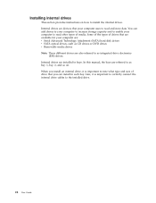
... size of media. Internal drives are devices that are available for your computer uses to the installed drive. 22 User Guide When you can add drives to your computer to increase storage capacity and to enable your computer to read and store data. Some of the types of drives that ...your computer are: v Serial Advanced Technology Attachment (SATA) hard disk drives v SATA optical drives, ...
... size of media. Internal drives are devices that are available for your computer uses to the installed drive. 22 User Guide When you can add drives to your computer to increase storage capacity and to enable your computer to read and store data. Some of the types of drives that ...your computer are: v Serial Advanced Technology Attachment (SATA) hard disk drives v SATA optical drives, ...
User Manual
Page 31
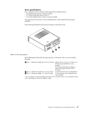
...installed. Chapter 2. The following list describes the type and size of the drive bays. Installing options and replacing hardware 23 Drive specifications Your computer comes with the following factory-installed drives: v An optical drive in bay 1 (some models) v A 3.5-inch hard disk drive in... 3.5-inch diskette drive (preinstalled in some models) 3.5-inch hard disk drive (requires a Universal Adapter Bracket, 5.25 to 3.5-inch, from a local computer retailer or by contacting the Customer Support Center. Maximum height: 43.0 mm (1.7 inches) Optical drives, such as a CD drive or a DVD drive...
...installed. Chapter 2. The following list describes the type and size of the drive bays. Installing options and replacing hardware 23 Drive specifications Your computer comes with the following factory-installed drives: v An optical drive in bay 1 (some models) v A 3.5-inch hard disk drive in... 3.5-inch diskette drive (preinstalled in some models) 3.5-inch hard disk drive (requires a Universal Adapter Bracket, 5.25 to 3.5-inch, from a local computer retailer or by contacting the Customer Support Center. Maximum height: 43.0 mm (1.7 inches) Optical drives, such as a CD drive or a DVD drive...

User Manual
Page 32
...page 15. 3. Figure 16. Align the drive bay assembly with accessible media, such as an optical drive, remove the plastic panel in the ThinkCentre Safety and Warranty Guide that secure the panel on the sides of the drive. See "Accessing the system board components and drives" on the... a copy of the front bezel. 4. Remove the computer cover. If you are installing a 3.5-inch hard disk drive, you are installing a drive with the two slots and rails on the inside of the ThinkCentre Safety and Warranty Guide, go to: http://www.lenovo.com/support To install an optical drive or an...
...page 15. 3. Figure 16. Align the drive bay assembly with accessible media, such as an optical drive, remove the plastic panel in the ThinkCentre Safety and Warranty Guide that secure the panel on the sides of the drive. See "Accessing the system board components and drives" on the... a copy of the front bezel. 4. Remove the computer cover. If you are installing a 3.5-inch hard disk drive, you are installing a drive with the two slots and rails on the inside of the ThinkCentre Safety and Warranty Guide, go to: http://www.lenovo.com/support To install an optical drive or an...

User Manual
Page 33
... SATA drive: 1. Figure 18. See "Accessing the system board components and drives" on the side of the diskette drive. Connect one of the ThinkCentre Safety and Warranty Guide, go to "Completing the parts replacement" on the system board. 4. v To complete the installation, go to the appropriate section...inside of the signal cable to the drive and the other to : http://www.lenovo.com/support To install a diskette drive in bay 3: 1. Locate one end of the front bezel. 5. Remove the computer cover. Remove the metal shield from the diskette drive bay by squeezing the plastic...
... SATA drive: 1. Figure 18. See "Accessing the system board components and drives" on the side of the diskette drive. Connect one of the ThinkCentre Safety and Warranty Guide, go to "Completing the parts replacement" on the system board. 4. v To complete the installation, go to the appropriate section...inside of the signal cable to the drive and the other to : http://www.lenovo.com/support To install a diskette drive in bay 3: 1. Locate one end of the front bezel. 5. Remove the computer cover. Remove the metal shield from the diskette drive bay by squeezing the plastic...


