
User Manual
Page 10
...Peripheral Component Interconnect (PCI) V.90 Data/Fax modem (some models) System management features v Ability to store power-on self-test (POST) hardware test results v ASF 2.0 (Alert Standard Format Specification) v Automatic power-on startup v Preboot Execution Environment (PXE) and Dynamic Host Configuration Protocol (DHCP) v Remote Administration v ...PCI adapter card slots v One PCI Express x1 adapter card slot v One PCI Express x16 graphics adapter card slot Power v 280-watt auto-sensing power supply (some models) v Automatic 50/60 Hz input frequency switching v Advanced Configuration and...
...Peripheral Component Interconnect (PCI) V.90 Data/Fax modem (some models) System management features v Ability to store power-on self-test (POST) hardware test results v ASF 2.0 (Alert Standard Format Specification) v Automatic power-on startup v Preboot Execution Environment (PXE) and Dynamic Host Configuration Protocol (DHCP) v Remote Administration v ...PCI adapter card slots v One PCI Express x1 adapter card slot v One PCI Express x16 graphics adapter card slot Power v 280-watt auto-sensing power supply (some models) v Automatic 50/60 Hz input frequency switching v Advanced Configuration and...

User Manual
Page 18
Locating components To remove the computer cover, see "Removing the computer cover" on page 14. Figure 3 shows the location of the various components in your computer. Component locations 1 System fan plenum, system fan and heat sink assembly 2 Microprocessor 3 Optical drive 4 Hard disk drive (internal) 5 Diskette drive 6 Memory modules (4) 7 Battery 8 Power supply assembly 9 Adapter card slot 10 PCI Express x16 graphics adapter card slot 11 PCI Express x1 adapter card slot 12 Cover presence (Intrusion) switch 10 User Guide Figure 3.
Locating components To remove the computer cover, see "Removing the computer cover" on page 14. Figure 3 shows the location of the various components in your computer. Component locations 1 System fan plenum, system fan and heat sink assembly 2 Microprocessor 3 Optical drive 4 Hard disk drive (internal) 5 Diskette drive 6 Memory modules (4) 7 Battery 8 Power supply assembly 9 Adapter card slot 10 PCI Express x16 graphics adapter card slot 11 PCI Express x1 adapter card slot 12 Cover presence (Intrusion) switch 10 User Guide Figure 3.
User Manual
Page 46
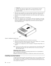
...is typed in readme files with the two slots and rails on page 51. Figure 37. Note: In most areas of the world, Lenovo requires the return of the computer chassis. 3. In addition to physical locks, unauthorized use of your configuration, refer to Chapter 4, "Using ...has screws that are not preinstalled at: http://www.lenovo.com/support Installation instructions are available. Install any locking devices such as a padlock as necessary. 8. If the drive bay assembly was removed. 6. Important Correctly route all power supply cables to avoid interference with the CRU or will...
...is typed in readme files with the two slots and rails on page 51. Figure 37. Note: In most areas of the world, Lenovo requires the return of the computer chassis. 3. In addition to physical locks, unauthorized use of your configuration, refer to Chapter 4, "Using ...has screws that are not preinstalled at: http://www.lenovo.com/support Installation instructions are available. Install any locking devices such as a padlock as necessary. 8. If the drive bay assembly was removed. 6. Important Correctly route all power supply cables to avoid interference with the CRU or will...


