
Service Manual
Page 1
website:http://biz.LGservice.com e-mail:http://www.LGEservice.com/techsup.html LCD TV SERVICE MANUAL CHASSIS : ML-041B MODEL: RZ-15LA70(RZ-15LA70 Rev A) *( ) ID LABEL Model No. R *Same looking with new chassis *Issue Date; 2004. 06 CAUTION BEFORE SERVICING THE CHASSIS, READ THE SAFETY PRECAUTIONS IN THIS MANUAL.
website:http://biz.LGservice.com e-mail:http://www.LGEservice.com/techsup.html LCD TV SERVICE MANUAL CHASSIS : ML-041B MODEL: RZ-15LA70(RZ-15LA70 Rev A) *( ) ID LABEL Model No. R *Same looking with new chassis *Issue Date; 2004. 06 CAUTION BEFORE SERVICING THE CHASSIS, READ THE SAFETY PRECAUTIONS IN THIS MANUAL.
Service Manual
Page 2
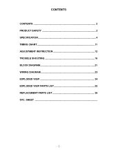
SHEET CONTENTS CONTENTS 2 PRODUCT SAFETY 3 SPECIFICATION 4 TIMING CHART 11 ADJUSTMENT INSTRUCTION 12 TROUBLE SHOOTING 16 BLOCK DIAGRAM 21 WIRING DIAGRAM 23 EXPLODED VIEW 24 EXPLODED VIEW PARTS LIST 25 REPLACEMENT PARTS LIST 26 SVC.
SHEET CONTENTS CONTENTS 2 PRODUCT SAFETY 3 SPECIFICATION 4 TIMING CHART 11 ADJUSTMENT INSTRUCTION 12 TROUBLE SHOOTING 16 BLOCK DIAGRAM 21 WIRING DIAGRAM 23 EXPLODED VIEW 24 EXPLODED VIEW PARTS LIST 25 REPLACEMENT PARTS LIST 26 SVC.
Service Manual
Page 3
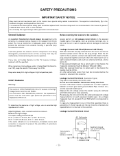
... protection, the replacement panel must be inadvertently introduced during the servicing of adequate power rating as specified in this protects the technician from accidents resulting in the Schematic Diagram and Replacement Parts List. Measure the high voltage. Before returning the receiver to the customer, always perform an AC leakage current check on position, connect one lead of premature component failure. If...
... protection, the replacement panel must be inadvertently introduced during the servicing of adequate power rating as specified in this protects the technician from accidents resulting in the Schematic Diagram and Replacement Parts List. Measure the high voltage. Before returning the receiver to the customer, always perform an AC leakage current check on position, connect one lead of premature component failure. If...
Service Manual
Page 4
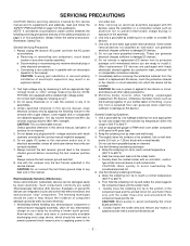
.... 4. CAUTION: Work quickly to solder or unsolder ES devices. 4. c. Closely inspect the solder area and remove any heat sink in this service manual, clean electrical contacts only by applying the following mixture to help reduce the incidence of your foot from the AC power source before connecting the test receiver positive lead. Always unplug the receiver AC power cord from a carpeted...
.... 4. CAUTION: Work quickly to solder or unsolder ES devices. 4. c. Closely inspect the solder area and remove any heat sink in this service manual, clean electrical contacts only by applying the following mixture to help reduce the incidence of your foot from the AC power source before connecting the test receiver positive lead. Always unplug the receiver AC power cord from a carpeted...

Service Manual
Page 5
... it. 3. Replacement 1. Power Output, Transistor Device Removal/Replacement 1. CAUTION: Maintain original spacing between the replaced component and adjacent components and the circuit board to the areas). Remove the defective copper pattern with a sharp knife. (Remove only as much copper as possible to repair the defective copper pattern at top of the good copper pattern. Carefully crimp and solder the connections. Clean the...
... it. 3. Replacement 1. Power Output, Transistor Device Removal/Replacement 1. CAUTION: Maintain original spacing between the replaced component and adjacent components and the circuit board to the areas). Remove the defective copper pattern with a sharp knife. (Remove only as much copper as possible to repair the defective copper pattern at top of the good copper pattern. Carefully crimp and solder the connections. Clean the...
Service Manual
Page 6
... Color Depth Size [mm] Surface Treatment Operating Mode Back light Unit R/T Typ. 2 Maker Type ActiveDisplay Area Pixel Pitch [mm] Electrical Interface Color Depth Size [mm] Surface Treatment Operating Mode Back light Unit R/T Typ. 3 Maker Type ActiveDisplay Area Pixel Pitch [mm] Electrical Interface Color Depth Size [mm] Surface Treatment Operating Mode Back light Unit R/T Typ. Glare (3H) Normally Black 4 CCFL(4 lamps) T total(Tr+Td) = 25ms CMO TFT Color LCD Module 15.0 inches...
... Color Depth Size [mm] Surface Treatment Operating Mode Back light Unit R/T Typ. 2 Maker Type ActiveDisplay Area Pixel Pitch [mm] Electrical Interface Color Depth Size [mm] Surface Treatment Operating Mode Back light Unit R/T Typ. 3 Maker Type ActiveDisplay Area Pixel Pitch [mm] Electrical Interface Color Depth Size [mm] Surface Treatment Operating Mode Back light Unit R/T Typ. Glare (3H) Normally Black 4 CCFL(4 lamps) T total(Tr+Td) = 25ms CMO TFT Color LCD Module 15.0 inches...
Service Manual
Page 7
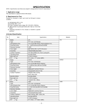
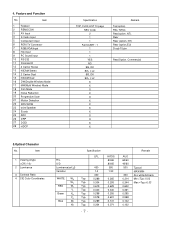
4. Feature and Function No. Item 1 Viewing Angle 2 Luminance 3 Contrast Ratio 4 CIE Color Coordinates R/L, U/D Luminance(cd/ ) Variation WHITE WX WY RED Wr Yr Green Xg Yg Blue Xb Yb Specification LPL 450 1.3 400 Typ. 0.289 Typ....Input 5 Component input 6 PERI TV Connector 7 RGB(VGA)Input 8 H/p input 9 PC Sound input 10 RS-232 11 Discrete IR 12 2 Carrier Stereo 13 NICAM Stereo 14 2 Carrier Dual 15 NICAM Dual 16 DW(Double Window) Mode 17 MW(Multi Window) Mode 18 Film Mode 19 Noise Reduction 20 Progressive Scan 21 Motion Detection 22 SRS WOW 23 wivel Speaker 24 Ez-pip 25 ARC...
4. Feature and Function No. Item 1 Viewing Angle 2 Luminance 3 Contrast Ratio 4 CIE Color Coordinates R/L, U/D Luminance(cd/ ) Variation WHITE WX WY RED Wr Yr Green Xg Yg Blue Xb Yb Specification LPL 450 1.3 400 Typ. 0.289 Typ....Input 5 Component input 6 PERI TV Connector 7 RGB(VGA)Input 8 H/p input 9 PC Sound input 10 RS-232 11 Discrete IR 12 2 Carrier Stereo 13 NICAM Stereo 14 2 Carrier Dual 15 NICAM Dual 16 DW(Double Window) Mode 17 MW(Multi Window) Mode 18 Film Mode 19 Noise Reduction 20 Progressive Scan 21 Motion Detection 22 SRS WOW 23 wivel Speaker 24 Ez-pip 25 ARC...
Service Manual
Page 8
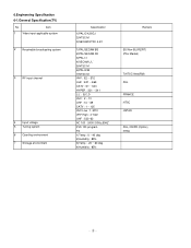
Item 1 Video input applicable system 2 Receivable broadcasting system 3 RF input channel 4 Input voltage 5 Tuning system 6 Operting environment 7 Storage environment Specification 1)PAL-D/K,B/G,I 2)NTSC-M 3)SECAM NTSC 4.43' 1)PAL/SECAM BG 2)PAL/SECAM DK 3)PAL I/I 4)SECAM L/L' 5)NTSC M 6)PAL-N/M 7)NTSC M VHF :... 100 - 240V/ 50Hz,60HZ FVS 100 program FS 1)Temp : 0 ~ 40 deg 2)Humidity : 85% 3)Temp : -20 ~ 60 deg 4)Humidity : 85% Remark EU/Non-EU(RZ/RT) (PAL Market) 7)NTSC Area(RM) PAL FRANCE NTSC JAPAN PAL, 200PR.(Option) NTSC 6.Engineering Specification 6-1.General Specification(TV) No.
Item 1 Video input applicable system 2 Receivable broadcasting system 3 RF input channel 4 Input voltage 5 Tuning system 6 Operting environment 7 Storage environment Specification 1)PAL-D/K,B/G,I 2)NTSC-M 3)SECAM NTSC 4.43' 1)PAL/SECAM BG 2)PAL/SECAM DK 3)PAL I/I 4)SECAM L/L' 5)NTSC M 6)PAL-N/M 7)NTSC M VHF :... 100 - 240V/ 50Hz,60HZ FVS 100 program FS 1)Temp : 0 ~ 40 deg 2)Humidity : 85% 3)Temp : -20 ~ 60 deg 4)Humidity : 85% Remark EU/Non-EU(RZ/RT) (PAL Market) 7)NTSC Area(RM) PAL FRANCE NTSC JAPAN PAL, 200PR.(Option) NTSC 6.Engineering Specification 6-1.General Specification(TV) No.
Service Manual
Page 9
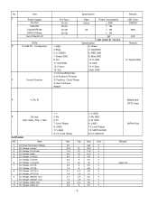
Item 1 Power Supply Normal Stand By Suspend Mode DPM Off Mode Cut-off Switch off ITEM 2 D-SUB Pin Configuraion 3 Control Function Specification H/V Sync On/On Off/On On/Off Off/Off - 1: RED 3: Blue: 5: S.T(GND) 7: Green GND 9: N.C 11: ID0(GND) 13: H-Sync 15: SCL 1) Contrast/Brightness 2) H-Position/V-Position 3) Tracking : Clock/ Phase 4) Auto Configure RESET Video Power Consumption Active 55W 1W Off 1W 1W - 0W PBP SWAP...
Item 1 Power Supply Normal Stand By Suspend Mode DPM Off Mode Cut-off Switch off ITEM 2 D-SUB Pin Configuraion 3 Control Function Specification H/V Sync On/On Off/On On/Off Off/Off - 1: RED 3: Blue: 5: S.T(GND) 7: Green GND 9: N.C 11: ID0(GND) 13: H-Sync 15: SCL 1) Contrast/Brightness 2) H-Position/V-Position 3) Tracking : Clock/ Phase 4) Auto Configure RESET Video Power Consumption Active 55W 1W Off 1W 1W - 0W PBP SWAP...

Service Manual
Page 10
...3 6-3. Video Input Level 2. Video Output Level 8. Video Input Level, R/G/B 15. Audio Input Frequency Response 4. Audio Output S/N 13. Video Input Level, Component(Y, PB, PR) 16. RGB Input Frame Rate 6-4. The Others NO Item 1 Search Sensitivity 2 Soft Ware Functionality Test 3 REMOCON Working Sensitivity, Straight 4 REMOCON Working Sensitivity, T/B/L/R 5 Closed Caption Sensitivity 6 Teletext Sensitivity 7. Signal Timing(Resolution) 7-1. Power NO Item 1. RGB Input Resolution, Vertical 17. Audio Output Level 11. Audio Input S/N 5. Audio Input Level 3. Audio Input...
...3 6-3. Video Input Level 2. Video Output Level 8. Video Input Level, R/G/B 15. Audio Input Frequency Response 4. Audio Output S/N 13. Video Input Level, Component(Y, PB, PR) 16. RGB Input Frame Rate 6-4. The Others NO Item 1 Search Sensitivity 2 Soft Ware Functionality Test 3 REMOCON Working Sensitivity, Straight 4 REMOCON Working Sensitivity, T/B/L/R 5 Closed Caption Sensitivity 6 Teletext Sensitivity 7. Signal Timing(Resolution) 7-1. Power NO Item 1. RGB Input Resolution, Vertical 17. Audio Output Level 11. Audio Input S/N 5. Audio Input Level 3. Audio Input...

Service Manual
Page 12
... Jack of Set to the adjustment mode using the factory automation equipment. Convert the input mode to PC input and convert to PC. Using the Pattern Generator (801GF, VG819) adjust WXGA (1280 X 768) for resolution and 16 Step Gray signals for the application to automatically adjust using the adjustment (SVC) remote controller and pressing the IN-START Key, and then press VOL+ Key at the Auto Gain menu. Set the input mode of LCD...
... Jack of Set to the adjustment mode using the factory automation equipment. Convert the input mode to PC input and convert to PC. Using the Pattern Generator (801GF, VG819) adjust WXGA (1280 X 768) for resolution and 16 Step Gray signals for the application to automatically adjust using the adjustment (SVC) remote controller and pressing the IN-START Key, and then press VOL+ Key at the Auto Gain menu. Set the input mode of LCD...

Service Manual
Page 14
... 1. EDID ADJUSTMENT Windows EDID V1.0 User Manual Operating System: MS Windows 98, 2000, XP Port Setup: Windows 98 => Don't need setup Windows 2000, XP => Need to LCD Monitor only. 2. This program is available to Port Setup. Cable Connection Port Setup a) Copy "UserPort.sys" file to "c:\WINNT\system32\drivers" folder b) Run Userport.exe c) Remove all default number d) Add 300-3FF 2) Edit Week of Manufacture, Year of Manufacture, Serial Number a) Input User Info Data b) Click "Update" button c) Click " Write" button e) Click Start button.
... 1. EDID ADJUSTMENT Windows EDID V1.0 User Manual Operating System: MS Windows 98, 2000, XP Port Setup: Windows 98 => Don't need setup Windows 2000, XP => Need to LCD Monitor only. 2. This program is available to Port Setup. Cable Connection Port Setup a) Copy "UserPort.sys" file to "c:\WINNT\system32\drivers" folder b) Run Userport.exe c) Remove all default number d) Add 300-3FF 2) Edit Week of Manufacture, Year of Manufacture, Serial Number a) Input User Info Data b) Click "Update" button c) Click " Write" button e) Click Start button.
Service Manual
Page 15
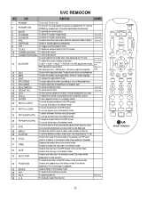
... INPUT(OP4) To use as video, voice, function or channel. To adjust the volume or accurately control a specific function. To set the delivery condition status after manufacturing the TV set a specific function or complete setting. Shortcut keys To check TV screen sound easily To select size of the PIP screen in the normal mode 34 POSITION Used as the update key in the teletext mode To select the simultaneous screen To adjust screen tilt To manually select...
... INPUT(OP4) To use as video, voice, function or channel. To adjust the volume or accurately control a specific function. To set the delivery condition status after manufacturing the TV set a specific function or complete setting. Shortcut keys To check TV screen sound easily To select size of the PIP screen in the normal mode 34 POSITION Used as the update key in the teletext mode To select the simultaneous screen To adjust screen tilt To manually select...

Service Manual
Page 17
No Raster :[B]Process Check LED Status on display unit Fail Repeat A PROCESS Check L900,L901 L902,L903 Fail Pass Check the input/ Output of IC901 Fail Pass Check inverter Connector or inverter Fail Pass Check panel link Cable or module Fail Pass Check input source cable and jack Fail Change L900,L901, L902,L903 Change IC901 Change inverter connector or inverter Change panel link cable or module Change module
No Raster :[B]Process Check LED Status on display unit Fail Repeat A PROCESS Check L900,L901 L902,L903 Fail Pass Check the input/ Output of IC901 Fail Pass Check inverter Connector or inverter Fail Pass Check panel link Cable or module Fail Pass Check input source cable and jack Fail Change L900,L901, L902,L903 Change IC901 Change inverter connector or inverter Change panel link cable or module Change module

Service Manual
Page 18
No Raster on Component signal Repeat [A] Process Pass Check the signal of L1200, L1202, L1203 Fail Pass Check the input/ output of IC1 Fail Check the input/output of IC800, IC851 Fail Pass Check the input/ output of IC901 Fail Pass Check input source cable and jack Check JA1200 or RCA CABLE Re-soldering or Change the defect part, Check X11 Re-soldering or Change the defect part Re-soldering or Change the defect part, Check X900
No Raster on Component signal Repeat [A] Process Pass Check the signal of L1200, L1202, L1203 Fail Pass Check the input/ output of IC1 Fail Check the input/output of IC800, IC851 Fail Pass Check the input/ output of IC901 Fail Pass Check input source cable and jack Check JA1200 or RCA CABLE Re-soldering or Change the defect part, Check X11 Re-soldering or Change the defect part Re-soldering or Change the defect part, Check X900
Service Manual
Page 19
No Raster on AV Signal (Video, S-Video) No Raster on TV(RF) signal Repeat [A] Process Pass Check the output of Fail TU1000 Check 5V, 33V of TU1000 Re-soldering or Fail Change the defect part Check the signal of L1209, L1210, L1212 Fail Change L1209, L1210, L1212 Pass Check the input/output of IC1 Pass Re-soldering or Change the defect part Fail Chek X11 Check the input/output of IC800, IC851 Pass Check the input/output of IC901 Pass Re-soldering or Fail Change the defect part Re-soldering or Change the defect part Fail Check X900 Check input source cable and jack
No Raster on AV Signal (Video, S-Video) No Raster on TV(RF) signal Repeat [A] Process Pass Check the output of Fail TU1000 Check 5V, 33V of TU1000 Re-soldering or Fail Change the defect part Check the signal of L1209, L1210, L1212 Fail Change L1209, L1210, L1212 Pass Check the input/output of IC1 Pass Re-soldering or Change the defect part Fail Chek X11 Check the input/output of IC800, IC851 Pass Check the input/output of IC901 Pass Re-soldering or Fail Change the defect part Re-soldering or Change the defect part Fail Check X900 Check input source cable and jack

Service Manual
Page 20
No Sound Check the input source Pass Change source input Fail Re-soldering or Check the input/output Change the defect part of IC1 Fail Check X11 Pass Check the input/output Re-soldering or of IC100,IC101 Fail Change the defect part Pass Check the speaker Pass Check the speaker wire Change speaker Fail
No Sound Check the input source Pass Change source input Fail Re-soldering or Check the input/output Change the defect part of IC1 Fail Check X11 Pass Check the input/output Re-soldering or of IC100,IC101 Fail Change the defect part Pass Check the speaker Pass Check the speaker wire Change speaker Fail

Service Manual
Page 21
SIDE_L,R SIDE V AC IN SCART R,G,B SCART V,L,R COMPONENT L,R Y Pb Pr H/P S-VHS V 14066 IC202 D-SUB Tuner TU1000 PC L,R AUDIO PC BLOCK DIAGRAM ML-041B Block Diagram ANALOG SIGNAL DIGITAL SIGNAL SOUND INPUT IF +,- INPUT SOUND OUTPUT POWER SIDE_AV IC100 IC101 Audio Amp L, R TC90A65F IC500 SM5301BS IC800 GM2221 IC901 TTL 1 OUT TTL 2 OUT LVDS1 OUT AT49F IC905 AT24C16 IC4 RGB OUT VCTI IC1 PC RGB M52758FP IC851 Z1000 S A W LA7222 IC2 IF+,-
SIDE_L,R SIDE V AC IN SCART R,G,B SCART V,L,R COMPONENT L,R Y Pb Pr H/P S-VHS V 14066 IC202 D-SUB Tuner TU1000 PC L,R AUDIO PC BLOCK DIAGRAM ML-041B Block Diagram ANALOG SIGNAL DIGITAL SIGNAL SOUND INPUT IF +,- INPUT SOUND OUTPUT POWER SIDE_AV IC100 IC101 Audio Amp L, R TC90A65F IC500 SM5301BS IC800 GM2221 IC901 TTL 1 OUT TTL 2 OUT LVDS1 OUT AT49F IC905 AT24C16 IC4 RGB OUT VCTI IC1 PC RGB M52758FP IC851 Z1000 S A W LA7222 IC2 IF+,-
Service Manual
Page 22
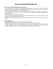
... the tuner, AV port (AV1, AV2, S-Video, component), and converts them into the LCD panel, and can control timing to an LVDS signal through the microcomputer (VCTI) combined with the video decoder that handles video signal processing and sound signal processing. BLOCK DIAGRAM DESCRIPTION 1. The scaler can also control the size and position of the input signal. 2. Or, it is the main microprocessor that integrates various functions in turn supplies electrical power...
... the tuner, AV port (AV1, AV2, S-Video, component), and converts them into the LCD panel, and can control timing to an LVDS signal through the microcomputer (VCTI) combined with the video decoder that handles video signal processing and sound signal processing. BLOCK DIAGRAM DESCRIPTION 1. The scaler can also control the size and position of the input signal. 2. Or, it is the main microprocessor that integrates various functions in turn supplies electrical power...
Service Manual
Page 25
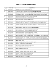
... 15LA70 COVER ASSEMBLY, RZ-15LA70 REAR A/V SCART ML041B BRACKET, REAR AV RZ-15LA70 ML024E HIPS . LCD(LIQUID CRYSTAL DISPLAY), M150X3-L04 XGA CHIMEI TFT COLOR LCD(LIQUID CRYSTAL DISPLAY), LC150X02-A4 LG PHILPS TFT COLOR TN,XGA,450NITS,8BITS LVDS LCD(LIQUID CRYSTAL DISPLAY), HT15X15-D01(A) BOE-HYDIS TFT COLOR XGA, TN 400NITS 25MS 4 CCFL, A-GRADE BACK COVER ASSEMBLY, RZ-15LA70 1SCART 3850VC0002F BACK COVER ASSEMBLY, RZ-15LA70 NON ML024E BRACKET ASSEMBLY, STAND RZ-15LA70 ML024E . BUTTON, CONTROL RZ-15LA70...
... 15LA70 COVER ASSEMBLY, RZ-15LA70 REAR A/V SCART ML041B BRACKET, REAR AV RZ-15LA70 ML024E HIPS . LCD(LIQUID CRYSTAL DISPLAY), M150X3-L04 XGA CHIMEI TFT COLOR LCD(LIQUID CRYSTAL DISPLAY), LC150X02-A4 LG PHILPS TFT COLOR TN,XGA,450NITS,8BITS LVDS LCD(LIQUID CRYSTAL DISPLAY), HT15X15-D01(A) BOE-HYDIS TFT COLOR XGA, TN 400NITS 25MS 4 CCFL, A-GRADE BACK COVER ASSEMBLY, RZ-15LA70 1SCART 3850VC0002F BACK COVER ASSEMBLY, RZ-15LA70 NON ML024E BRACKET ASSEMBLY, STAND RZ-15LA70 ML024E . BUTTON, CONTROL RZ-15LA70...


