
Service Manual
Page 2
... 4.1 Power ON Trouble 78 4.2 USB Trouble 79 4.3 SIM Detect Trouble 80 4.4 MicroSD card Trouble 81 4.5 Keypad And Touch key Trouble 82 4.6 Camera Trouble 85 4.7 Main LCD Trouble 89 4.8 Keypad Backlight Trouble 91 4.9 Folder ON/OFF Trouble 93 4.10 Audio Trouble Shooting 95 4.11 Charger Trouble Shooting 110 4.12 Checking Bluetooth Block... Checking Front End Module Block.....129 4.18 Checking Front End Module Block input logic 130 4.19 Checking WCDMA Block 133 4.20 Checking GSM Block 145 5. KU580 Download Setup Manual 157 6.
... 4.1 Power ON Trouble 78 4.2 USB Trouble 79 4.3 SIM Detect Trouble 80 4.4 MicroSD card Trouble 81 4.5 Keypad And Touch key Trouble 82 4.6 Camera Trouble 85 4.7 Main LCD Trouble 89 4.8 Keypad Backlight Trouble 91 4.9 Folder ON/OFF Trouble 93 4.10 Audio Trouble Shooting 95 4.11 Charger Trouble Shooting 110 4.12 Checking Bluetooth Block... Checking Front End Module Block.....129 4.18 Checking Front End Module Block input logic 130 4.19 Checking WCDMA Block 133 4.20 Checking GSM Block 145 5. KU580 Download Setup Manual 157 6.

Service Manual
Page 6
... Weight Power Talk Time Standby Time Antenna Main LCD Main LCD BL Vibrator MIC Receiver Earphone Jack SIM Socket Volume Key Voice Key External Memory I/O Connect Specification GSM900/1800/1900 & WCDMA Slide type - All right reserved. Inc. Flash Socket 18 Pin Copyright © 2007 LG Electronics. Dual Mode Handset 93.9X52.9X16.45...
... Weight Power Talk Time Standby Time Antenna Main LCD Main LCD BL Vibrator MIC Receiver Earphone Jack SIM Socket Volume Key Voice Key External Memory I/O Connect Specification GSM900/1800/1900 & WCDMA Slide type - All right reserved. Inc. Flash Socket 18 Pin Copyright © 2007 LG Electronics. Dual Mode Handset 93.9X52.9X16.45...
Service Manual
Page 15
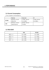
All right reserved. PERFORMANCE 2.4 Current Consumption (VT test : Speaker off, LCD backlight On) WCDMA GSM Stand by 280 Hours = 3.0 mA (DRX=2.56) 280 Hours = 3.0 mA (paging=5period) Voice Call 170 Min = 300 mA (Tx=12dBm) 200 ... -106 ± 2 dBm WCDMA -87 ± 2 dBm -97 ± 2 dBm -107 ± 2 dBm -112 ± 2 dBm LGE Internal Use Only - 16 - Inc. 2. Copyright © 2007 LG Electronics. Only for training and service purposes
All right reserved. PERFORMANCE 2.4 Current Consumption (VT test : Speaker off, LCD backlight On) WCDMA GSM Stand by 280 Hours = 3.0 mA (DRX=2.56) 280 Hours = 3.0 mA (paging=5period) Voice Call 170 Min = 300 mA (Tx=12dBm) 200 ... -106 ± 2 dBm WCDMA -87 ± 2 dBm -97 ± 2 dBm -107 ± 2 dBm -112 ± 2 dBm LGE Internal Use Only - 16 - Inc. 2. Copyright © 2007 LG Electronics. Only for training and service purposes

Service Manual
Page 44
... 2 19 3 18 4 17 5 16 6 15 7 14 8 13 9 12 10 11 CI_RES_n APP_I2C_SCL APP_I2C_SDA CI_HSYNC CI_VSYNC CI_D7 CI_D6 Figure 3-2-5. Main to LCD FPCB Connector(70Pin - VGA LCD FPCB Connector Copyright © 2007 LG Electronics. Inc. 3. Only for training and service purposes - 45 - All right reserved. LGE Internal Use Only Technical Brief VCAM_2V8 VCAM_1V8 VBAT...
... 2 19 3 18 4 17 5 16 6 15 7 14 8 13 9 12 10 11 CI_RES_n APP_I2C_SCL APP_I2C_SDA CI_HSYNC CI_VSYNC CI_D7 CI_D6 Figure 3-2-5. Main to LCD FPCB Connector(70Pin - VGA LCD FPCB Connector Copyright © 2007 LG Electronics. Inc. 3. Only for training and service purposes - 45 - All right reserved. LGE Internal Use Only Technical Brief VCAM_2V8 VCAM_1V8 VBAT...

Service Manual
Page 45
... port supply 24MHz master clock to Board connector. The camera module is dedicated camera interface port in Main) Table 3-2-2. Inc. Copyright © 2007 LG Electronics. Only for output RESET STANDBY GND 1.5V 2.8V 2.8V GND Master Input clock Hertical sync. Its interface is controlled by I2C port. All... right reserved. Technical Brief The 2M Camera modules are connected to 24-pin main board and VGA Camera module is connected to LCD FPCB with 20-pin Board to Board through 70 pin Board to camera module and receive 32.2MHz pixel clock(15fps), vertical sync ...
... port supply 24MHz master clock to Board connector. The camera module is dedicated camera interface port in Main) Table 3-2-2. Inc. Copyright © 2007 LG Electronics. Only for output RESET STANDBY GND 1.5V 2.8V 2.8V GND Master Input clock Hertical sync. Its interface is controlled by I2C port. All... right reserved. Technical Brief The 2M Camera modules are connected to 24-pin main board and VGA Camera module is connected to LCD FPCB with 20-pin Board to Board through 70 pin Board to camera module and receive 32.2MHz pixel clock(15fps), vertical sync ...

Service Manual
Page 46
... VDDF_2V5 VDDG_2V85 VDDK_2V75 VBACKUP to Hall Switch, AB3000 BEAR and Headph MICRON 1.8V, SS 1.5V to DB3100 analog to SD Card and LCD to Bluetooth to AB3000 RTC module VBUCK_FB VCORE to All I /O, digital) VBAT APP_GP10_BL_CTRL APP_GP03_CAM_LDO_CTRL ESD9X5.0ST5G INSTPAR ZD101 C102 10u U101 1... 1% 6.8K R122 1% 10K Figure 3-2-6. 1.8V and 2.8V Camera Regulator in AB3000 G4 ADSTR B9 ADOUT C8 VDDADC Copyright © 2007 LG Electronics. LGE Internal Use Only It's derived from AB3000 and controlled by camera driver file. Inc. All right reserved. Technical Brief 3.2.4 Camera...
... VDDF_2V5 VDDG_2V85 VDDK_2V75 VBACKUP to Hall Switch, AB3000 BEAR and Headph MICRON 1.8V, SS 1.5V to DB3100 analog to SD Card and LCD to Bluetooth to AB3000 RTC module VBUCK_FB VCORE to All I /O, digital) VBAT APP_GP10_BL_CTRL APP_GP03_CAM_LDO_CTRL ESD9X5.0ST5G INSTPAR ZD101 C102 10u U101 1... 1% 6.8K R122 1% 10K Figure 3-2-6. 1.8V and 2.8V Camera Regulator in AB3000 G4 ADSTR B9 ADOUT C8 VDDADC Copyright © 2007 LG Electronics. LGE Internal Use Only It's derived from AB3000 and controlled by camera driver file. Inc. All right reserved. Technical Brief 3.2.4 Camera...

Service Manual
Page 47
... 40-pin Connector in sub PCB. Only for training and service purposes Device in LCD Module LCD Module is controlled by 8bit PDI(Parallel Data Interface) in table 3-2 Device Main LCD Main LCD Backlight Type 320 x RGB x 240 262K Color TFT LCD 4 White LEDs Table 3-2-3. Signal 1 GND 2 LED C1 3 LED C4 4 LED A 5 GND 6 RESET... 33 D14 34 GND 35 GND 36 IF(IM) 37 GND 38 LED C3 39 LED C2 40 GND Table 3-2-4. Copyright © 2007 LG Electronics. Inc. All right reserved. Interface between LCD module and SUB PCB LGE Internal Use Only - 48 - Technical Brief 3.2.5 Display...
... 40-pin Connector in sub PCB. Only for training and service purposes Device in LCD Module LCD Module is controlled by 8bit PDI(Parallel Data Interface) in table 3-2 Device Main LCD Main LCD Backlight Type 320 x RGB x 240 262K Color TFT LCD 4 White LEDs Table 3-2-3. Signal 1 GND 2 LED C1 3 LED C4 4 LED A 5 GND 6 RESET... 33 D14 34 GND 35 GND 36 IF(IM) 37 GND 38 LED C3 39 LED C2 40 GND Table 3-2-4. Copyright © 2007 LG Electronics. Inc. All right reserved. Interface between LCD module and SUB PCB LGE Internal Use Only - 48 - Technical Brief 3.2.5 Display...
Service Manual
Page 48
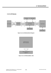
LCD Module(Main LCD) Copyright © 2007 LG Electronics. Only for training and service purposes - 49 - LCD Module Block Diagram 2M Camera 262K TFT LCD 320 X 240 pixels Main LCD Driver IC S6D0171 Figure 3-2-9. All right reserved. Technical Brief 3.2.6 LCD Module Vibrator Ear Piece LCD Module 40 pin Connector SUBPCB 40pin BtoB Connector LCD FPCB 70pin BtoB Connector Main Board VGA Camera Figure 3-2-8. Inc. LGE Internal Use Only 3.
LCD Module(Main LCD) Copyright © 2007 LG Electronics. Only for training and service purposes - 49 - LCD Module Block Diagram 2M Camera 262K TFT LCD 320 X 240 pixels Main LCD Driver IC S6D0171 Figure 3-2-9. All right reserved. Technical Brief 3.2.6 LCD Module Vibrator Ear Piece LCD Module 40 pin Connector SUBPCB 40pin BtoB Connector LCD FPCB 70pin BtoB Connector Main Board VGA Camera Figure 3-2-8. Inc. LGE Internal Use Only 3.
Service Manual
Page 49
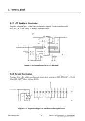
...Keypad Backlight LED Interface and Backlight Circuit LGE Internal Use Only - 50 - 3. Technical Brief 3.2.7 LCD Backlight Illumination There are driven by Charge Pump(MAX8631). Charge Pump Circuit LCD Backlight 3.2.8 Keypad Illumination There are 12 red LEDs in Main board backlight circuit, which are 4 ...white LEDs in LCD Backlight circuit which is used for training and service purposes APP_GP10_BL_CTRL...
...Keypad Backlight LED Interface and Backlight Circuit LGE Internal Use Only - 50 - 3. Technical Brief 3.2.7 LCD Backlight Illumination There are driven by Charge Pump(MAX8631). Charge Pump Circuit LCD Backlight 3.2.8 Keypad Illumination There are 12 red LEDs in Main board backlight circuit, which are 4 ...white LEDs in LCD Backlight circuit which is used for training and service purposes APP_GP10_BL_CTRL...
Service Manual
Page 54
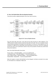
... B. Voice call Uplink Scheme From the audio path view point, voice call . Inc. Copyright © 2007 LG Electronics. Only for the listener at the other party, in 8 kHz mono, since this is displayed on Main LCD. 3. Receiver Mode : C-MIC(SP0102BE3) → Veronica Input(MIC1N/1P) Loud Speaker Mode : C-MIC(SP0102BE3) → Veronica...
... B. Voice call Uplink Scheme From the audio path view point, voice call . Inc. Copyright © 2007 LG Electronics. Only for the listener at the other party, in 8 kHz mono, since this is displayed on Main LCD. 3. Receiver Mode : C-MIC(SP0102BE3) → Veronica Input(MIC1N/1P) Loud Speaker Mode : C-MIC(SP0102BE3) → Veronica...
Service Manual
Page 86
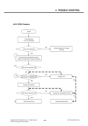
... training and service purposes - 87 - YES VGA Camera Works Follow the Power On Trouble Shooting Change U101 NO Change the Camera&LCD FPCB NO Change the Main Board Copyright © 2007 LG Electronics. NO NO 2 Pin4 of U101 or C109(sub)=1.8V? Inc. Pin5 of U101 or C108(sub)=2.8V? TROUBLE SHOOTING...
... training and service purposes - 87 - YES VGA Camera Works Follow the Power On Trouble Shooting Change U101 NO Change the Camera&LCD FPCB NO Change the Main Board Copyright © 2007 LG Electronics. NO NO 2 Pin4 of U101 or C109(sub)=1.8V? Inc. Pin5 of U101 or C108(sub)=2.8V? TROUBLE SHOOTING...

Service Manual
Page 87
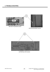
Inc. All right reserved. 4. Copyright © 2007 LG Electronics. TROUBLE SHOOTING CN5C0N1501 Main Board 70 pin BtoB Connector 1 CN101 LCD FPCB 20 pin VGA Connector 2 C109 C108 U101 Charge Pump in Sub Board LGE Internal Use Only - 88 - Only for training and service purposes
Inc. All right reserved. 4. Copyright © 2007 LG Electronics. TROUBLE SHOOTING CN5C0N1501 Main Board 70 pin BtoB Connector 1 CN101 LCD FPCB 20 pin VGA Connector 2 C109 C108 U101 Charge Pump in Sub Board LGE Internal Use Only - 88 - Only for training and service purposes
Service Manual
Page 88
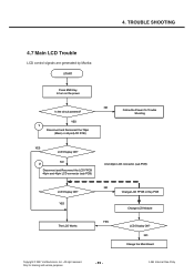
... on the power Is the circuit powered? LGE Internal Use Only NO Change the Main Board Copyright © 2007 LG Electronics. YES The LCD Works NO Change LCD FPCB or Key PCB YES Change LCD Module LCD Display OK? NO Follow the Power On Trouble Shooting YES 1 Disconnect and Reconnect the 70pin (Main) or 40...
... on the power Is the circuit powered? LGE Internal Use Only NO Change the Main Board Copyright © 2007 LG Electronics. YES The LCD Works NO Change LCD FPCB or Key PCB YES Change LCD Module LCD Display OK? NO Follow the Power On Trouble Shooting YES 1 Disconnect and Reconnect the 70pin (Main) or 40...
Service Manual
Page 89
Inc. Only for training and service purposes All right reserved. TROUBLE SHOOTING 1 CNC5N05101 Main Board 70 pin BtoB Connector LCD FPCB 40 pin BtoB Connector 2 sub PCB 40 pin LCD Connector LGE Internal Use Only - 90 - Copyright © 2007 LG Electronics. 4.
Inc. Only for training and service purposes All right reserved. TROUBLE SHOOTING 1 CNC5N05101 Main Board 70 pin BtoB Connector LCD FPCB 40 pin BtoB Connector 2 sub PCB 40 pin LCD Connector LGE Internal Use Only - 90 - Copyright © 2007 LG Electronics. 4.

Service Manual
Page 94
Copyright © 2007 LG Electronics. Only for training and service purposes - 95 - Speaker/Receiver ♣ Note : It is recommended that engineer should check the soldering of R, L, C along the corresponding path before every step. All right reserved. 4. Receiver • Signals to the receiver - LCD FPCB → 4. Receiver path : 1.Veronica (BEARP, BEARN)→ 2. R629,R631 on main board → 3. Receiver signals are generated atVeronica • BEARP, BEARN - Inc. LGE Internal Use Only TROUBLE SHOOTING 4.10 Audio Trouble Shooting 4.10.1.
Copyright © 2007 LG Electronics. Only for training and service purposes - 95 - Speaker/Receiver ♣ Note : It is recommended that engineer should check the soldering of R, L, C along the corresponding path before every step. All right reserved. 4. Receiver • Signals to the receiver - LCD FPCB → 4. Receiver path : 1.Veronica (BEARP, BEARN)→ 2. R629,R631 on main board → 3. Receiver signals are generated atVeronica • BEARP, BEARN - Inc. LGE Internal Use Only TROUBLE SHOOTING 4.10 Audio Trouble Shooting 4.10.1.
Service Manual
Page 95
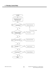
... main Bíd CN501? The sine wave not appear NO Check 629.631 YES Does the sine wave appear NO 3 at Number 67, 69 pin in LCD FPCB? Inc. All right reserved. Only for training and service purposes TROUBLE SHOOTING START Connect the phone to network Equipment and setup call Setup 1KHz... tone out NO 1 Does the sine wave appear at ZD500,ZD501 ? YES Can you hear sine wave out of the receiver ? 4. Copyright © 2007 LG Electronics. YES END NO Resolder Receiver NO Change the Receiver LGE Internal Use Only - 96 -
... main Bíd CN501? The sine wave not appear NO Check 629.631 YES Does the sine wave appear NO 3 at Number 67, 69 pin in LCD FPCB? Inc. All right reserved. Only for training and service purposes TROUBLE SHOOTING START Connect the phone to network Equipment and setup call Setup 1KHz... tone out NO 1 Does the sine wave appear at ZD500,ZD501 ? YES Can you hear sine wave out of the receiver ? 4. Copyright © 2007 LG Electronics. YES END NO Resolder Receiver NO Change the Receiver LGE Internal Use Only - 96 -

Service Manual
Page 96
Only for training and service purposes - 97 - TROUBLE SHOOTING A SIDE CN501 2 Pin 67, 69 1 ZD500,ZD501 LCD FPCB 3 Copyright © 2007 LG Electronics. All right reserved. 4. LGE Internal Use Only Inc.
Only for training and service purposes - 97 - TROUBLE SHOOTING A SIDE CN501 2 Pin 67, 69 1 ZD500,ZD501 LCD FPCB 3 Copyright © 2007 LG Electronics. All right reserved. 4. LGE Internal Use Only Inc.
Service Manual
Page 106
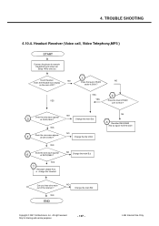
... appear 3 at R679,R680 ? YES Does the sine wave appear 5 at C641,C642 ? YES YES YES 2 Does the level of R429 NO on the main LCD? YES 7 Resolder CN400 Pins or change the Headset NO Change the main B,d NO Change the the U604 NO Change the main B,d N0 4 Resolder R603,R605... Connect the phone to network Equipment and setup call Setup 1KHz tone out 1 Insert Headset. YES END NO Change the main Bíd Copyright © 2007 LG Electronics.
... appear 3 at R679,R680 ? YES Does the sine wave appear 5 at C641,C642 ? YES YES YES 2 Does the level of R429 NO on the main LCD? YES 7 Resolder CN400 Pins or change the Headset NO Change the main B,d NO Change the the U604 NO Change the main B,d N0 4 Resolder R603,R605... Connect the phone to network Equipment and setup call Setup 1KHz tone out 1 Insert Headset. YES END NO Change the main Bíd Copyright © 2007 LG Electronics.
Service Manual
Page 107
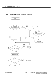
YES 5 Check the signal level at C426 at C426 ? NO Does the Headset icon display on the main LCD? YES Change the main B'd 9 NO Resolder C426 and try again from the start A few hundred of mV 8 of the signal measured at the putting Audio ... for training and service purposes TROUBLE SHOOTING 4.10.5. YES YES 2 Does the level of R627 NO under 0.5Volt ? All right reserved. Inc. Copyright © 2007 LG Electronics. 4.
YES 5 Check the signal level at C426 at C426 ? NO Does the Headset icon display on the main LCD? YES Change the main B'd 9 NO Resolder C426 and try again from the start A few hundred of mV 8 of the signal measured at the putting Audio ... for training and service purposes TROUBLE SHOOTING 4.10.5. YES YES 2 Does the level of R627 NO under 0.5Volt ? All right reserved. Inc. Copyright © 2007 LG Electronics. 4.

Service Manual
Page 171
... FB601 C645 2.2u H C647 2.2u 1 2 3 4 5 6 7 8 9 10 11 12 LGMC LGE Internal Use Only - 172 - Inc. Copyright © 2007 LG Electronics. 7. LDOs to RF3000, RF3100 analog and WCDMA Power Detector VDDD_1V5 to AB3000 CODECs/ADC/PLL R606 1% 0 VDDE_1V8 to All I/O Supplies and Memory R607 1% 0 VDIGRAD_1V8... VDD_C B12 VDD_H A9 VDD_F A7 VDD_G VDDH_CAM_CORE VDDF_2V5 VDDG_2V85 MICRON 1.8V, SS 1.5V to DB3100 analog to SD Card and LCD M12 VDD_K VDDK_2V75 to Bluetooth J11 VDDLP R609 VBACKUP to AB3000 RTC module BAT600 2.2K C607 C608 C609 C610 C611 C612 1u ...
... FB601 C645 2.2u H C647 2.2u 1 2 3 4 5 6 7 8 9 10 11 12 LGMC LGE Internal Use Only - 172 - Inc. Copyright © 2007 LG Electronics. 7. LDOs to RF3000, RF3100 analog and WCDMA Power Detector VDDD_1V5 to AB3000 CODECs/ADC/PLL R606 1% 0 VDDE_1V8 to All I/O Supplies and Memory R607 1% 0 VDIGRAD_1V8... VDD_C B12 VDD_H A9 VDD_F A7 VDD_G VDDH_CAM_CORE VDDF_2V5 VDDG_2V85 MICRON 1.8V, SS 1.5V to DB3100 analog to SD Card and LCD M12 VDD_K VDDK_2V75 to Bluetooth J11 VDDLP R609 VBACKUP to AB3000 RTC module BAT600 2.2K C607 C608 C609 C610 C611 C612 1u ...


