Owner's Manual
Page 1
OWNER'S MANUAL PLASMA TV Please read this manual carefully before operating your set and retain it for future reference. 42PT200 50PT200 42PT350 50PT350 60PV250 50PV400 60PV400 50PV450 60PV450 42PT250U 50PT250U 50PV550U 60PV550U 42PT350C 50PT350C 50PV450C 60PV450C P/NO : SAC34173308 (1109-REV04) www.lg.com
OWNER'S MANUAL PLASMA TV Please read this manual carefully before operating your set and retain it for future reference. 42PT200 50PT200 42PT350 50PT350 60PV250 50PV400 60PV400 50PV450 60PV450 42PT250U 50PT250U 50PV550U 60PV550U 42PT350C 50PT350C 50PV450C 60PV450C P/NO : SAC34173308 (1109-REV04) www.lg.com

Owner's Manual
Page 4
... the risk of your appliance, and if its appearance indicates damage or deterioration, unplug it to prevent possible electric shock (i.e. Do not install this owner's manual to plugs, wall outlets, and the point where the cord exits the appliance. Short-circuit Breaker Power Supply 18 DISCONNECTING DEVICE FROM MAINS Mains plug...
... the risk of your appliance, and if its appearance indicates damage or deterioration, unplug it to prevent possible electric shock (i.e. Do not install this owner's manual to plugs, wall outlets, and the point where the cord exits the appliance. Short-circuit Breaker Power Supply 18 DISCONNECTING DEVICE FROM MAINS Mains plug...
Owner's Manual
Page 6
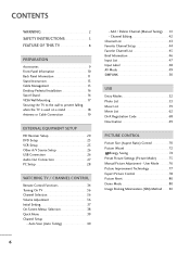
Auto Scan (Auto Tuning 40 - Add / Delete Channel (Manual Tuning 41 - User Mode 76 Picture Improvement Technology 77 Expert Picture Control 78 Picture Reset 80 Demo Mode 80 Image Sticking Minimization (ISM) Method ... Registration Code 68 Deactivation 69 PICTURE CONTROL Picture Size (Aspect Ratio) Control 70 Picture Wizard 72 Energy Saving 74 Preset Picture Settings (Picture Mode 75 Manual Picture Adjustment - CONTENTS WARNING 2 SAFETY INSTRUCTIONS 3 FEATURE OF THIS TV 8 PREPARATION Accessories 9 Front Panel Information 10 Back Panel Information 11 Stand Instruction 13...
Auto Scan (Auto Tuning 40 - Add / Delete Channel (Manual Tuning 41 - User Mode 76 Picture Improvement Technology 77 Expert Picture Control 78 Picture Reset 80 Demo Mode 80 Image Sticking Minimization (ISM) Method ... Registration Code 68 Deactivation 69 PICTURE CONTROL Picture Size (Aspect Ratio) Control 70 Picture Wizard 72 Energy Saving 74 Preset Picture Settings (Picture Mode 75 Manual Picture Adjustment - CONTENTS WARNING 2 SAFETY INSTRUCTIONS 3 FEATURE OF THIS TV 8 PREPARATION Accessories 9 Front Panel Information 10 Back Panel Information 11 Stand Instruction 13...

Owner's Manual
Page 7
... Setup 88 Audio Reset 89 Stereo/SAP Broadcast Setup 90 Audio Language 91 On-Screen Menus Language Selection 92 Caption Mode - Auto Clock Setup 96 Manual Clock Setup 97 Auto On/Off Time Setting 98 Sleep Timer Setting 99 Auto Shut-Off Setting 99 PARENTAL CONTROL / RATINGS Set Password & Lock System...
... Setup 88 Audio Reset 89 Stereo/SAP Broadcast Setup 90 Audio Language 91 On-Screen Menus Language Selection 92 Caption Mode - Auto Clock Setup 96 Manual Clock Setup 97 Auto On/Off Time Setting 98 Sleep Timer Setting 99 Auto Shut-Off Setting 99 PARENTAL CONTROL / RATINGS Set Password & Lock System...

Owner's Manual
Page 9
... and 2. - If there are included with your TV. Wind the PC audio cable on the ferrite core once. PREPARATION Owner's Manual CD Manual (For 42/50PT200, 42/50PT350, 42/50PT350C, 42/50PT250U, 50PV400, 50PV450, 50PV450C, 50PV550U) Protection Cover and Tape (Refer to P.14)... (For 60PV250, 60PV400, 60PV450, 60PV450C, 60PV550U) Power Cord Ferrite Core (Depending on model) x 4 x 3 x 4 x 3 1.5V 1.5V Power Cord Holder M4x26 M5x14.5 Screws ...
... and 2. - If there are included with your TV. Wind the PC audio cable on the ferrite core once. PREPARATION Owner's Manual CD Manual (For 42/50PT200, 42/50PT350, 42/50PT350C, 42/50PT250U, 50PV400, 50PV450, 50PV450C, 50PV550U) Protection Cover and Tape (Refer to P.14)... (For 60PV250, 60PV400, 60PV450, 60PV450C, 60PV550U) Power Cord Ferrite Core (Depending on model) x 4 x 3 x 4 x 3 1.5V 1.5V Power Cord Holder M4x26 M5x14.5 Screws ...
Owner's Manual
Page 16
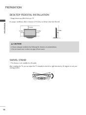
After installing the TV, you can adjust the TV manually to suit your TV. PREPARATION PREPARATION DESKTOP PEDESTAL INSTALLATION I This feature is not available for all four sides from your viewing position. 16 G Do not mount near or above any type of 4 inches on all models. SWIVEL STAND I Image shown may differ from the wall. 4 inches 4 inches 4 inches 4 inches CAUTION G Ensure adequate ventilation by 20 degrees to the left or right direction by following the clearance recommendations. For proper ventilation, allow a clearance of heat source.
After installing the TV, you can adjust the TV manually to suit your TV. PREPARATION PREPARATION DESKTOP PEDESTAL INSTALLATION I This feature is not available for all four sides from your viewing position. 16 G Do not mount near or above any type of 4 inches on all models. SWIVEL STAND I Image shown may differ from the wall. 4 inches 4 inches 4 inches 4 inches CAUTION G Ensure adequate ventilation by 20 degrees to the left or right direction by following the clearance recommendations. For proper ventilation, allow a clearance of heat source.

Owner's Manual
Page 17
...sold separately) 42/50PT200, 42/50PT350, 42/50PT350C, 50PV400, PSW400B, 50PV450, 400 * 400 M6 4 PSW400BG 50PV450C, 42/50PT250U, 50PV550U 60PV250, 60PV400, 60PV450, 60PV450C, 60PV550U 600 * 400 M8 4 PSW600B, PSW600BG ! For further information, refer to other building materials, please contact your TV is ...screw specifications, the length of accidents. G When purchasing our wall mount kit, a detailed installation manual and all parts necessary for wall mount kits are provided. LG is not liable for TV damage or personal injury when a non-VESA or non specified wall ...
...sold separately) 42/50PT200, 42/50PT350, 42/50PT350C, 50PV400, PSW400B, 50PV450, 400 * 400 M6 4 PSW400BG 50PV450C, 42/50PT250U, 50PV550U 60PV250, 60PV400, 60PV450, 60PV450C, 60PV550U 600 * 400 M8 4 PSW600B, PSW600BG ! For further information, refer to other building materials, please contact your TV is ...screw specifications, the length of accidents. G When purchasing our wall mount kit, a detailed installation manual and all parts necessary for wall mount kits are provided. LG is not liable for TV damage or personal injury when a non-VESA or non specified wall ...
Owner's Manual
Page 20
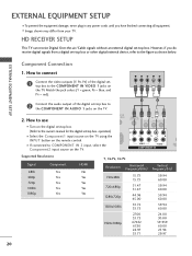
... AUDIO 1 jacks on the TV. How to use I Turn on the digital set -top box. EXTERNAL EQUIPMENT SETUP Component Connection 1. I If connected to the owner's manual for the digital set -top box. (Refer to COMPONENT IN 2 input, select the Component2 input source on the TV. 1 2 2. I Image shown may differ from a digital...
... AUDIO 1 jacks on the TV. How to use I Turn on the digital set -top box. EXTERNAL EQUIPMENT SETUP Component Connection 1. I If connected to the owner's manual for the digital set -top box. (Refer to COMPONENT IN 2 input, select the Component2 input source on the TV. 1 2 2. I Image shown may differ from a digital...
Owner's Manual
Page 21
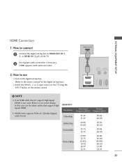
... (CONTROL & SERVICE) RGB IN(PC) ! How to connect 1 Connect the digital set -top box.) I Turn on the digital set-top box. (Refer to the owner's manual for the digital set -top box to use the latest cables that support High Speed HDMI.
... (CONTROL & SERVICE) RGB IN(PC) ! How to connect 1 Connect the digital set -top box.) I Turn on the digital set-top box. (Refer to the owner's manual for the digital set -top box to use the latest cables that support High Speed HDMI.
Owner's Manual
Page 22
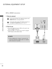
NOTE G A DVI to the owner's manual for this connection. DVI doesn't support audio, so a separate audio connection is required for the digital set-top box.) I Turn on the digital set -top ...
NOTE G A DVI to the owner's manual for this connection. DVI doesn't support audio, so a separate audio connection is required for the digital set-top box.) I Turn on the digital set -top ...
Owner's Manual
Page 23
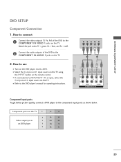
... PB PR B-Y R-Y Cb Cr Pb Pr 23 I Refer to use I If connected to the component input ports as shown below. How to the DVD player's manual for operating instructions. I Turn on the TV. DIO IN B/DVI) REMOTE CONTROL IN AV IN 1 VIDEO /MONO AUDIO 2 L R 1 VIDEO AUDIO A COMPONENT IN Component Input ports...
... PB PR B-Y R-Y Cb Cr Pb Pr 23 I Refer to use I If connected to the component input ports as shown below. How to the DVD player's manual for operating instructions. I Turn on the TV. DIO IN B/DVI) REMOTE CONTROL IN AV IN 1 VIDEO /MONO AUDIO 2 L R 1 VIDEO AUDIO A COMPONENT IN Component Input ports...
Owner's Manual
Page 24
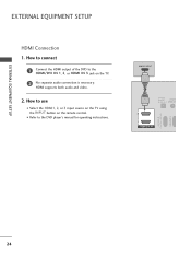
How to use I Refer to the HDMI/DVI IN 1, 2, or HDMI IN 3 jack on the remote control. I Select the HDMI1, 2, or 3 input source on the TV using the INPUT button on the TV. 2 No separate audio connection is necessary. HDMI-DTV OUTPUT 1 OPTICAL DIGITAL AUDIO AUDIO OUT (RGB/DV 2 1 HDMI/DVI IN RS-232C IN (CONTROL & SERVICE) RGB IN(PC) 24 EXTERNAL EQUIPMENT SETUP EXTERNAL EQUIPMENT SETUP HDMI Connection 1. HDMI supports both audio and video. 2. How to connect 1 Connect the HDMI output of the DVD to the DVD player's manual for operating instructions.
How to use I Refer to the HDMI/DVI IN 1, 2, or HDMI IN 3 jack on the remote control. I Select the HDMI1, 2, or 3 input source on the TV using the INPUT button on the TV. 2 No separate audio connection is necessary. HDMI-DTV OUTPUT 1 OPTICAL DIGITAL AUDIO AUDIO OUT (RGB/DV 2 1 HDMI/DVI IN RS-232C IN (CONTROL & SERVICE) RGB IN(PC) 24 EXTERNAL EQUIPMENT SETUP EXTERNAL EQUIPMENT SETUP HDMI Connection 1. HDMI supports both audio and video. 2. How to connect 1 Connect the HDMI output of the DVD to the DVD player's manual for operating instructions.

Owner's Manual
Page 25
How to use I Set VCR output switch to 3 or 4 and then tune TV to the VCR owner's manual.) I Insert a video tape into the VCR and press PLAY on the VCR. (Refer to the ANTENNA/CABLE IN socket on the TV. ! Match the jack ... AV IN 2, select AV2 input source on the TV. How to connect 1 Connect the RF antenna out socket of the VCR to the VCR owner's manual.) ANT OUT S-VIDEO VIDEO L R ANT IN OUTPUT SWITCH 2 Wall Jack Antenna Composite (RCA) Connection 1. I If connected to the AUDIO L/MONO jack of the VCR. 2. How...
How to use I Set VCR output switch to 3 or 4 and then tune TV to the VCR owner's manual.) I Insert a video tape into the VCR and press PLAY on the VCR. (Refer to the ANTENNA/CABLE IN socket on the TV. ! Match the jack ... AV IN 2, select AV2 input source on the TV. How to connect 1 Connect the RF antenna out socket of the VCR to the VCR owner's manual.) ANT OUT S-VIDEO VIDEO L R ANT IN OUTPUT SWITCH 2 Wall Jack Antenna Composite (RCA) Connection 1. I If connected to the AUDIO L/MONO jack of the VCR. 2. How...
Owner's Manual
Page 27
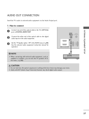
... audio equipment, such as amplifiers or speakers, you can turn the TV speakers off in the AUDIO menu. (G p.88) See the external audio equipment instruction manual for operation. How to connect 1 Connect one end of the optical cable to the TV's OPTICAL port of DIGITAL AUDIO OUT. 2 Connect the other end...
... audio equipment, such as amplifiers or speakers, you can turn the TV speakers off in the AUDIO menu. (G p.88) See the external audio equipment instruction manual for operation. How to connect 1 Connect one end of the optical cable to the TV's OPTICAL port of DIGITAL AUDIO OUT. 2 Connect the other end...

Owner's Manual
Page 31
...) Enter G Screen Resolution Auto config. To Set Yes No 1 Home 2 ENTER Select PICTURE. After adjustment, if the image is still not correct, try using the manual settings or a different resolution or refresh rate on the PC.
...) Enter G Screen Resolution Auto config. To Set Yes No 1 Home 2 ENTER Select PICTURE. After adjustment, if the image is still not correct, try using the manual settings or a different resolution or refresh rate on the PC.

Owner's Manual
Page 32
... 2 ENTER 3 ENTER 4 ENTER 5 ENTER Select PICTURE. I S i z e: This function is not clear after auto adjustment and especially if characters are still trembling, adjust the picture phase manually. Move D Position G F Size E Phase Reset Prev. Select Screen (RGB-PC). I Position: This function is to adjust picture to left/right and up/down as you...
... 2 ENTER 3 ENTER 4 ENTER 5 ENTER Select PICTURE. I S i z e: This function is not clear after auto adjustment and especially if characters are still trembling, adjust the picture phase manually. Move D Position G F Size E Phase Reset Prev. Select Screen (RGB-PC). I Position: This function is to adjust picture to left/right and up/down as you...

Owner's Manual
Page 37
... Year Month Date Hour Minute Time Zone Daylight Saving F Auto G 2007 11 15 5 PM 52 Eastern Auto Previous Next 1 Select A ut o or Manual. 2 ENTER Select desired time option. The previous channel information will be displayed on the screen when turning the TV on until the Initial setting procedure... is only intended for choosing LG Next Step2. It can also adjust Initial Setting in -store mode after 5 minutes. Picture mode" manually while inspecting the TV, but the TV will appear whenever the TV is "Home Use". ...
... Year Month Date Hour Minute Time Zone Daylight Saving F Auto G 2007 11 15 5 PM 52 Eastern Auto Previous Next 1 Select A ut o or Manual. 2 ENTER Select desired time option. The previous channel information will be displayed on the screen when turning the TV on until the Initial setting procedure... is only intended for choosing LG Next Step2. It can also adjust Initial Setting in -store mode after 5 minutes. Picture mode" manually while inspecting the TV, but the TV will appear whenever the TV is "Home Use". ...

Owner's Manual
Page 38
... TV / CHANNEL CONTROL ON-SCREEN MENUS SELECTION Your TV's OSD (On Screen Display) may differ slightly from that shown in this manual. Except 42/50PT250U, 50/60PV550U CHANNEL Auto Tuning Manual Tuning Channel Edit Move Enter PICTURE Move Aspect Ratio : 16:9 Picture Wizard Energy Saving : Off Picture Mode : Standard • Contrast 90...
... TV / CHANNEL CONTROL ON-SCREEN MENUS SELECTION Your TV's OSD (On Screen Display) may differ slightly from that shown in this manual. Except 42/50PT250U, 50/60PV550U CHANNEL Auto Tuning Manual Tuning Channel Edit Move Enter PICTURE Move Aspect Ratio : 16:9 Picture Wizard Energy Saving : Off Picture Mode : Standard • Contrast 90...

Owner's Manual
Page 39
... your desired picture format. Make appropriate adjustments. 3 EXIT Return to the Favorite List. Caption: Select on the viewing environment. Eject USB: Select "Eject" in this manual. WATCHING TV / CHANNEL CONTROL QUICK MENU Your TV's OSD (On Screen Display) may differ slightly from what is a menu of features which users might use...
... your desired picture format. Make appropriate adjustments. 3 EXIT Return to the Favorite List. Caption: Select on the viewing environment. Eject USB: Select "Eject" in this manual. WATCHING TV / CHANNEL CONTROL QUICK MENU Your TV's OSD (On Screen Display) may differ slightly from what is a menu of features which users might use...

Owner's Manual
Page 40
... function with the antenna connected during Auto Tuning. Auto Tuning memorizes only the channels available at the time. I When setting the Auto tuning or Manual tuning, the number of DTV, TV, CADTV, and CATV. 40 Select Y e s. 4 ENTER Run Auto Tuning. 5 BACK Return to ...Tuning) Automatically finds all the available channels in memory on the broadcasting signal environment. CHANNEL Auto Tuning Manual Tuning Channel Edit Move Enter CHANNEL Auto Tuning Manual Tuning Channel Edit Move Enter Check your residence or move the TV. The previous channel information will ask...
... function with the antenna connected during Auto Tuning. Auto Tuning memorizes only the channels available at the time. I When setting the Auto tuning or Manual tuning, the number of DTV, TV, CADTV, and CATV. 40 Select Y e s. 4 ENTER Run Auto Tuning. 5 BACK Return to ...Tuning) Automatically finds all the available channels in memory on the broadcasting signal environment. CHANNEL Auto Tuning Manual Tuning Channel Edit Move Enter CHANNEL Auto Tuning Manual Tuning Channel Edit Move Enter Check your residence or move the TV. The previous channel information will ask...


