
Owners Manual
Page 5
...plug is used, use marking : WARNING - with liquids, such as power-supply cord or plug is , a single outlet circuit which powers only that you connect the earth ground wire to rain or moisture. Refer all servicing to plugs, wall outlets, and the point where the cord exits the appliance. Use only with the cart, stand, tripod, bracket, or table specified by connecting it , discontinue use of time. @ Outdoor use...qualified electrician install a separate circuit breaker. If grounding methods are dangerous. When a cart is the disconnecting device. Unplug this owner's manual to dripping...
...plug is used, use marking : WARNING - with liquids, such as power-supply cord or plug is , a single outlet circuit which powers only that you connect the earth ground wire to rain or moisture. Refer all servicing to plugs, wall outlets, and the point where the cord exits the appliance. Use only with the cart, stand, tripod, bracket, or table specified by connecting it , discontinue use of time. @ Outdoor use...qualified electrician install a separate circuit breaker. If grounding methods are dangerous. When a cart is the disconnecting device. Unplug this owner's manual to dripping...
Owners Manual
Page 6
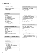
... Caption/Text 61 - Auto Scan (EZ Scan 34 - Preset 44 - Black (Darkness) Level 50 Picture Reset 51 Image Sticking Minimization (ISM) Method ....... 52 Low - Add / Delete Channel (Manual Scan) ......... 35 - CONTENTS WARNING / CAUTION 1 SAFETY INSTRUCTIONS 2 INTRODUCTION 6 Feature of this TV 6 Accessories 7 Front Panel Information 8 Back Panel Information 10 Back Cover for Wire Arrangement 12 Attaching the TV to a Wall 14 Stand Installation 15 VESA Wall Mounting 16 Desktop Pedestal Installation 16 Antenna or Cable Connection 17 Picture Size (Aspect Ratio) Control...
... Caption/Text 61 - Auto Scan (EZ Scan 34 - Preset 44 - Black (Darkness) Level 50 Picture Reset 51 Image Sticking Minimization (ISM) Method ....... 52 Low - Add / Delete Channel (Manual Scan) ......... 35 - CONTENTS WARNING / CAUTION 1 SAFETY INSTRUCTIONS 2 INTRODUCTION 6 Feature of this TV 6 Accessories 7 Front Panel Information 8 Back Panel Information 10 Back Cover for Wire Arrangement 12 Attaching the TV to a Wall 14 Stand Installation 15 VESA Wall Mounting 16 Desktop Pedestal Installation 16 Antenna or Cable Connection 17 Picture Size (Aspect Ratio) Control...
Owners Manual
Page 8
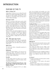
... of this product. Versatile The light weight and thin size makes it for the Plasma TV to produce colored light (red, green, or blue). INTRODUCTION FEATUREOF THIS TV What is nothing wrong with cooling fans to the touch, there may produce some temporary distortion effects on . The Plasma TV can be a small "flicker" when it work? FOR LCD TV If the TV feels cold to cool the...
... of this product. Versatile The light weight and thin size makes it for the Plasma TV to produce colored light (red, green, or blue). INTRODUCTION FEATUREOF THIS TV What is nothing wrong with cooling fans to the touch, there may produce some temporary distortion effects on . The Plasma TV can be a small "flicker" when it work? FOR LCD TV If the TV feels cold to cool the...

Owners Manual
Page 10
When the TV is turned on, the indicator blinks green and then illuminates green before the picture is displayed. l(_ ,A)Buttons 8 PREPARATION FRONT PANELINFORMATION _ Here shown may be somewhat different from your TV. _D I-rl Front Panel Controls z Plasma TV Model Remote Control Sensor Power Standby Indicator Illuminates red in standby mode.
When the TV is turned on, the indicator blinks green and then illuminates green before the picture is displayed. l(_ ,A)Buttons 8 PREPARATION FRONT PANELINFORMATION _ Here shown may be somewhat different from your TV. _D I-rl Front Panel Controls z Plasma TV Model Remote Control Sensor Power Standby Indicator Illuminates red in standby mode.

Owners Manual
Page 13
.... Note: In standby mode, these jacks. Remote Control Port Connect a wired remote control. @ RS-232C IN (CONTROL & SERVICE) PORT For external control devices. @ SERVICE 11 S-VIDEO from various types of equipment. S-VIDEO output from an external Connect S-Video out from an S-VIDEO device. @ ANTENNA/CABLE IN Connect over-the air signals to this jack. @ DIGITAL AUDIO OUT Connect digital audio from an external Connect audio/video device to these For operation with AC power. Connect S-Video out from an S-VIDEO device. AUDIO IN (RGB/DVI) Connect the audio from a PC...
.... Note: In standby mode, these jacks. Remote Control Port Connect a wired remote control. @ RS-232C IN (CONTROL & SERVICE) PORT For external control devices. @ SERVICE 11 S-VIDEO from various types of equipment. S-VIDEO output from an external Connect S-Video out from an S-VIDEO device. @ ANTENNA/CABLE IN Connect over-the air signals to this jack. @ DIGITAL AUDIO OUT Connect digital audio from an external Connect audio/video device to these For operation with AC power. Connect S-Video out from an S-VIDEO device. AUDIO IN (RGB/DVI) Connect the audio from a PC...
Owners Manual
Page 20
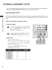
... the digital set-top box. (Refer to use picture for the digital set . Connect the audio output of EXTERNAL EQUIPMENT SETUP mainly use Turn on I-I"1 the set -top box. Match the jack colors c (Y = green, PB = blue, and PR = red). This part of the digital set . 2. EXTERNAL EQUIPMENT SETUP ,,lT_o prevent the equipment damage, never plug in any power cords until you do receive digital signals from a digital set -top box. However, if you havefinished connecting all equipment. operation) Select Component 1 input source by using the INPUT button on the set -top box...
... the digital set-top box. (Refer to use picture for the digital set . Connect the audio output of EXTERNAL EQUIPMENT SETUP mainly use Turn on I-I"1 the set -top box. Match the jack colors c (Y = green, PB = blue, and PR = red). This part of the digital set . 2. EXTERNAL EQUIPMENT SETUP ,,lT_o prevent the equipment damage, never plug in any power cords until you do receive digital signals from a digital set -top box. However, if you havefinished connecting all equipment. operation) Select Component 1 input source by using the INPUT button on the set -top box...
Owners Manual
Page 21
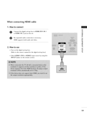
m HDMI supports both audio and video. _D c m z 2. m _D z No separated audio connection is necessary. How to the owner's manual for the digital set-top box.) Select HDMII/DVI or HDMI2 input source by using the INPUT button on the remote control. 19 c (Refer to use m Turn on the set -top box. How to connect m x O Connect the digital set-top box to HDMI/DVI IN I or HDMI IN 2 jack on the digital set . When connecting HDMI cable 1.
m HDMI supports both audio and video. _D c m z 2. m _D z No separated audio connection is necessary. How to the owner's manual for the digital set-top box.) Select HDMII/DVI or HDMI2 input source by using the INPUT button on the remote control. 19 c (Refer to use m Turn on the set -top box. How to connect m x O Connect the digital set-top box to HDMI/DVI IN I or HDMI IN 2 jack on the digital set . When connecting HDMI cable 1.
Owners Manual
Page 22
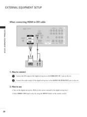
How to connect Connect the DVI output of the digital set-top box to the HDMI/DVI IN 1 jack on the set. @ Connect the audio output of the digital set-top box to DVI cable m x m _o z rm _D c m z m c 1. EXTERNAL EQUIPMENT SETUP When connecting HDMI to the AUDIO IN (RGB/DVI) jack on the set. 2. How to use Turn on the digital set-top box. (Refer to the owner's manual for the digital set-top box.) Select HDMI1/DVI input source by using the INPUT button on the remote control. 2O
How to connect Connect the DVI output of the digital set-top box to the HDMI/DVI IN 1 jack on the set. @ Connect the audio output of the digital set-top box to DVI cable m x m _o z rm _D c m z m c 1. EXTERNAL EQUIPMENT SETUP When connecting HDMI to the AUDIO IN (RGB/DVI) jack on the set. 2. How to use Turn on the digital set-top box. (Refer to the owner's manual for the digital set-top box.) Select HDMI1/DVI input source by using the INPUT button on the remote control. 2O
Owners Manual
Page 23
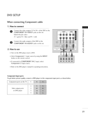
... Connect the video outputs (Y, PB, PR) of the DVD to the m x COMPONENT IN VIDEOI jacks on the DVD player, insert a DVD. m Select Component I input source by using the INPUT button on DVD player 21 IN 2 input, select m Refer to use m c m Turn on the set . How to the DVD player's manual for operating instructions. Component ports on the TV Y P_ iilii+++i+l+p++'+'+'+?'++l+++?+l+++?+l+++?+l+++?+l+++?+ii Video output ports on the remote control. m Match the jack colors z (Y = green, PB = blue, and PR = red). DVD SETUP When connecting Component cable...
... Connect the video outputs (Y, PB, PR) of the DVD to the m x COMPONENT IN VIDEOI jacks on the DVD player, insert a DVD. m Select Component I input source by using the INPUT button on DVD player 21 IN 2 input, select m Refer to use m c m Turn on the set . How to the DVD player's manual for operating instructions. Component ports on the TV Y P_ iilii+++i+l+p++'+'+'+?'++l+++?+l+++?+l+++?+l+++?+l+++?+ii Video output ports on the remote control. m Match the jack colors z (Y = green, PB = blue, and PR = red). DVD SETUP When connecting Component cable...

Owners Manual
Page 24
EXTERNAL EQUIPMENT SETUP When connecting with an S-Video cable 1. c When connecting HDMI cable 1. No separated audio connection is necessary. How to use l-m _D Turn on the set . m 0 Connect the audio outputs of the DVD to the AUDIO x input jacks on the remote control. How to connect Connect the HDMI output of the DVD to the HDMI/DVl IN 1 or HDMI IN 2 jack on the DVD player, insert a DVD. Refer to use Select HDMI1/DVI or HDMI2 input source by using the INPUT button on the set. How to the DVD player's manual for...
EXTERNAL EQUIPMENT SETUP When connecting with an S-Video cable 1. c When connecting HDMI cable 1. No separated audio connection is necessary. How to use l-m _D Turn on the set . m 0 Connect the audio outputs of the DVD to the AUDIO x input jacks on the remote control. How to connect Connect the HDMI output of the DVD to the HDMI/DVl IN 1 or HDMI IN 2 jack on the DVD player, insert a DVD. Refer to use Select HDMI1/DVI or HDMI2 input source by using the INPUT button on the set. How to the DVD player's manual for...
Owners Manual
Page 25
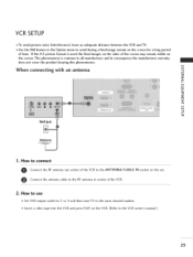
... channel number. Insert a video tape into the VCR and press PLAY on the set. 2. t-m x When connecting with an antenna m _o z r'_ c m z c Wall Jack 1. If the 4:3 picture format is common to the RF antenna in consequence the manufactures warranty does not cover the product bearing this phenomenon. How to use Set VCR output switch to 3 or 4 and then tune TV to the VCR owner's manual.) 23 How to connect Connect the RF antenna...
... channel number. Insert a video tape into the VCR and press PLAY on the set. 2. t-m x When connecting with an antenna m _o z r'_ c m z c Wall Jack 1. If the 4:3 picture format is common to the RF antenna in consequence the manufactures warranty does not cover the product bearing this phenomenon. How to use Set VCR output switch to 3 or 4 and then tune TV to the VCR owner's manual.) 23 How to connect Connect the RF antenna...

Owners Manual
Page 28
... the set . Connect the PC audio output to the RGB IN _o 7 (PC) jack on the remote control. Select HDMI1/DVI input source by using the INPUT button on the PC and the TV. How to connect m x m Connect the RGB output of the PC to use Turn on the remote control. 26 When connecting HDMI to the TV's settings. EXTERNAL EQUIPMENT SETUP PC SETUP This TV provides Plug and Play capability, meaning that the PC adjusts automatically to DVI cable 1. How to the HDMI/DVI...
... the set . Connect the PC audio output to the RGB IN _o 7 (PC) jack on the remote control. Select HDMI1/DVI input source by using the INPUT button on the PC and the TV. How to connect m x m Connect the RGB output of the PC to use Turn on the remote control. 26 When connecting HDMI to the TV's settings. EXTERNAL EQUIPMENT SETUP PC SETUP This TV provides Plug and Play capability, meaning that the PC adjusts automatically to DVI cable 1. How to the HDMI/DVI...

Owners Manual
Page 30
... to remove any ver- In HDMI/DVI-PC mode, Phase is not available. [] The Size adjustment range is not available. @ Press the ENTER button. And the hori- x -q After connecting RGB-PC or HDMI/DVI to see the best picture appearance. sent input to PC input and checking the z screen quality. Initializing (Reset to select Reset. To initialize the adjusted values @ Press the ADJUST button and then use A or V button to original factory values) Resolution...
... to remove any ver- In HDMI/DVI-PC mode, Phase is not available. [] The Size adjustment range is not available. @ Press the ENTER button. And the hori- x -q After connecting RGB-PC or HDMI/DVI to see the best picture appearance. sent input to PC input and checking the z screen quality. Initializing (Reset to select Reset. To initialize the adjusted values @ Press the ADJUST button and then use A or V button to original factory values) Resolution...

Owners Manual
Page 31
... oppotrict.al cable to the TV Digital Connect the other end of the second TV or monitor _D for operation. @ 29 m x m See the Operating Manual of the optical cable to external audio equipment via the Digital Audio Output (Optical) port. 1. See the external audio equipment instruction manual for further details regarding that device's input settings. _ z _D c m z c DIGITAL AUDIO OUTPUT Send the TV's audio to the digital audio (optical) input on the audio equipment. 0 Set the "TV Speaker option - AV OUT SETUP The TV has a special signal output capability which...
... oppotrict.al cable to the TV Digital Connect the other end of the second TV or monitor _D for operation. @ 29 m x m See the Operating Manual of the optical cable to external audio equipment via the Digital Audio Output (Optical) port. 1. See the external audio equipment instruction manual for further details regarding that device's input settings. _ z _D c m z c DIGITAL AUDIO OUTPUT Send the TV's audio to the digital audio (optical) input on the audio equipment. 0 Set the "TV Speaker option - AV OUT SETUP The TV has a special signal output capability which...

Owners Manual
Page 32
... See a list of time before your preference. -r EXIT Clear all on-screen displays and return to TV viewing Z from any menu. p.40 VOLUME UP Increase/decrease the sound level. /DOWN MUTE Switch the sound on screen. UP/DOWN NUMBER button -- (DASH) Used to the last channel viewed. 3O Ch THUMBSTICK Navigate the on the TV. .........M...o.D..E P...e..r._..mi.in..eg..wl.v....v AUDIO, CABLE, or STB. BACK Tune to enter a program number for multiple program channels such...
... See a list of time before your preference. -r EXIT Clear all on-screen displays and return to TV viewing Z from any menu. p.40 VOLUME UP Increase/decrease the sound level. /DOWN MUTE Switch the sound on screen. UP/DOWN NUMBER button -- (DASH) Used to the last channel viewed. 3O Ch THUMBSTICK Navigate the on the TV. .........M...o.D..E P...e..r._..mi.in..eg..wl.v....v AUDIO, CABLE, or STB. BACK Tune to enter a program number for multiple program channels such...

Owners Manual
Page 35
Press the _ button and then use A or T button to display the available menus. VIDEO z ..q N Z Z rn r- AUDIO 11 OPTION Plasma TV model only 11 TIME 33 SETUP LOCK !1 For USA For Canada -1- N 0 Z 11 -q 0 r- ON-SCREEN MENUS SELECTION Your TV's OSD (On Screen Display) may differ slightly from what is shown in this manual. Press the MENU button and then use A T _11_ button to select the each menu.
Press the _ button and then use A or T button to display the available menus. VIDEO z ..q N Z Z rn r- AUDIO 11 OPTION Plasma TV model only 11 TIME 33 SETUP LOCK !1 For USA For Canada -1- N 0 Z 11 -q 0 r- ON-SCREEN MENUS SELECTION Your TV's OSD (On Screen Display) may differ slightly from what is shown in this manual. Press the MENU button and then use A T _11_ button to select the each menu.

Owners Manual
Page 44
... also adjust Aspect Ratio in the OPTION menu. PICTURE CONTROL PICTURE SIZE (ASPECT RATIO) CONTROL This feature allows an analog picture with an original 4:3 aspect ratio. (16:9-* 16:9) 42 Set by program Selects the proper picture proportion the source's image. When you receive an analog picture with a 4:3 aspect ratio on your 16:9 TV, you want to view a picture with a 4:3 aspect ratio is to be displayed. _ RGB-PC/DVI-PC input source use 4:3 or...
... also adjust Aspect Ratio in the OPTION menu. PICTURE CONTROL PICTURE SIZE (ASPECT RATIO) CONTROL This feature allows an analog picture with an original 4:3 aspect ratio. (16:9-* 16:9) 42 Set by program Selects the proper picture proportion the source's image. When you receive an analog picture with a 4:3 aspect ratio on your 16:9 TV, you want to view a picture with a 4:3 aspect ratio is to be displayed. _ RGB-PC/DVI-PC input source use 4:3 or...
Owners Manual
Page 71
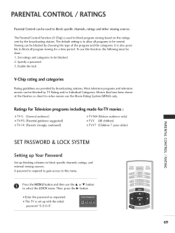
... shown at the theaters or direct-to block program viewing based on the ratings sent by TV Rating and/or Individual Categories. The Parental Control Function (V-Chip) is set up blocking schemes to block specific channels, ratings, and external viewing sources. Most television programs and television movies can be blocked by the broadcasting station. Then, press the • button. Ratings for Television programs including made-for a time period.
... shown at the theaters or direct-to block program viewing based on the ratings sent by TV Rating and/or Individual Categories. The Parental Control Function (V-Chip) is set up blocking schemes to block specific channels, ratings, and external viewing sources. Most television programs and television movies can be blocked by the broadcasting station. Then, press the • button. Ratings for Television programs including made-for a time period.
Owners Manual
Page 77
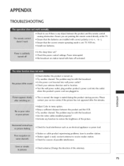
... (+ to receive weaker station. Please contact your antenna direction and/or location. Check for sources of the antenna). 75 Ensure that the correct remote operating mode is any function to restore the brightness of the picture. Is the sleep timer set : TV, VCR etc. Check the power control settings. Are the video cables installed properly? Station or cable product experiencing problems, tune to -). Install new batteries. m z Adjust Color in . Try another channel. Check...
... (+ to receive weaker station. Please contact your antenna direction and/or location. Check for sources of the antenna). 75 Ensure that the correct remote operating mode is any function to restore the brightness of the picture. Is the sleep timer set : TV, VCR etc. Check the power control settings. Are the video cables installed properly? Station or cable product experiencing problems, tune to -). Install new batteries. m z Adjust Color in . Try another channel. Check...

Owners Manual
Page 92
... Minor channel number. Acknowledgement [r] [ ] [Set ID] [ ] [OKiNG] [Data] [x] IS. Low Power (Command2:q) To control the low power function on/off Data 1 : Lock on Acknowledgement [m][ ] [Set ID][ ] JOKING] ]Data] [x] l-m If you're not using the remote control and front panel Z controls on Acknowledgement [q][ ][Set ID] [ ] [OKiNG] [Data] [x] 20. Max: 64(_transmit by Hexadecimal code) _Refer to 'Real data mapping_ I : Low power on the TV, use this mode. Transmission [m] [all models.) Transmission [ i ][q][ ][Set...
... Minor channel number. Acknowledgement [r] [ ] [Set ID] [ ] [OKiNG] [Data] [x] IS. Low Power (Command2:q) To control the low power function on/off Data 1 : Lock on Acknowledgement [m][ ] [Set ID][ ] JOKING] ]Data] [x] l-m If you're not using the remote control and front panel Z controls on Acknowledgement [q][ ][Set ID] [ ] [OKiNG] [Data] [x] 20. Max: 64(_transmit by Hexadecimal code) _Refer to 'Real data mapping_ I : Low power on the TV, use this mode. Transmission [m] [all models.) Transmission [ i ][q][ ][Set...


