
Owner's Manual (English)
Page 3
Wall Brackets 2-eye-bolts 2- INPUT D/A INPUT POWER SIMPLINK BRIGHT MODE TV VCR DVD RATIO TEXT INFO i GUIDE Owner's Manual 1.5V 1.5V Batteries MENU EXIT SUBTITLE MARK OK VOL Q.VIEW PR PAGE MUTE 1 2 3 4 5 6 7 8 9 LIST 0 FAV SIZE ? I /II TIME USB SLEEP Remote Control Power Cord Polishing Cloth This feature is not available for stand assembly Refer to p. 9 50PY3DF* only Additional Cover Refer to p. 16 3 - TV Bracket Bolts the twist holder. 2- Wall Brackets This feature is missing, please con- If an accessory...
Wall Brackets 2-eye-bolts 2- INPUT D/A INPUT POWER SIMPLINK BRIGHT MODE TV VCR DVD RATIO TEXT INFO i GUIDE Owner's Manual 1.5V 1.5V Batteries MENU EXIT SUBTITLE MARK OK VOL Q.VIEW PR PAGE MUTE 1 2 3 4 5 6 7 8 9 LIST 0 FAV SIZE ? I /II TIME USB SLEEP Remote Control Power Cord Polishing Cloth This feature is not available for stand assembly Refer to p. 9 50PY3DF* only Additional Cover Refer to p. 16 3 - TV Bracket Bolts the twist holder. 2- Wall Brackets This feature is missing, please con- If an accessory...
Owner's Manual (English)
Page 4
... GUIDE) Switch on/off EPG 62 Select a programme 62 Button Function in NOW/NEXT Guide Mode . 63 Button Function in 7 Days Guide Mode 63 Button Function in Extended Description Box . 64 Button Function in Reservation Setting Mode . 64 PICTURE CONTROL Picture Size (Aspect Ratio) Control 65 Preset Picture Settings - Picture Mode - Preset 66 - Screen Setup for Wire Arrangement 12 Desktop Pedestal Installation 15 Wall Mount: Horizontal Installation 15 Not Using The Desk-type Stand 16 Antenna Connection 17 EXTERNAL EQUIPMENT SETUP HD Receiver Setup 18 DVD Setup 21 VCR Setup...
... GUIDE) Switch on/off EPG 62 Select a programme 62 Button Function in NOW/NEXT Guide Mode . 63 Button Function in 7 Days Guide Mode 63 Button Function in Extended Description Box . 64 Button Function in Reservation Setting Mode . 64 PICTURE CONTROL Picture Size (Aspect Ratio) Control 65 Preset Picture Settings - Picture Mode - Preset 66 - Screen Setup for Wire Arrangement 12 Desktop Pedestal Installation 15 Wall Mount: Horizontal Installation 15 Not Using The Desk-type Stand 16 Antenna Connection 17 EXTERNAL EQUIPMENT SETUP HD Receiver Setup 18 DVD Setup 21 VCR Setup...

Owner's Manual (English)
Page 9
... (PC) AUDIO (RGB/DVI) COMPONENT IN 34 5 6 ANTENNA IN DIGITAL AUDIO OUT REMOTE CONTROL IN OPTICAL VIDEO RS-232C IN (CONTROL & SERVICE) AV OUT AUDIO AV IN 1 S-VIDEO VIDEO 7 AUDIO VIDEO (MONO) AUDIO 89 1 HDMI/DVI IN 7 COMPONENT IN Connect a HDMI signal. Note: In standby mode, these jacks. 8 AV (Audio/Video) IN 1 2 RGB/AUDIO IN Connect audio/video output from an external Connect the output from a set top box or PC to these ports do not work. 7 Connect a component video/audio device to the appropriate input port. device to operate the TV on a PC...
... (PC) AUDIO (RGB/DVI) COMPONENT IN 34 5 6 ANTENNA IN DIGITAL AUDIO OUT REMOTE CONTROL IN OPTICAL VIDEO RS-232C IN (CONTROL & SERVICE) AV OUT AUDIO AV IN 1 S-VIDEO VIDEO 7 AUDIO VIDEO (MONO) AUDIO 89 1 HDMI/DVI IN 7 COMPONENT IN Connect a HDMI signal. Note: In standby mode, these jacks. 8 AV (Audio/Video) IN 1 2 RGB/AUDIO IN Connect audio/video output from an external Connect the output from a set top box or PC to these ports do not work. 7 Connect a component video/audio device to the appropriate input port. device to operate the TV on a PC...

Owner's Manual (English)
Page 10
... audio/video output from an external Connect the output from various types of COMPONENT IN equipment. LCD TV Models 42/47/52LB9DF* USB IN S-VIDEO USB IN 32LB9D* USB IN S-VIDEO USB Input S-VIDEO Input Connect S-Video out from an S-VIDEO device. Connect a component video/audio device to these ports do not work. Never attemDIGpITtALto AUDIO OUT operate the TV on a PC. 9 AV OUT 4 Remote Control Port Connect a second TV or monitor. Connect your TV. S-VIDEO 3 RS-232C IN (CONTROL &SERVICE) PORT Connect S-Video out from an S-VIDEO device. Or DVI(VIDEO) signal...
... audio/video output from an external Connect the output from various types of COMPONENT IN equipment. LCD TV Models 42/47/52LB9DF* USB IN S-VIDEO USB IN 32LB9D* USB IN S-VIDEO USB Input S-VIDEO Input Connect S-Video out from an S-VIDEO device. Connect a component video/audio device to these ports do not work. Never attemDIGpITtALto AUDIO OUT operate the TV on a PC. 9 AV OUT 4 Remote Control Port Connect a second TV or monitor. Connect your TV. S-VIDEO 3 RS-232C IN (CONTROL &SERVICE) PORT Connect S-Video out from an S-VIDEO device. Or DVI(VIDEO) signal...
Owner's Manual (English)
Page 20
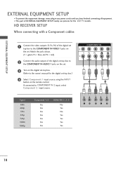
... plug in any power cords until you have finished connecting all equipment. If connected to the COMPONENT IN VIDEO 1 jacks on the set -top box.) 4 Select Component 1 input source using the INPUT button on the digital set-top box. (Refer to the owner's manual for the LCD TV models. EXTERNAL EQUIPMENT SETUP EXTERNAL EQUIPMENT SETUP I This part of EXTERNAL EQUIPMENT SETUP mainly use pictures for the digital set . Match the jack colours. (Y = green, PB = blue, and PR = red) 2 Connect the audio output of the digital set top box to COMPONENT IN 2 input...
... plug in any power cords until you have finished connecting all equipment. If connected to the COMPONENT IN VIDEO 1 jacks on the set -top box.) 4 Select Component 1 input source using the INPUT button on the digital set-top box. (Refer to the owner's manual for the LCD TV models. EXTERNAL EQUIPMENT SETUP EXTERNAL EQUIPMENT SETUP I This part of EXTERNAL EQUIPMENT SETUP mainly use pictures for the digital set . Match the jack colours. (Y = green, PB = blue, and PR = red) 2 Connect the audio output of the digital set top box to COMPONENT IN 2 input...

Owner's Manual (English)
Page 21
.... EXTERNAL EQUIPMENT SETUP AUDIO DIGITAL (RGB/DVI) AUDIO OUT When connecting with HDMI cable NENT IN 1 Connect the digital set-top box to HDMI/DVI IN1, 2 or 3 jack on the remote control. ! AUDIO 2 3 Turn on the digital set-top box. (Refer to 1920x1080i/1080p. (32LB9D*, 42/50PB4D*: 1280x720p) 1 HDMI-DTV OUTPUT 19 NOTE G If the digital set-top box supports Auto HDMI function, the output resolution of the source device to the owner's manual for the digital set-top box.) 1 COMPONENT IN VIDEO AUDIO 4 Select HDMI1, HDMI2 or HDMI3 input source using the INPUT button on...
.... EXTERNAL EQUIPMENT SETUP AUDIO DIGITAL (RGB/DVI) AUDIO OUT When connecting with HDMI cable NENT IN 1 Connect the digital set-top box to HDMI/DVI IN1, 2 or 3 jack on the remote control. ! AUDIO 2 3 Turn on the digital set-top box. (Refer to 1920x1080i/1080p. (32LB9D*, 42/50PB4D*: 1280x720p) 1 HDMI-DTV OUTPUT 19 NOTE G If the digital set-top box supports Auto HDMI function, the output resolution of the source device to the owner's manual for the digital set-top box.) 1 COMPONENT IN VIDEO AUDIO 4 Select HDMI1, HDMI2 or HDMI3 input source using the INPUT button on...

Owner's Manual (English)
Page 22
... REMOTE CONTROL IN DIGITAL AUDIO OUT OPTICAL VIDEO RS-232C IN (CONTROL & SERVICE) AUDIO VIDEO AUDIO S-VIDEO VIDEO (MONO) AUDIO 1 2 AV OUT AV IN 1 DVI-DTV OUTPUT L R 1 Connect the DVI output of the digital set-top box to the HDMI/DVI IN1, 2 or 3 jack on the set. 2 Connect the audio output of the digital set-top box to the AUDIO(RGB/DVI) jack on the set. 3 Turn on the digital set-top box. (Refer to the owner's manual for the digital set-top box.) 4 Select HDMI1, HDMI2 or HDMI3 input source with using the INPUT button on the remote control...
... REMOTE CONTROL IN DIGITAL AUDIO OUT OPTICAL VIDEO RS-232C IN (CONTROL & SERVICE) AUDIO VIDEO AUDIO S-VIDEO VIDEO (MONO) AUDIO 1 2 AV OUT AV IN 1 DVI-DTV OUTPUT L R 1 Connect the DVI output of the digital set-top box to the HDMI/DVI IN1, 2 or 3 jack on the set. 2 Connect the audio output of the digital set-top box to the AUDIO(RGB/DVI) jack on the set. 3 Turn on the digital set-top box. (Refer to the owner's manual for the digital set-top box.) 4 Select HDMI1, HDMI2 or HDMI3 input source with using the INPUT button on the remote control...

Owner's Manual (English)
Page 24
UO S-VIDEO VIDEO (MONO) AUDIO 1 2 When connecting HDMI cable S-VIDEO L R AUDIO 1 Connect the HDMI output of the DVD to the HDMI/DVI IN1, 2 or 3 jack on the set. 2 No separate audio connection is necessary. 3 Select HDMI1, HDMI2 or HDMI3 input source using the INPUT button on the remote control. 4 Refer to the DVD player's manual for operating instruc- G If the DVD does not support Auto HDMI, you need to set . VIDEO AUDIO 2 Connect the audio outputs of the DVD to the AUDIO input jacks on the set to 1280x720p. AV IN 1 EXTERNAL EQUIPMENT SETUP RGB...
UO S-VIDEO VIDEO (MONO) AUDIO 1 2 When connecting HDMI cable S-VIDEO L R AUDIO 1 Connect the HDMI output of the DVD to the HDMI/DVI IN1, 2 or 3 jack on the set. 2 No separate audio connection is necessary. 3 Select HDMI1, HDMI2 or HDMI3 input source using the INPUT button on the remote control. 4 Refer to the DVD player's manual for operating instruc- G If the DVD does not support Auto HDMI, you need to set . VIDEO AUDIO 2 Connect the audio outputs of the DVD to the AUDIO input jacks on the set to 1280x720p. AV IN 1 EXTERNAL EQUIPMENT SETUP RGB...

Owner's Manual (English)
Page 25
... is used; R HDMI/DVI IN RGB When connecting with an antenna C 2 EXTERNAL EQUIPMENT SETUP HDMI/DVI IN 2 1 (DVI) RGB IN RGB (PC) AUDIO (RGB/DVI) COMPONENT IN ANTENNA IN REMOTE CONTROL IN DIGITAL AUDIO OUT OPTICAL VIDEO RS-232C IN (CONTROL & SERVICE) AUDIO VIDEO AUDIO S-VIDEO VIDEO (MONO) AUDIO AV IN 1 AV OUT 1 ANT OUT S-VIDEO VIDEO L R ANT IN OUTPUT SWITCH 2 Wall Jack 1 (DVI) VI Antenna 1 Connect the RF antenna out socket of the VCR. 3 Set VCR output switch to 3 or 4 and then tune TV to the same programme number. 4 Insert a video...
... is used; R HDMI/DVI IN RGB When connecting with an antenna C 2 EXTERNAL EQUIPMENT SETUP HDMI/DVI IN 2 1 (DVI) RGB IN RGB (PC) AUDIO (RGB/DVI) COMPONENT IN ANTENNA IN REMOTE CONTROL IN DIGITAL AUDIO OUT OPTICAL VIDEO RS-232C IN (CONTROL & SERVICE) AUDIO VIDEO AUDIO S-VIDEO VIDEO (MONO) AUDIO AV IN 1 AV OUT 1 ANT OUT S-VIDEO VIDEO L R ANT IN OUTPUT SWITCH 2 Wall Jack 1 (DVI) VI Antenna 1 Connect the RF antenna out socket of the VCR. 3 Set VCR output switch to 3 or 4 and then tune TV to the same programme number. 4 Insert a video...

Owner's Manual (English)
Page 26
... 1 AUDIO S-VIDEO VIDEO (MONO) AUDIO 2 Connect the audio outputs of the set . HDMI/DVI IN RGB IN RGB (PC) EXTERNAL EQUIPMENT SETUP COMPONENT IN 2 When connecting with an S-Video cable 1 (DVI) VIDEO AUDIO 1 Connect the S-VIDEO output of the VCR to the VCR owner's manual.) 1 3 Select A V 1 input source using the INPUT button on the set. S-VIDEO VIDEO L R ANT IN OUTPUT ANT OUT SWITCH CAUTION G Do not connect to the VCR owner's manual.) 4 SeleCctOAMVPO1NinEpNuTtINsource using the INPUT button on the set . compared to the AUDIO input jacks on the remote control...
... 1 AUDIO S-VIDEO VIDEO (MONO) AUDIO 2 Connect the audio outputs of the set . HDMI/DVI IN RGB IN RGB (PC) EXTERNAL EQUIPMENT SETUP COMPONENT IN 2 When connecting with an S-Video cable 1 (DVI) VIDEO AUDIO 1 Connect the S-VIDEO output of the VCR to the VCR owner's manual.) 1 3 Select A V 1 input source using the INPUT button on the set. S-VIDEO VIDEO L R ANT IN OUTPUT ANT OUT SWITCH CAUTION G Do not connect to the VCR owner's manual.) 4 SeleCctOAMVPO1NinEpNuTtINsource using the INPUT button on the set . compared to the AUDIO input jacks on the remote control...

Owner's Manual (English)
Page 28
... REMOTE CONTROL IN DIGITAL AUDIO OUT OPTICA RS-232C IN (CONTROL & SERVICE) VIDEO AUDIO S-VIDEO VIDEO (MON 1 2 ! VIDEO 3AUDIOTurn on the PC graphic card. The TV perceives 1024x768, 60Hz as DTV 720p based on the PC and the set . COMPONENT IN 2 Connect the PC audio output to the AUDIO (RGB/DVI) jack on the VIDEO menu until the picture is present, change the PC output to the TV's settings. If noise is clear. EXTERNAL EQUIPMENT SETUP EXTERNAL EQUIPMENT SETUP PC SETUP This TV...
... REMOTE CONTROL IN DIGITAL AUDIO OUT OPTICA RS-232C IN (CONTROL & SERVICE) VIDEO AUDIO S-VIDEO VIDEO (MON 1 2 ! VIDEO 3AUDIOTurn on the PC graphic card. The TV perceives 1024x768, 60Hz as DTV 720p based on the PC and the set . COMPONENT IN 2 Connect the PC audio output to the AUDIO (RGB/DVI) jack on the VIDEO menu until the picture is present, change the PC output to the TV's settings. If noise is clear. EXTERNAL EQUIPMENT SETUP EXTERNAL EQUIPMENT SETUP PC SETUP This TV...
Owner's Manual (English)
Page 29
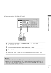
... best picture quality, adjust the PC graphics card's output resolution to 1920x1080, 60Hz. (42PB4D* : 1024x768p, 32LB9D*/50PB4D*: 1360x768p) 27 G If the PC does not support Auto DVI, you need to set . 4 Select HDMI1, HDMI2 or HDMI3 input source using the INPUT button on the remote control. ! AV OUT EXTERNAL EQUIPMENT SETUP When connecting HDMI to DVI cable HDMI/DVI IN 3 2 1 RGB IN RGB (PC) AUDIO (RGB/DVI) COMPONENT IN ANTENNA IN REMOTE CONTROL IN DIGITAL AUDIO OUT OPTICAL VIDEO RS-232C IN (CONTROL & SERVICE) AUDIO VIDEO AUDIO S-VIDEO VIDEO (MONO) AUDIO 1 2 AV IN 1 DVI...
... best picture quality, adjust the PC graphics card's output resolution to 1920x1080, 60Hz. (42PB4D* : 1024x768p, 32LB9D*/50PB4D*: 1360x768p) 27 G If the PC does not support Auto DVI, you need to set . 4 Select HDMI1, HDMI2 or HDMI3 input source using the INPUT button on the remote control. ! AV OUT EXTERNAL EQUIPMENT SETUP When connecting HDMI to DVI cable HDMI/DVI IN 3 2 1 RGB IN RGB (PC) AUDIO (RGB/DVI) COMPONENT IN ANTENNA IN REMOTE CONTROL IN DIGITAL AUDIO OUT OPTICAL VIDEO RS-232C IN (CONTROL & SERVICE) AUDIO VIDEO AUDIO S-VIDEO VIDEO (MONO) AUDIO 1 2 AV IN 1 DVI...

Owner's Manual (English)
Page 30
G Avoid keeping a fixed image on the screen. The fixed image may not work if a HDMI to DVI Cable is separate. G The synchronization input form for a long period of time. EXTERNAL EQUIPMENT SETUP EXTERNAL EQUIPMENT SETUP Supported Display Specifications (RGB/HDMI-PC) Resolution Horizontal Vertical Frequency(kHz) Frequency(Hz) 640x480 720x400 31.469 37.500 ...50.00 60.00 59.94 50.00 23.976 24.00 29.97 30.00 50.00 59.94 60.00 28 NOTES G Depending on the graphics card, DOS mode may become permanently imprinted on the screen for Horizontal and Vertical frequencies is in use...
G Avoid keeping a fixed image on the screen. The fixed image may not work if a HDMI to DVI Cable is separate. G The synchronization input form for a long period of time. EXTERNAL EQUIPMENT SETUP EXTERNAL EQUIPMENT SETUP Supported Display Specifications (RGB/HDMI-PC) Resolution Horizontal Vertical Frequency(kHz) Frequency(Hz) 640x480 720x400 31.469 37.500 ...50.00 60.00 59.94 50.00 23.976 24.00 29.97 30.00 50.00 59.94 60.00 28 NOTES G Depending on the graphics card, DOS mode may become permanently imprinted on the screen for Horizontal and Vertical frequencies is in use...

Owner's Manual (English)
Page 31
... you change the resolution, select the proper resolution in present input to see the best picture appearance. 1 Press the MENU button and then use D or E button to select the PICTURE menu. 2 Press the G button and then use D or E button to select Screen. 3 Press the G button to a PC Output, Select RGB-PC with using the INPUT button on the remote control. EXTERNAL EQUIPMENT SETUP Screen Setup for PC mode Overview When the RGB input, of the set is connected to enter the screen adjustment menu.
... you change the resolution, select the proper resolution in present input to see the best picture appearance. 1 Press the MENU button and then use D or E button to select the PICTURE menu. 2 Press the G button and then use D or E button to select Screen. 3 Press the G button to a PC Output, Select RGB-PC with using the INPUT button on the remote control. EXTERNAL EQUIPMENT SETUP Screen Setup for PC mode Overview When the RGB input, of the set is connected to enter the screen adjustment menu.

Owner's Manual (English)
Page 35
RGB IN HDMI/DVI IN 1 Connect one end of the optical cable to the digi- tal audio (optical) input on the audio equipment. 1 (DVI) VIDEO AUDIO 3 Set the "TV Speaker option - See the external audio equipment instruction manual for operation. AV OUT EXTERNAL EQUIPMENT SETUP AV IN 1 DIGITAL AUDIO OUTPUT SETUP Send the TV's audio to the TRGVB (DPCi)gital Audio (Optical) Output port. Off" in the AUDIO menu. Looking at the laser beam may damage your vision. 33 NOTE G When connecting with external audio equipments, such...
RGB IN HDMI/DVI IN 1 Connect one end of the optical cable to the digi- tal audio (optical) input on the audio equipment. 1 (DVI) VIDEO AUDIO 3 Set the "TV Speaker option - See the external audio equipment instruction manual for operation. AV OUT EXTERNAL EQUIPMENT SETUP AV IN 1 DIGITAL AUDIO OUTPUT SETUP Send the TV's audio to the TRGVB (DPCi)gital Audio (Optical) Output port. Off" in the AUDIO menu. Looking at the laser beam may damage your vision. 33 NOTE G When connecting with external audio equipments, such...

Owner's Manual (English)
Page 36
... INDEX I /II Selects the sound output or the audio mode. LIST Displays the programme table. USBD Remove the USB device. THUMBSTICK Adjusts menu settings. (Up/Down/Left Right) Selects menu item. PROGRAMME Select a programme. NUMBER button Selects a programme. POWER Switches the set of AV devices connected to the next one. VCR/DVD Control some video cassette recorders or DVD players control buttons ("RECORD" button is not available for DVD player). Control the mode control buttons mode. Selects numbered items in regular sequence: Digital, Analogue, AV1-2, Component...
... INDEX I /II Selects the sound output or the audio mode. LIST Displays the programme table. USBD Remove the USB device. THUMBSTICK Adjusts menu settings. (Up/Down/Left Right) Selects menu item. PROGRAMME Select a programme. NUMBER button Selects a programme. POWER Switches the set of AV devices connected to the next one. VCR/DVD Control some video cassette recorders or DVD players control buttons ("RECORD" button is not available for DVD player). Control the mode control buttons mode. Selects numbered items in regular sequence: Digital, Analogue, AV1-2, Component...
Owner's Manual (English)
Page 37
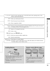
... TV viewing from any menu. Don't mix old or used to enable teletext services while other operating modes, for the remote to operate external devices. EXIT Returns to the mode. BUTTONS Text button is used batteries with -). Select other buttons are for teletext. MENU Selects a menu. SUBTITLE Recalls your desired picture format. Installing Batteries Remote control effective range 50/60PY3DF* 42/50PB4D* 42/47/52LB9DF*, 32LB9D* I Open the battery compartment cover on the TV screen...
... TV viewing from any menu. Don't mix old or used to enable teletext services while other operating modes, for the remote to operate external devices. EXIT Returns to the mode. BUTTONS Text button is used batteries with -). Select other buttons are for teletext. MENU Selects a menu. SUBTITLE Recalls your desired picture format. Installing Batteries Remote control effective range 50/60PY3DF* 42/50PB4D* 42/47/52LB9DF*, 32LB9D* I Open the battery compartment cover on the TV screen...
Owner's Manual (English)
Page 40
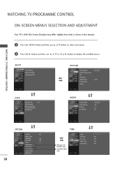
... each menu. 2 Press the G button and then use D or E or F or G button to display the available menus. SETUP Auto Tuning Manual Tuning Programme Edit PICTURE Picture Mode Colour Temperature XD Advanced Aspect Ratio Picture Reset Screen : Dynamic : Auto LOCK Lock System : Off Set Password Block Programme Parental Guidance Input Block AUDIO Sound Mode Auto Volume Balance TV Speaker : Standard : On : 0 : On 38 OPTION Subtitle Input Label SIMPLINK Key Lock Set ID ISM Method Low Power Front Display Factory Reset Model Info : Off : Off : Off : 1 TIME *Plasma TV models only *50...
... each menu. 2 Press the G button and then use D or E or F or G button to display the available menus. SETUP Auto Tuning Manual Tuning Programme Edit PICTURE Picture Mode Colour Temperature XD Advanced Aspect Ratio Picture Reset Screen : Dynamic : Auto LOCK Lock System : Off Set Password Block Programme Parental Guidance Input Block AUDIO Sound Mode Auto Volume Balance TV Speaker : Standard : On : 0 : On 38 OPTION Subtitle Input Label SIMPLINK Key Lock Set ID ISM Method Low Power Front Display Factory Reset Model Info : Off : Off : Off : 1 TIME *Plasma TV models only *50...
Owner's Manual (English)
Page 41
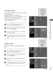
... values. WATCHING TV/PROGRAMME CONTROL MENU EXIT SUBTITLE MARK OK Subtitle Input Label SIMPLINK Key Lock Set ID ISM Method Low Power Front Display Factory Reset Model Info : Off : Off : Off : 1 Subtitle Input label SIMPLINK Key Lock Set ID ISM Method Low Power Front Display Factory Reset Model Info Selection(ON) resets all TV programmes. WARNING: All channel service and user settings will be lost and return to remember this number! To begin Factory Reset, input a 4-digit password in Lock system. G Off...
... values. WATCHING TV/PROGRAMME CONTROL MENU EXIT SUBTITLE MARK OK Subtitle Input Label SIMPLINK Key Lock Set ID ISM Method Low Power Front Display Factory Reset Model Info : Off : Off : Off : 1 Subtitle Input label SIMPLINK Key Lock Set ID ISM Method Low Power Front Display Factory Reset Model Info Selection(ON) resets all TV programmes. WARNING: All channel service and user settings will be lost and return to remember this number! To begin Factory Reset, input a 4-digit password in Lock system. G Off...

Owner's Manual (English)
Page 113
Screen Mute k 05. Volume Mute k 06. Volume Control k 07. Brightness k 09. Colour Temperature k d 0~1 19. Blue Adjustment k g 0 ~ 64 22. Orbiter Time k 0 ~ 64 Setting j 26. If the data is data write mode, it indicates present status data. Back Light m 13. RemoteControl/KeyLock k 15. Send IR Code m m 0~1 28. Input Select x r 0 ~ 64 s 0 ~ 64 t 0 ~ 64 u 0~3 v 0 ~ C8 w 0 ~ C8 $ 0 ~ C8 a See p.114 p 0~3 q 0~1 r 1~ FE s 1~ 3 c See p.114 b See p.114 Plasma TV models only Transmission / Receiving Protocol...
Screen Mute k 05. Volume Mute k 06. Volume Control k 07. Brightness k 09. Colour Temperature k d 0~1 19. Blue Adjustment k g 0 ~ 64 22. Orbiter Time k 0 ~ 64 Setting j 26. If the data is data write mode, it indicates present status data. Back Light m 13. RemoteControl/KeyLock k 15. Send IR Code m m 0~1 28. Input Select x r 0 ~ 64 s 0 ~ 64 t 0 ~ 64 u 0~3 v 0 ~ C8 w 0 ~ C8 $ 0 ~ C8 a See p.114 p 0~3 q 0~1 r 1~ FE s 1~ 3 c See p.114 b See p.114 Plasma TV models only Transmission / Receiving Protocol...


